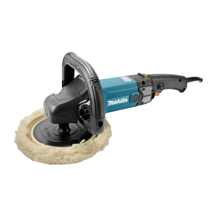
Makita 9237CB - Polisher Manual
- Instruction manual (69 pages) ,
- Technical information (15 pages) ,
- Instruction manual (45 pages)
Advertisement
Explanation of general view
![]()
- Shaft lock
![]()
- Lock button
- Switch trigger
![]()
- Speed adjusting dial
![]()
- Head cover
- Screw
- Screwdriver
![]()
- Protrusion of loop handle
- Matching hole in gear housing
![]()
- Loop handle
- Hex wrench
- Bolt
![]()
- Loop handle
- Hex wrench
- Bolt
![]()
- Wool pad
- Sleeve 18
- Backing pad
- Spindle
- Shaft lock
![]()
- Wool bonnet
- Lock nut
- Rubber pad
- Spindle
- Shaft lock
![]()
- Lock nut wrench
- Shaft lock
![]()
![]()
![]()
![]()
- Screw
- Dust cover
![]()
- Limit mark
![]()
- Screwdriver
- Brush holder cap


SPECIFICATIONS
| Model | 9237CB | |
| Max. capacities | Wool pad | 180 mm |
| Max. capacities | Wool bonnet | 180 mm |
| Spindle thread | M14 or 5/8" (country specific) | |
| Rated speed (n) / No load speed (n0 ) | 3,200 min -1 | |
| Overall length | 431 mm | |
| Net weight | 3.4 kg | |
| Safety class |  /II /II | |
- Due to our continuing program of research and development, the specifications herein are subject to change without notice.
- Specifications may differ from country to country.
- Weight according to EPTA-Procedure 01/2003
Intended use
The tool is intended for polishing.
Power supply
The tool should be connected only to a power supply of the same voltage as indicated on the nameplate, and can only be operated on single-phase AC supply. They are double-insulated and can, therefore, also be used from sockets without earth wire.
Noise
The typical A-weighted noise level determined according to EN60745:
Sound pressure level (LpA): 83 dB (A)
Sound power level (LWA): 94 dB (A)
Uncertainty (K): 3 dB (A)
Wear ear protection
Vibration
The vibration total value (tri-axial vector sum) determined according to EN60745:
Work mode: polishing
Vibration emission (ah, P): 2.5 m/s2 or less
Uncertainty (K): 1.5 m/s2
- The vibration emission during actual use of the power tool can differ from the declared emission value depending on the ways in which the tool is used.
- Be sure to identify safety measures to protect the operator that are based on an estimation of exposure in the actual conditions of use (taking account of all parts of the operating cycle such as the times when the tool is switched off and when it is running idle in addition to the trigger time).
General Power Tool Safety Warnings

Read all safety warnings and all instructions. Failure to follow the warnings and instructions may result in electric shock, fire and/or serious injury.
Save all warnings and instructions for future reference.
POLISHER SAFETY WARNINGS
Safety Warnings Common for Polishing Operation:
- This power tool is intended to function as a polisher. Read all safety warnings, instructions, illustrations and specifications provided with this power tool. Failure to follow all instructions listed below may result in electric shock, fire and/or serious injury.
- Operations such as grinding, sanding, wire brushing or cutting-off are not recommended to be performed with this power tool. Operations for which the power tool was not designed may create a hazard and cause personal injury.
- Do not use accessories which are not specifically designed and recommended by the tool manufacturer. Just because the accessory can be attached to your power tool, it does not assure safe operation.
- The rated speed of the accessory must be at least equal to the maximum speed marked on the power tool. Accessories running faster than their rated speed can break and fly apart.
- The outside diameter and the thickness of your accessory must be within the capacity rating of your power tool. Incorrectly sized accessories cannot be adequately guarded or controlled.
- Threaded mounting of accessories must match the tool spindle thread. For accessories mounted by flanges, the arbour hole of the accessory must fit the locating diameter of the flange. Accessories that do not match the mounting hardware of the power tool will run out of balance, vibrate excessively and may cause loss of control.
- Do not use a damaged accessory. Before each use inspect the accessory such as backing pad for cracks, tear or excess wear. If power tool or accessory is dropped, inspect for damage or install an undamaged accessory. After inspecting and installing an accessory, position yourself and bystanders away from the plane of the rotating accessory and run the power tool at maximum no-load speed for one minute. Damaged accessories will normally break apart during this test time.
- Wear personal protective equipment. Depending on application, use face shield, safety goggles or safety glasses. As appropriate, wear dust mask, hearing protectors, gloves and workshop apron capable of stopping small abrasive or workpiece fragments. The eye protection must be capable of stopping flying debris generated by various operations. The dust mask or respirator must be capable of filtrating particles generated by your operation. Prolonged exposure to high intensity noise may cause hearing loss.
- Keep bystanders a safe distance away from work area. Anyone entering the work area must wear personal protective equipment. Fragments of workpiece or of a broken accessory may fly away and cause injury beyond immediate area of operation.
- Position the cord clear of the spinning accessory. If you lose control, the cord may be cut or snagged and your hand or arm may be pulled into the spinning accessory.
- Never lay the power tool down until the accessory has come to a complete stop. The spinning accessory may grab the surface and pull the power tool out of your control.
- Do not run the power tool while carrying it at your side. Accidental contact with the spinning accessory could snag your clothing, pulling the accessory into your body.
- Regularly clean the power tool's air vents. The motor's fan will draw the dust inside the housing and excessive accumulation of powdered metal may cause electrical hazards.
- Do not operate the power tool near flammable materials. Sparks could ignite these materials.
- Do not use accessories that require liquid coolants. Using water or other liquid coolants may result in electrocution or shock.
Kickback and Related Warnings
Kickback is a sudden reaction to a pinched or snagged rotating wheel, backing pad, brush or any other accessory. Pinching or snagging causes rapid stalling of the rotating accessory which in turn causes the uncontrolled power tool to be forced in the direction opposite of the accessory's rotation at the point of the binding.
Kickback is the result of power tool misuse and/or incorrect operating procedures or conditions and can be avoided by taking proper precautions as given below.- Maintain a firm grip on the power tool and position your body and arm to allow you to resist kickback forces. Always use auxiliary handle, if provided, for maximum control over kickback or torque reaction during start-up. The operator can control torque reactions or kickback forces, if proper precautions are taken.
- Never place your hand near the rotating accessory. Accessory may kickback over your hand.
- Do not position your body in the area where power tool will move if kickback occurs.
Kickback will propel the tool in direction opposite to the wheel's movement at the point of snagging. - Use special care when working corners, sharp edges etc. Avoid bouncing and snagging the accessory. Corners, sharp edges or bouncing have a tendency to snag the rotating accessory and cause loss of control or kickback.
- Do not attach a saw chain woodcarving blade or toothed saw blade. Such blades create frequent kickback and loss of control.
Safety Warnings Specific for Polishing Operations:- Do not allow any loose portion of the polishing bonnet or its attachment strings to spin freely. Tuck away or trim any loose attachment strings. Loose and spinning attachment strings can entangle your fingers or snag on the workpiece.
Additional safety warnings
- Do not allow any loose portion of the polishing bonnet or its attachment strings to spin freely. Tuck away or trim any loose attachment strings. Loose and spinning attachment strings can entangle your fingers or snag on the workpiece.
- Do not leave the tool running. Operate the tool only when hand-held.
- Check that the workpiece supported.
- If working place is extremely hot and humid, or badly polluted by conductive dust, use a short-circuit breaker (30 mA) to assure operator safety.
SAVE THESE INSTRUCTIONS.
DO NOT let comfort or familiarity with product (gained from repeated use) replace strict adherence to safety rules for the subject product. MISUSE or failure to follow the safety rules stated in this instruction manual may cause serious personal injury.
FUNCTIONAL DESCRIPTION

- Always be sure that the tool is switched off and unplugged before adjusting or checking function on the tool.
Shaft lock

Fig.1
- Never actuate the shaft lock when the spindle is moving. The tool may be damaged. Press the shaft lock to prevent spindle rotation when installing or removing accessories.
Switch action

Fig.2
- Before plugging in the tool, always check to see that the switch trigger actuates properly and returns to the "OFF" position when released.
- Switch can be locked in "ON" position for ease of operator comfort during extended use. Apply caution when locking tool in "ON" position and maintain firm grasp on tool.
To start the tool, simply pull the switch trigger. Tool speed is increased by increasing pressure on the switch trigger. Release the switch trigger to stop. For continuous operation, pull the switch trigger and then push in the lock button.
To stop the tool from the locked position, pull the switch trigger fully, then release it.
Speed adjusting dial

Fig.3
The tool speed can be changed by turning the speed adjusting dial to a given number setting from 1 to 6. (At the time when the switch trigger is fully pulled.)
Higher speed is obtained when the dial is turned in the direction of number 6. And lower speed is obtained when it is turned in the direction of number 1.
Refer to the table for the relationship between the number settings on the dial and the approximate tool speed.
| Number | min -1 (RPM) |
| 1 | 600 |
| 2 | 900 |
| 3 | 1,500 |
| 4 | 2,100 |
| 5 | 2,700 |
| 6 | 3,200 |
- If the tool is operated continuously at low speeds for a long time, the motor will get overloaded, resulting in tool malfunction.
- The speed adjusting dial can be turned only as far as 6 and back to 1. Do not force it past 6 or 1, or the speed adjusting function may no longer work.
ASSEMBLY
- Always be sure that the tool is switched off and unplugged before carrying out any work on the tool.
- Always install the loop handle or the side grip.
Removing or installing head cover

Fig.4
To remove the head cover, perform the following steps:
- Remove the screw on the head cover with screwdriver.
- Remove the head cover as shown in the figure. To install the head cover, perform the above steps in reverse.
Installing loop handle
- Always be sure that the loop handle is installed securely before operation.

Fig.5
Always install the loop handle on the tool before operation. Hold the tool's switch handle and the loop handle firmly with both hands during operation. Install the loop handle so that its protrusion will fit into the matching hole in the gear housing.
Install the bolts and tighten them with the hex wrench. The loop handle can be installed in two different directions as shown in the figures whichever is convenient for your work.

Fig.6

Fig.7
For tools which are equipped with a backing pad.
Installing or removing the wool pad (optional accessory)

Fig.8
To install the wool pad, first remove all dirt or foreign matter from the backing pad. Press the shaft lock and screw the backing pad onto the spindle. Insert the sleeve 18 into the center hole of the backing pad. Using the sleeve 18 as a positioning guide, install the wool pad on the backing pad with the sleeve 18 inserted through the center hole of the wool pad. Then remove the sleeve 18 from the backing pad.
To remove the wool pad, just tear it off the backing pad. Then unscrew the backing pad while pressing the shaft lock.
For tools which are equipped with a rubber pad.
Installing or removing the wool bonnet (optional accessory)

Fig.9
Mount the rubber pad onto the spindle. Screw the lock nut onto the spindle.

Fig.10
To tighten the lock nut, press the shaft lock firmly so that the spindle cannot revolve, then use the lock nut wrench and securely tighten clockwise.
To remove the rubber pad, follow the installation procedure in reverse.

Fig.11
Fit the wool bonnet over the rubber pad. Tie a bow knot and tuck the knot and any loose strings between the wool bonnet and the rubber pad.
Installing side grip (handle) (optional accessory)
- Always be sure that the side grip is installed securely before operation.
Screw the side grip securely on the position of the tool as shown in the figure.
![]()
Fig.12

OPERATION
Polishing operation

Fig.13
- Always wear safety glasses or a face shield during operation.
Hold the tool firmly. Turn the tool on and then apply the wool pad/bonnet to the workpiece.
In general, keep the wool pad/bonnet at an angle of about 15 degrees to the workpiece surface.
Apply slight pressure only. Excessive pressure will result in poor performance and premature wear to wool pad/bonnet.
MAINTENANCE
- Always be sure that the tool is switched off and unplugged before attempting to perform inspection or maintenance.
- Never use gasoline, benzine, thinner, alcohol or the like. Discoloration, deformation or cracks may result.
Cleaning the dust cover

Fig.14
Clean the dust cover when necessary as following steps:
- Remove the screw on the dust cover.
- Remove the dust cover.
- Wipe the dust cover to remove dirt.
- Align the hook of the dust cover with groove on the handle.
- Tighten the dust cover with the screw.
If the dust cover is broken or becomes extremely dirty, replace it.
Replacing carbon brushes

Fig.15
Remove and check the carbon brushes regularly. Replace when they wear down to the limit mark. Keep the carbon brushes clean and free to slip in the holders. Both carbon brushes should be replaced at the same time. Use only identical carbon brushes.
Use a screwdriver to remove the brush holder caps. Take out the worn carbon brushes, insert the new ones and secure the brush holder caps.

Fig.16
To maintain product SAFETY and RELIABILITY, repairs, any other maintenance or adjustment should be performed by Makita Authorized Service Centers, always using Makita replacement parts.
OPTIONAL ACCESSORIES
- These accessories or attachments are recommended for use with your Makita tool specified in this manual. The use of any other accessories or attachments might present a risk of injury to persons. Only use accessory or attachment for its stated purpose. If you need any assistance for more details regarding these accessories, ask your local Makita Service Center.
- Lock nut 48
- Lock nut wrench 28
- Sponge pad (Hook & loop)
- Wool pad 180 (Hook & loop)
- Backing pad 165 (Hook & loop)
- Sleeve 18
- Side grip (auxiliary handle)
- Loop handle
- Head cover
NOTE:
- Some items in the list may be included in the tool package as standard accessories. They may differ from country to country.

Documents / ResourcesDownload manual
Here you can download full pdf version of manual, it may contain additional safety instructions, warranty information, FCC rules, etc.
Advertisement
Thank you! Your question has been received!


Need Assistance?
Do you have a question about the 9237CB that isn't answered in the manual? Leave your question here.