Makita 9237CB Technical Information
Hide thumbs
Also See for 9237CB:
- User manual ,
- Instruction manual (69 pages) ,
- Instruction manual (65 pages)
Table of Contents
Advertisement
Quick Links
T
ECHNICAL INFORMATION
Model No.
Description
C
ONCEPT AND MAIN APPLICATIONS
Models 9237C/ 9237CB have been developed based on 9227C/ 9227CB.
In addition to the benefits of the current models, 9237C/ 9237CB feature
the following value-adding benefits:
• Loop handle with elastomer soft grip
• Elastomer bumper on gear housing
• Vent dust cover for protection from ingress of wool fibers
The only specification difference between 9237C and 9237CB is
the method of protection against electric shock:
9237C: Grounding
9237CB: Double insulation
S
pecification
Voltage (V)
110
120
220
230
240
Specification
Diameter of pad: mm (")
No load speed: min.
ˉ
Constant speed control
Soft start
Variable speed control by dial
Protection against electric shock
Power supply cord: m (ft)
Weight according to
EPTA-Procedure 01/2003*
*1 The indication of rpm on Name plate is '3,200 min.
*2 with Loop handle
S
tandard equipment
Loop handle or Side grip .........................................1
Hex wrench 6 . ........................................................1
M8x25 Hex socket head bolt ...................................1 (for some countries)
Sleeve 18 .................................................................1 (for some countries)
Wool pad 180 ..........................................................1 (for some countries)
Wool bonnet 180......................................................1 (for some countries)
Rubber pad 170 ........................................................1 (for some countries)
Sanding lock nut ......................................................1 (for some countries)
Lock nut wrench 28 .................................................1 (for some countries)
Note: The standard equipment for the tool shown above may vary by country.
O
ptional accessories
Grip 36 complete (for 9237C)
Grip 37 (for 9237CB)
Wool pad 180
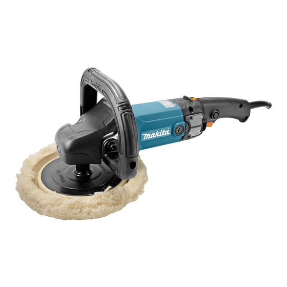
9237C/ 9237CB
Polisher 180mm (7")
Current (A)
Cycle (Hz)
10
50/60
10
50/60
5.7
50/60
5.5
50/60
5.3
50/60
Model No.
¹=rpm
: kg (lbs)
2
Wool bonnet 180
Sanding lock nut
Rubber pad 170
Continuous Rating (W)
Input
1,100
---
1,200
1,200
1,200
9237C
180 (7)
0 - 600/3,200*
Yes
Yes
Yes
(600 - 3,200 min.
Grounding
Europe, Korea: 4.0 (13.1)
Brazil, Chile, Peru, Oceania: 2.0 (6.6)
Other countries: 2.5 (8.2)
3.4 (7.5)
¹'.
ˉ
Lock nut wrench 28
Wrench 17
H
W
Dimensions: mm (")
Length (L)
Width (W)
Height (H)
Max. Output (W)
Output
580
580
710
710
710
9237CB
1
¹)
ˉ
Double insulation
PRODUCT
P 1/ 14
L
431 (17)
198 (7-3/4)
187 (7-3/8)
1,600
1,600
1,800
1,800
1,800
Advertisement
Table of Contents

Related Manuals for Makita 9237CB


Summary of Contents for Makita 9237CB
- Page 1 Polisher 180mm (7") ONCEPT AND MAIN APPLICATIONS Models 9237C/ 9237CB have been developed based on 9227C/ 9227CB. In addition to the benefits of the current models, 9237C/ 9237CB feature the following value-adding benefits: • Loop handle with elastomer soft grip •...
- Page 2 Gear housing when removing Shaft lock pin [2] LUBRICATION Apply Makita Grease SG No. 0 to the portions designated with the black triangle to protect parts and product from unusual abrasion. And apply Isoflex NB52 to the portion designated with the gray triangle.
- Page 3 P 3/ 14 epair [3] DISASSEMBLY/ASSEMBLY [3] -1 Armature DISASSEMBLING Note: Without removing Handle L, Stop ring E-6 on Armature rear side, and Magnet sleeve on Armature rear side, it is impossible to pull out Armature from Motor housing. (1) Separate Gear housing and Armature entirety from Motor housing set as drawn in Fig. 2. Fig.
- Page 4 P 4/ 14 epair [3] DISASSEMBLY/ASSEMBLY [3] -1 Armature (cont.) DISASSEMBLING (2) Remove Armature from Gear housing complete as drawn in Fig. 3. Fig. 3 1. Remove M5x12 Pan head screw from Bearing 2. Pull out Armature section from Gear housing box side of Gear housing complete.
- Page 5 P 5/ 14 epair [3] DISASSEMBLY/ASSEMBLY [3] -1 Armature (cont.) ASSEMBLING (1) Assemble Bearing retainer 48 to Armature assembly as drawn in Fig. 5. Fig. 5 Ball bearing 6201LLB Assemble Bearing retainer 48 to Armature Bearing retainer 48 while facing its collar side to Armature’s fan. Collar Retaining ring S-12 (2) Assemble Armature section to Gear housing complete as drawn in Fig.
- Page 6 P 6/ 14 epair [3] DISASSEMBLY/ASSEMBLY [3] -2 Spiral bevel gear 52, Ball bearing 6201LLB DISASSEMBLING (1) Disassemble Spiral bevel gear 32 and Spindle from Bearing box as drawn in Fig. 7. Fig. 7 1. Separate Bearing box section by unscrewing 2.
- Page 7 P 7/ 14 epair [3] DISASSEMBLY/ASSEMBLY [3] -2 Spiral bevel gear 52, Ball bearing 6201LLB (cont.) ASSEMBLING (1) Assemble Labyrinth ring to Spindle as drawn in Fig. 9. Fig. 9 Put Labyrinth ring into Spindle while facing the collar portion to the reverse side of threaded portion.
- Page 8 P 8/ 14 epair [3] DISASSEMBLY/ASSEMBLY [3]-3 Shaft lock mechanism ASSEMBLING (1) Be sure to use a new Pin cap for replacement and to eliminate all the plastic dust on Shoulder pin 9. (Fig. 12) (2) Assemble the Parts for Shaft lock mechanism as drawn in Fig. 13. Fig.
- Page 9 P 9/ 14 ircuit diagram for 9237C Fig. D-1 Color index of lead wires' sheath Black Blue Transparent Green Orange Yellow White [View from Commutator side] Field Controller Choke coil (if it is used.) Connector 2-SD Green/ yellow lead wire is used for some countries in stead of green.
- Page 10 P 10/ 14 iring diagram for 9237C Fig. D-2 Wiring from Motor housing set Field lead wire (black) and Brush holder’s lead wire (orange) are passed through the right bottom opening of Name plate side. Grounding lead wire (green) has to be routed from the center bottom opening. Grounding lead wire (green) Field lead wire (black) Brush holder’s lead wire (orange)
- Page 11 P 11/ 14 iring diagram for 9237C Fig. D-5 Wiring in Handle set (R) Route Lead wires under Switch Be careful not to put Lead wires as drawn in Fig. 6. on the rib for Terminal block setting. 15 mm Come out at least 15 mm long of Power supply cord from Strain relief, and clamp the cord...
- Page 12 P 12/ 14 ircuit diagram for 9237CB Fig. D-7 Color index of lead wires' sheath Black Blue White Orange Yellow [View from Commutator side] Field Controller Choke coil (if it is used.) Connector 2-SD Polyolefin tube Switch Noise suppressor (if it is used.)
- Page 13 P 13/ 14 iring diagram for 9237CB Fig. D-8 Wiring from Motor housing set Field lead wire (black) and Brush holder’s lead wire (orange) are guided out through the right bottom opening of Name plate side. Field lead wire (black) Brush holder’s lead wire (orange)
- Page 14 P 14/ 14 iring diagram for 9237CB Fig. D-10 Wiring in Handle set (R) Route Lead wires under Switch as drawn in Fig. 11. 15 mm Come out at least 15 mm long of Power supply cord from Strain relief, and clamp the cord with Strain relief.