Table of Contents
Advertisement
Quick Links
Advertisement
Table of Contents

Related Manuals for AEG ACM 9


Summary of Contents for AEG ACM 9
- Page 1 Manual ACM 9 ARE i9 – ARE i9x...
-
Page 2: Table Of Contents
Output data telegram from Industrial Ethernet master ............10 2.2.2 Input data telegram to Industrial Ethernet master ............. 10 2.2.3 2.2.4 ACM 9 – control via RS-232 serial interface ................ 11 ACM 9 error messages ...................... 12 2.2.5 Error messages coming through from ARE i9 ..............13 2.2.6... - Page 3 Version: 10 Manual ACM 9 - ARE i9 release Page: 3 / 51 VER ..........................24 3.3.3 GT ..........................25 3.3.4 TOR ..........................25 3.3.5 NID ..........................26 3.3.6 CID ..........................26 3.3.7 CN ..........................27 3.3.8 RD ..........................27 3.3.9...
- Page 4 Version: 10 Manual ACM 9 - ARE i9 release Page: 4 / 51 General format of instruction set ..................38 3.5.2 VER ..........................38 3.5.3 GT ..........................39 3.5.4 TOR ..........................39 3.5.5 CID ..........................40 3.5.6 CN ..........................40 3.5.7...
-
Page 5: Introduction
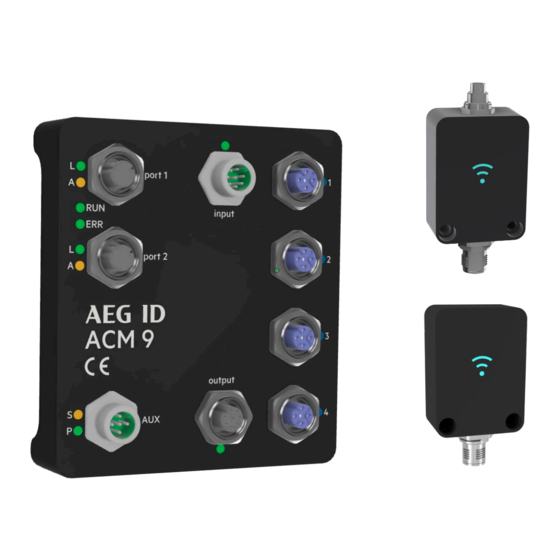
ACM 9 Industrial Ethernet (EtherCAT®, EtherNet/IP™, Profinet®), AEG ID Communication Module, provides Industrial Ethernet connectivity for ARE i9, AEG ID RFID reader family. Both units are dedicated to each other, none of the two is meant to be used without the other. Four ARE i9 units can be hooked up to one ACM 9. -
Page 6: Acm 9
ACM 9 Industrial Ethernet communication module supports Industrial Ethernet connectivity. EtherCAT, EtherNet/IP and Profinet are implemented (only one at a time). ACM 9 has 2 Industrial Ethernet ports, 4 serial ports dedicated to ARE i9 reader family, 4 digital inputs and 4 digital outputs, both linked to their respective reader port. The auxiliary port provides power as well as a serial system interface. -
Page 7: Connectivity
M12 socket 5 Pin male A-coded. PIN 2 – RS-232 GND PIN 3 – RS-232 TX (from ACM 9 point of view) PIN 4 – RS-232 RX (from ACM 9 point of view) PIN 5 – +24V DC / 3A... - Page 8 Version: 10 Manual ACM 9 - ARE i9 release Page: 8 / 51 Industrial Ethernet Port (Port 1, Port 2) M12 socket 4 Pin female D-coded (standard Industrial Ethernet) PIN 1 – TD+ PIN 2 – RD+ PIN 3 – TD- PIN 4 –...
-
Page 9: Grounding
Version: 10 Manual ACM 9 - ARE i9 release Page: 9 / 51 Digital Inputs (input) M12 socket 8-Pin male A-coded PIN 1/2/3/4 PIN 1 – Input for serial port 1 PIN 2 – Input for serial port 2 PIN 3 – Input for serial port 3 PIN 4 –... -
Page 10: Firmware
2.2.3 Input data telegram to Industrial Ethernet master Above output telegram has been sent to ACM 9. ACM 9 sends the command to the appropriate ARE i9, in this case to the ARE i9 hooked up to serial interface port 2. ARE i9 reads the transponder code (UID of transponder) and sends it to ACM 9. -
Page 11: Acm 9 - Control Via Rs-232 Serial Interface
2.2.4 ACM 9 – control via RS-232 serial interface In addition to the Industrial Ethernet control option, ACM 9 can always be controlled directly via a RS-232 interface. The interface is located at the AUX port (see chapter 2.1.3 connectivity for pinout). -
Page 12: Acm 9 Error Messages
Page: 12 / 51 2.2.5 ACM 9 error messages ACM 9 itself has the following error messages. Wrong channel number (Error code #65) A wrong channel number is set to the master output data. Valid channel numbers are from ‘1’ to ‘4’. -
Page 13: Error Messages Coming Through From Are I9
Version: 10 Manual ACM 9 - ARE i9 release Page: 13 / 51 ACM 9 sets master input data to: Hex: … ASCII: <NAK> ‘#’ ‘6’ ‘7’ <CR> Meaning Change Serial Error Text counter interface character port 2.2.6 Error messages coming through from ARE i9 Other error messages can be generated by the reader, if the reader command is wrong. -
Page 14: Are I9 - Family
Version: 10 Manual ACM 9 - ARE i9 release Page: 14 / 51 3. ARE i9 - family ARE i9 is a small industrial RFID reader that is available as a LF - SEMI Industry, LF and HF version. ARE i9 LF hdx - SEMI Industry works with LF hdx transponders. -
Page 15: Connectivity
3.1.3 Connectivity ARE i9 is connected via its M12, 5-Pin male A-coded plug. Power supply as well as communication is provided by ACM 9, communication module. Do not use any other means of powering or communicating to ARE i9 other than an ACM 9 module, otherwise ARE i9 will be damaged. -
Page 16: Transponder Orientation Relative To Are I9
Version: 10 Manual ACM 9 - ARE i9 release Page: 16 / 51 3.1.4 Transponder orientation relative to ARE i9 Disk parallel (recommended) Glass transponder perpendicular (recommended) Direction of travel The highest read range is achieved right above the center of ARE i9 front side. -
Page 17: Read Range For Semi Application
Version: 10 Manual ACM 9 - ARE i9 release Page: 17 / 51 3.1.5 Read range for SEMI application Glass transponder Texas Instruments RI-TRP-DR2B Glass transponder perpendicular (recommended) 120mm 100mm 100mm The highest read range is achieved right above the center of ARE i9 front side. - Page 18 Version: 10 Manual ACM 9 - ARE i9 release Page: 18 / 51 For some applications where space contraints may prevent the use of ARE i9 in its recommended orientation that was decribed above, it is also possible to read a SEMI glass tube transponder in the following way right above the small side of ARE i9.
-
Page 19: Read Range For Miscellaneous Applications
Version: 10 Manual ACM 9 - ARE i9 release Page: 19 / 51 3.1.6 Read range for miscellaneous applications Glass transponder and Disk transponder with different transponder chips (see table at the bottom) Disk transponder parallel (recommended) Glass transponder perpendicular (recommended) The highest read range is achieved right above the center of ARE i9 front side. -
Page 20: Are I9X Hardware
Version: 10 Manual ACM 9 - ARE i9 release Page: 20 / 51 3.2 ARE i9x Hardware ARE i9x is a small industrial RFID reader that is available as a LF - SEMI Industry and LF version. ARE i9x LF hdx - SEMI Industry works with LF hdx transponders. -
Page 21: Protection Class
3.2.3 Connectivity ARE i9x is connected via its M12, 5-Pin male A-coded plug. Power supply as well as communication is provided by ACM 9, communication module. Do not use any other means of powering or communicating to ARE i9x other than an ACM 9 module, otherwise ARE i9x will be damaged. -
Page 22: Transponder Orientation Relative To Aan Xi9F
Version: 10 Manual ACM 9 - ARE i9 release Page: 22 / 51 If it is not possible to ensure such orientation, the Disk transponders can be oriented perpendicular to the front side of ARE i9 and glass tube transponders can be oriented parallel. This will result in some decrease of read range, but in most cases this is acceptable. -
Page 23: Read Range For Semi Applications Using Aan Xi9F
Version: 10 Manual ACM 9 - ARE i9 release Page: 23 / 51 3.2.5 Read Range for SEMI Applications using AAN Xi9F Glass transponder Texas Instruments RI-TRP-DR2B Glass transponder parallel (recommended) 100mm 90mm 90mm 90mm The highest read range is achieved right above the center of AAN Xi9F front side. -
Page 24: Firmware Are I9 Lf Hdx - Semi Industry
Version: 10 Manual ACM 9 - ARE i9 release Page: 24 / 51 3.3 Firmware ARE i9 LF hdx - SEMI Industry ARE i9 LF hdx - SEMI Industry reads low frequency hdx transponders, typically in glass transponder format 4mmx34mm. -
Page 25: Tor
Version: 10 Manual ACM 9 - ARE i9 release Page: 25 / 51 3.3.4 GT GT – Get Tag GT is used to retrieve the transponder UID. Input format: GT<CR> Hex: ASCII: ‘G’ ‘T’ <CR> Output (example): 1234567812345678 <CR> Hex: ASCII: ‘1’... -
Page 26: Nid
Version: 10 Manual ACM 9 - ARE i9 release Page: 26 / 51 3.3.6 NID NID – Double reading of UID to ensure consistency in EMV polluted environment. NID is used to double read a transponder UID to ensure consistency in an EMV polluted environment. The transponder UID... - Page 27 Version: 10 Manual ACM 9 - ARE i9 release Page: 27 / 51 3.3.8 CN CN – Filter no read from being transmitted via interface. CN is used in those cases, where no read information ‘XXXXXXXXXXXXXXXX’ is not to appear on the interface. Only valid transponder UID will be transmitted.
-
Page 28: Vsave
Version: 10 Manual ACM 9 - ARE i9 release Page: 28 / 51 3.3.11 LD LD – lock memory page LD is used to lock a particular memory page from a transponder in the field. Input format: LD<SP> 1<CR> Hex: ASCII: ‘L’... -
Page 29: Error Messages
‘0’ ’2’ <CR> The error code is comprised of a two digit ASCII coded number. Please note that for communication through ACM 9, the appropriate reader number is preceding the error message. The following table displays possible error messages: Error code Meaning "00"... -
Page 30: Firmware Are I9 Lf
Version: 10 Manual ACM 9 - ARE i9 release Page: 30 / 51 3.4 Firmware ARE i9 LF ARE i9 LF works with (all) low frequency transponders in ASK, PSK and FSK modulation. Please see chapter 3.3.13 for details on which transponder chips are implemented. Depending on the selected algorithms, not all instructions below make sense so only those which do work accordingly (e.g. -
Page 31: Tor
Version: 10 Manual ACM 9 - ARE i9 release Page: 31 / 51 3.4.4 GT GT – Get Tag GT is used to retrieve the transponder UID. Input format: GT<CR> Hex: ASCII: ‘G’ ‘T’ <CR> Output (example): 12345678 <CR> Hex: ASCII: ‘1’... -
Page 32: Nid
Version: 10 Manual ACM 9 - ARE i9 release Page: 32 / 51 3.4.6 NID NID – Double reading of UID to ensure consistency in EMV polluted environment. NID is used to double read a transponder UID to ensure consistency in an EMV polluted environment. The transponder UID... - Page 33 Version: 10 Manual ACM 9 - ARE i9 release Page: 33 / 51 3.4.8 CN CN – Filter no read from being transmitted via interface. CN is used in those cases, where no read information ‘XXXXXXXX’ is not to appear on the interface. Only valid transponder UID will be transmitted.
-
Page 34: Vsave
Version: 10 Manual ACM 9 - ARE i9 release Page: 34 / 51 3.4.11 VSAVE VSAVE – Save parameter permanently in ARE i9 flash memory VSAVE is used to save parameters permanently in flash memory of ARE i9 to be available after power on. -
Page 35: Error Messages
‘0’ ’2’ <CR> The error code is comprised of a two digit ASCII coded number. Please note that for communication through ACM 9, the appropriate reader number is preceding the error message. The following table displays possible error messages: Error code Meaning "00"... -
Page 36: Log (Em4305 Chip Specific)
Version: 10 Manual ACM 9 - ARE i9 release Page: 36 / 51 3.4.15 LOG (EM4305 chip specific) EM 4305 EM 4305 is a multi purpose chip from EM microelectronic Marin. It features 512 bit memory and can be configured to transmit in ASK 64-bit Manchester, PSK1, Trovan, ISO 11784/85 fdx-b, pigeon mode among others or work as a simple memory chip. -
Page 37: Ld (Em4305 Chip Specific)
Version: 10 Manual ACM 9 - ARE i9 release Page: 37 / 51 3.4.17 LD (EM4305 chip specific) After the chip is configured correctly, it may be necessary to lock specific memory blocks of EM 4305. Memory blocks from 0 to 13 can be locked. -
Page 38: Firmware Are I9 Hf
Version: 10 Manual ACM 9 - ARE i9 release Page: 38 / 51 3.5 Firmware ARE i9 HF 3.5.1 Instruction Set Communication with ARE i9 is based on a simple ASCII text based protocol. The host sends text based telegrams to ARE i9 and receives text based telegrams back containing the answer to the query. -
Page 39: Tor
Version: 10 Manual ACM 9 - ARE i9 release Page: 39 / 51 3.5.4 GT GT – Get Tag GT is used to retrieve the transponder UID. Input format: GT<CR> Hex: ASCII: ‘G’ ‘T’ <CR> Output (example): 12345678 <CR> Hex: ASCII: ‘1’... -
Page 40: Cid
Version: 10 Manual ACM 9 - ARE i9 release Page: 40 / 51 3.5.6 CID CID – Filter same UID numbers to transmit only once via interface CID is used to filter multiple read transponder UID to transmit only once via interface. There needs to be one different Transponder UID read before the same number will be transmitted again. -
Page 41: Vsave
Version: 10 Manual ACM 9 - ARE i9 release Page: 41 / 51 3.5.8 RD RD – Read transponder memory page RD is used to read an individual memory page from a transponder in the field. Input format: RD<SP> 1<CR>... -
Page 42: Init
‘0’ ’2’ <CR> The error code is comprised of a two digit ASCII coded number. Please note that for communication through ACM 9, the appropriate reader number is preceding the error message. The following table displays possible error messages: Error code Meaning "00"... -
Page 43: Led Instruction Set
Version: 10 Manual ACM 9 - ARE i9 release Page: 43 / 51 3.6 LED instruction set ARE i9 employs a multi-color LED to signal different modes. Basically below colors can be created: The user can choose any color apart from white. This color is reserved for setup help functionality as described below. -
Page 44: Led Standby (Lstb)
Version: 10 Manual ACM 9 - ARE i9 release Page: 44 / 51 Default colors are shown with the instructions. 3.6.1 LED Standby (LSTB) Standby color is Cyan, no flash. Input format: LSTB<SP> 01101<CR> Hex: ASCII: ‘L’ ‘S’ ‘T’ ‘B’... -
Page 45: Led Transponder Number Successfully Read (Lrd)
Version: 10 Manual ACM 9 - ARE i9 release Page: 45 / 51 3.6.3 LED Transponder number successfully read (LRD) Successful read color is green, no flash Input format: LRD<SP> 01001<CR> Hex: ASCII: ‘L’ ‘R’ ‘D’ <SP> ‘0’ ‘1’ ’1’... -
Page 46: Led Error (Lerr)
Version: 10 Manual ACM 9 - ARE i9 release Page: 46 / 51 3.6.6 LED Error (LERR) Error color is red, flashing Input format: LERR<SP> 10011<CR> Hex: ASCII: ‘L’ ‘E’ ‘R’ ‘R’ <SP> ‘1’ ’1’ <CR> Output: 10011<CR> Hex: ASCII: ‘1’... -
Page 47: Led Process Status
3.6.9 LED Setup help (FLED) In order to locate the respective ARE i9 hooked up to a particular port of ACM 9, the instruction FLED is used. This instruction flashes the LED in white for 10 seconds. The color can not be changed. -
Page 48: Led (De)Activate Led Functionality (Led)
Version: 10 Manual ACM 9 - ARE i9 release Page: 48 / 51 3.6.10 LED (De)activate LED functionality (LED) In order to deactivate (or activate) the LED functionality, LED instruction is used. Input format: LED<SP>Parameter<CR> Hex: ASCII: ‘L’ ‘E’ ‘D’... -
Page 49: System Implementation
ACM 9 can be used to achieve this. 4.3 Mounting on metal ACM 9 is typically mounted on a metal DIN hat rail in a metal electrical cabinet. There is no influence of metal on performance of ACM 9 and therefore nothing to watch out for. -
Page 50: Fcc Statement
Page: 50 / 51 5. FCC Statement 5.1 ACM 9 Valid for ACM 9 – EtherCAT, ACM 9 – Profinet, ACM 9 – Ethernet/IP Federal Communications Commissions (FCC) Statement §15.21 You are cautioned that changes or modifications not expressly approved by the part responsible for compliance could void the user’s authority to operate the equipment. - Page 51 AEG Identifikationssysteme GmbH Hörvelsinger Weg 47 89081 Ulm Tel.: +49 731 14 00 88 – 0 Email: sales@aegid.de Web: www.aegid.de...