
Related Manuals for Black & Decker BDXCTSH1

Summary of Contents for Black & Decker BDXCTSH1
- Page 1 BDXCTSH1 Smart Thermostat Installation & Operation Manual Please read before returning this product for any reason.
- Page 2 USING THIS MANUAL BEFORE INSTALLING AND USING THE BDXCTSH1 SMART THERMOSTAT, please read these instructions carefully. This manual is intended as a reference guide for the installation, configuration, and operation of your device. Save all instructions in a safe place for future reference.
-
Page 3: Important Safety Instructions
IMPORTANT SAFETY INSTRUCTIONS WARNING: Read all safety warnings and all instructions. Failure to follow the warnings and instructions may result in electric shock, fire and/or serious injury. WARNING: Never modify this product. Damage or personal injury could result. WARNING: • Follow all applicable electrical codes and regulations regarding the installation or replacement of a thermostat in the local jurisdiction. -
Page 4: Table Of Contents
IN THE BOX ........... . 1 INSTALLING THE BDXCTSH1 SMART THERMOSTAT ... . . 2 DEVICE OVERVIEW . -
Page 5: Customer Assistance & Support
For further information needed on its features, please visit www.ctnovatech.com for frequently asked questions and the electronic manual. ©2021 CT Nova US LLC Mounting Hardware 4700 Duke Drive Suite 200, Mason, OH 45040, USA IN THE BOX Wall Plate (if required) BDXCTSH1 Smart Thermostat with Mounting Plate Installation & Operation Manual... -
Page 6: Installing The Bdxctsh1 Smart Thermostat
INSTALLING THE THERMOSTAT There are 5 steps to install the BDXCTSH1 Smart Thermostat. 1. Determine Wiring Configuration 2. Remove Old Thermostat 3. Install Thermostat Mounting Base 4. Connect Wires 5. Attach Display TOOLS REQUIRED (Not included) The following tools may be required for installation: •... - Page 7 INSTALLING THE THERMOSTAT DETERMINE WIRING CONFIGURATION If the BDXCTSH1 Smart Thermostat is being installed in a new system or if wiring changes are required, refer to APPENDIX A for wiring configurations and skip to “Install Mounting Plate”. When replacing a thermostat and replication of the existing wiring is desired on the BDXCTSH1 Thermostat, the following applies: •...
- Page 8 Wrap wires around a pencil or similar object to prevent them from falling into the wall void. The BDXCTSH1 Thermostat IS NOT COMPATIBLE with supply voltages above 30 VAC. If the old thermostat is connected WARNING: with thick wire and wire nuts or is labeled for voltages higher than 30 VAC, DO NOT INSTALL the Thermostat.
- Page 9 INSTALLING THE THERMOSTAT INSTALL MOUNTING PLATE (with WALL PLATE if required) Note: Use 3/16” drill for wall anchors if no stud is present. Note: See Appendix E for optional junction box mounting. Use the included screws and wall anchors (if required) to attach the Mount- ing Plate to the wall, making sure the wires go through the center opening.
- Page 10 INSTALLING THE THERMOSTAT ATTACH WIRING To insert a wire, flip up the locking lever that corresponds to the labeled wire socket and slide the wire into the socket. Once the wire is inserted, flip the lever down to lock the wire in position. Pull gently on each wire after the locking lever is closed to make sure it is secure.
- Page 11 INSTALLING THE THERMOSTAT ATTACH DISPLAY TO MOUNTING PLATE Slide the display over the Mounting plate and the LCD display will illuminate.
-
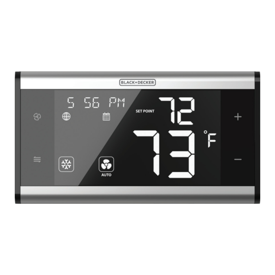
Page 12: Device Overview
DEVICE OVERVIEW BDXCTSH1 SMART THERMOSTAT KEYS DESCRIPTION BUTTON DESCRIPTION Change Increase INCREASE Fan Speed Set Point Change Decrease MODE DECREASE System Mode Set Point... - Page 13 DEVICE OVERVIEW SPECIAL KEY FUNCTIONS KEYS TIME RESULT Briefly press + and - keys to switch between < 3 seconds Programmable and Non-programmable Thermostat. Hold + and – keys for 3 seconds to lock or unlock 3 seconds key pad. Hold the Fan and Mode keys for 3 seconds to en- 3 seconds ter or exit the Parameter Menu.
-
Page 14: Display Elements
DISPLAY ELEMENTS Text display (Menu Item, Time, Date, etc.) Steady = Wi-Fi and Cloud Server connected Cloud Server/ 1 Flash = Wi-Fi connected, No Cloud connection Internet Connection 2 Flashes = No Wi-Fi or Cloud Server connection Thermostat Lock Displayed when thermostat keys are disabled. Indicator Displayed when thermostat schedule Schedule Indicator... - Page 15 Heating/Cooling Modes – Press to change AUTOMATIC CHANGEOVER OFF – The SMARTSTAT – The SMARTSTAT will activate will not activate heating heating or cooling appliance based or cooling* on the room temperature. HEAT – The SMARTSTAT EMERGENCY HEAT – The SMARTSTAT will activate heating displays this with the element to...
-
Page 16: Smart Device Application - Download
SMART DEVICE APPLICATION The BDXCTSH1 Thermostat is designed for remote operation using a smart device application. Before setting up the thermostat, download the BLACK+DECKER HOME application on your IOS or Android device. After download- ing the application, follow the steps in the BLACK+DECKER Home... - Page 17 This page intentionally left blank.
-
Page 18: Thermostat Parameters
THERMOSTAT PARAMETERS To access the BDXCTSH1 Smart Thermostat menu parameters manually, hold down the Mode and Fan buttons for 3 seconds. The following is a list of the available parameters. MENU OPTIONS DESCRIPTION TEXT CON 1H 1-Stage Heating CON 2H... - Page 19 THERMOSTAT PARAMETERS MENU OPTIONS DESCRIPTION TEXT DF 2H1C 2-Stage Heating & 1-Stage Cooling DF 3H2C 3-Stage Heating & 2-Stage Cooling FC2 1H 2-Pipe, 1-Stage Heating FC2 1C 2-Pipe, 1-Stage Cooling HVAC FC2 1H1C 2-Pipe, 1-Stage Heating & 1-Stage Cooling (Cont.) FC2 2H 2-Pipe, 2-Stage Heating FC2 2H1C...
- Page 20 THERMOSTAT PARAMETERS MENU OPTIONS DESCRIPTION TEXT Frost Call for heat will be initiated if temperature drops Protection below 41°F (5°C) NO = Disable, YES = Enable -6F (-3.0C) Calibrate temperature reading by offsetting the dis- Temp play by -6°F to 6°F (-3.0°C to 3.0°C) in 1°F (0.5°C) Calibration 6F (3.0C) increments.
- Page 21 THERMOSTAT PARAMETERS MENU OPTIONS DESCRIPTION TEXT Filter Warning displayed after 700 hours of operation. Warning After replacing the filter select YES, to reset the counter. No power reset will occur Power Reset Pressing Mode will reset power Reset No factory reset will occur Factory Reset Pressing Mode will reset to factory defaults...
-
Page 22: Manual Operation
MANUAL OPERATION MODE CHANGE To change the operating mode, press the Mode ( ) button. The following table shows the mode sequence based on the System Type: Mode Change Sequence System Type Sequence Conventional Heating Heat Pump Dual Fuel (Gas/Electric) Fan Coil... - Page 23 MANUAL OPERATION MODE CHANGE Available Modes Based on HVAC System Setting: System Type Heat Only Conventional Cool Only Heat/Cool Heat Only Cool Only Heat Pump Heat/Cool ...
- Page 24 APPENDIX A – SCHEMATIC WIRING The following are schematic wiring diagrams based on applicable system types. Failure to correctly wire the BDXCTSH1 Thermostat could WARNING: result in death or serious injury. The local jurisdiction may require installation by authorized service personnel.
- Page 25 APPENDIX A – SCHEMATIC WIRING Failure to correctly wire the BDXCTSH1 Thermostat could WARNING: result in death or serious injury. The local jurisdiction may require installation by authorized service personnel. Conventional Boiler / AC (Non-Heat Pump) – 2 Transformers...
- Page 26 APPENDIX A – SCHEMATIC WIRING Failure to correctly wire the BDXCTSH1 Thermostat could WARNING: result in death or serious injury. The local jurisdiction may require installation by authorized service personnel. Heat Pump – 1 Transformer...
- Page 27 APPENDIX A – SCHEMATIC WIRING Failure to correctly wire the BDXCTSH1 Thermostat could WARNING: result in death or serious injury. The local jurisdiction may require installation by authorized service personnel. Fan Coil Unit – 4-Pipe – 1 Transformer...
- Page 28 APPENDIX A – SCHEMATIC WIRING Failure to correctly wire the BDXCTSH1 Thermostat could WARNING: result in death or serious injury. The local jurisdiction may require installation by authorized service personnel. Fan Coil Unit – 2-Pipe – 1 Transformer...
- Page 29 This page intentionally left blank.
-
Page 30: Appendix B - Warranty
APPENDIX B - WARRANTY Three-Year Limited Warranty CT Nova warrants to the original consumer purchaser only that this product and the component parts thereof, will be free from defects in workmanship and materials. CT Nova will, repair or replace, at its sole option and discretion, this product or any defective parts. CT Nova’s liability hereunder shall be limited to repair or replacement of the defective part or parts, and such cor- rection shall constitute a fulfillment of all of CT Nova’s warranties hereunder. - Page 31 APPENDIX B - WARRANTY LIMITATION OF REMEDIES AND DAMAGES. REPAIR OR REPLACEMENT AS PROVIDED UN- DER THIS WARRANTY IS THE EXCLUSIVE REMEDY OF THE CONSUMER. CT NOVA SHALL NOT BE LIABLE FOR ANY INCIDENTAL OR CONSEQUENTIAL DAMAGES, INCLUDING BUT NOT LIMITED TO ATTORNEYS’ FEES AND/OR COSTS OF LITIGATION, FOR BREACH OF ANY EXPRESS OR IMPLIED WARRANTY ON THIS PRODUCT.
- Page 32 APPENDIX C - COMPLIANCE This device complies with Part 15 of the FCC Rules. Operation is subject to the following two conditions: (1) This device may not cause harmful interference, and (2) This device must accept any interference received, including interference that may cause undesired operation.
-
Page 33: Appendix C - Compliance: Fcc/Industry Canada
APPENDIX C - COMPLIANCE FCC AND INDUSTRY CANADA RF Radiation Exposure statement: This equipment complies with FCC and Industry Canada RF radiation exposure limits set forth for an uncontrolled environment. This equip- ment should be installed and operated with a minimum distance of 20 centimeters between the antenna and all persons. -
Page 34: Appendix D - Thermostat Specifications
APPENDIX D - SPECIFICATIONS Model BDXCTSH1 Smart Thermostat Temperature Units °F or °C Operating Temperature 32°F to 122°F (0°C to 50°C) Storage Temperature 14°F to 140°F (-10°C to 60°C) Humidity Range < 90% RH Non-condensing Power Input 18-30 VAC, 60 Hz... -
Page 35: Appendix E - Alternate Junction Box Installlation
1/4-Turn Fasteners Mounting Plate To install the BDXCTSH1 Thermostat on a junction box, remove the Wall Plate Insert from the Wall plate. Attach the Wall Plate Insert to the junction box using appropri- ate cover plate screws. Snap the Wall Plate to the Insert and use the plastic -turn... -
Page 36: Trademark Acknowledgement
WARNING: This product can expose you to chemicals including Styrene, which is known by the State of California to cause cancer. For more information go to www.P65Warnings.ca.gov BDXCTSH1 IN STA L LATIO N & OPERATION MANUAL BDXC TSH1 -E N B+D-GM-BDXCTSH1-EN-202106 v1...