Advertisement
Quick Links
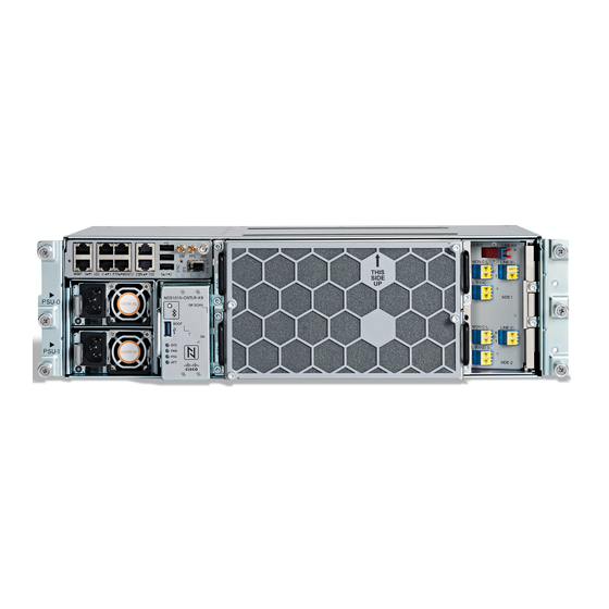
Install Cisco NCS 1010 Modules
This chapter describes the tasks to install Cisco NCS 1010 modules.
Caution
•
•
•
•
•
•
Install PSU
Use this task to install PSU into the Cisco NCS 1010 chassis. You can install two AC PSUs or two DC PSUs
in a chassis.
Procedure
Step 1
Orient the PSU correctly before inserting.
Always populate the modular slots in the Cisco NCS 1010 chassis with respective modules (line card, controller,
PSU, and fan trays). Perform the replacement or upgrade of the modules (Online Insertion or Removal ( OIR))
only when the ambient temperature is below 30 degree Celsius. Complete the OIR of modules within five
minutes to prevent overheating of the components.
Install PSU, on page 1
Install Controller, on page 6
Install Line Card, on page 7
Install Fan Tray, on page 9
Install Fan Filter, on page 11
Install Protection Cover, on page 12
Install Cisco NCS 1010 Modules
1
Advertisement

Related Manuals for Cisco NCS 1010


Summary of Contents for Cisco NCS 1010
- Page 1 Install Fan Filter, on page 11 • Install Protection Cover, on page 12 Install PSU Use this task to install PSU into the Cisco NCS 1010 chassis. You can install two AC PSUs or two DC PSUs in a chassis. Procedure Step 1 Orient the PSU correctly before inserting.
- Page 2 Connect AC Power to Cisco NCS 1010 Caution Cisco NCS 1010 relies on the protective devices in the building installation to protect against short circuit, overcurrent, and ground faults. Ensure that the protective devices comply with local and national electrical codes.
- Page 3 Install Cisco NCS 1010 Modules Connect AC Power to Cisco NCS 1010 Figure 2: Rating Label for AC Power AC power ratings: The voltage rating value for AC power ranges either 200–240 or 100–127 V depending on the standards in various countries.
- Page 4 Connect DC Power to Cisco NCS 1010 Caution Cisco NCS 1010 relies on the protective devices in the building installation to protect against short circuit, overcurrent, and ground faults. Ensure that the protective devices comply with local and National Electrical Codes.
- Page 5 Verify that the correct fuse panel is installed in the top mounting space. Step 2 Measure and cut the cables as required to reach Cisco NCS 1010 from the fuse panel. Step 3 Connect the office battery and return cables according to the fuse panel engineering specifications.
-
Page 6: Install Controller
Install Controller Figure 5: Connecting DC Power DC power cable Install Controller Use this task to install controller into the Cisco NCS 1010 chassis. Procedure Step 1 Orient the controller appropriately before inserting. Check for the This Side Up label. - Page 7 Step 3 Using a screwdriver, tighten the two captive screws to a torque value of 0.65 N-m (5.75 lbs-in). Install Line Card Use this task to install the line card into the Cisco NCS 1010 chassis. Procedure Step 1 Orient the line card.
- Page 8 Install Cisco NCS 1010 Modules Install Line Card Figure 7: Cisco NCS 1010 Chassis Backplane connector Slide Guides Figure 8: Inserting the Line Card Grooves Handle Captive Screws (Two captive screws on each side of the line card) Step 3 Insert the line card into the chassis.
- Page 9 Install Cisco NCS 1010 Modules Install Fan Tray Step 4 Tighten the captive screws available in the left and right side handles of the line card, using a screw driver with a torque value of 1.5 N-m (13.3 lbs-in). Install Fan Tray Use this task to install the fan trays into the chassis.
- Page 10 Install Cisco NCS 1010 Modules Install Fan Tray Figure 10: Rear View of the Fan Tray Guide pin Step 2 Holding the handles with both hands, insert the fan tray into the slot on the front side of the chassis.
- Page 11 Step 4 Repeat the preceding steps to insert and fix the second fan tray. Install Fan Filter Use this task to assemble the fan filter on the Cisco NCS 1010 chassis. Procedure Step 1 Align the four captive screws in the fan filter with the respective standoffs in the fan trays. Check for the This Side Up label.
- Page 12 Install Cisco NCS 1010 Modules Install Protection Cover Install Protection Cover Use this task to install the transparent plastic protection cover to enclose the faceplate of the line card, after the fibers are connected on the faceplate of the line card.
- Page 13 Install Cisco NCS 1010 Modules Install Protection Cover Figure 14: Protection cover Standoffs Captive screws Step 3 Tighten the captive screws available in the protection cover, such that the screws get fixed into the standoffs. Remove the protection cover to access the line card faceplate and reinstall after the fibers are connected.
- Page 14 Install Cisco NCS 1010 Modules Install Protection Cover Install Cisco NCS 1010 Modules...