Cisco LightStream 1010 Configuration Note
Atm switch processor module
Hide thumbs
Also See for LightStream 1010:
- Getting started manual (182 pages) ,
- Hardware installation manual (40 pages) ,
- Configuration note (19 pages)
Table of Contents
Advertisement
Quick Links
Doc. No.
78-2988-01 Rev. A0
LightStream 1010 ATM Switch Processor Module
Configuration Note
Product Numbers: WATM-ASP1=
This document contains instructions for installing and configuring the LightStream 1010 ATM
switch processor (ASP) module. For a complete description of commands used to configure and
maintain the ASP, refer to the LightStream 1010 ATM Switch Software Configuration Guide and
LightStream 1010 ATM Switch Command Reference publications. For complete hardware
configuration and maintenance procedures, refer to the LightStream 1010 ATM Switch User Guide
publication.
Cisco documentation and additional literature are available on a CD called Cisco Connection
Documentation, Enterprise Series. The CD is updated and shipped monthly, so it might be more
up-to-date than the printed documentation. To order the Cisco Connection Documentation,
Enterprise Series CD, contact your local sales representative or call Customer Service. The CD is
available both as a single CD and as an annual subscription. You can access Cisco technical
documentation on the World Wide Web Universal Resources Locator (URL)
http://www.cisco.com.
Sections in this document include the following:
•
•
•
•
•
•
•
•
Warning
switch, chassis, power supplies, fan assembly, or modules.
Copyright © 1996
Cisco Systems, Inc.
All rights reserved.
What is the LightStream 1010 ATM Switch?
ASP Description
ASP LEDs
Preparing Network Connections
Safety Recommendations
Installing and Replacing the ASP
Configuring the Interfaces
ASP Configuration Defaults
Only trained and qualified personnel should install or replace the LightStream 1010 ATM
1
Advertisement
Table of Contents

Related Manuals for Cisco LightStream 1010


Summary of Contents for Cisco LightStream 1010
- Page 1 Enterprise Series CD, contact your local sales representative or call Customer Service. The CD is available both as a single CD and as an annual subscription. You can access Cisco technical documentation on the World Wide Web Universal Resources Locator (URL) http://www.cisco.com.
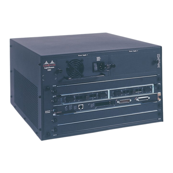
- Page 2 The LightStream 1010 uses a five-slot, modular chassis featuring the option of dual, fault-tolerant, load-sharing power supplies (See Figure 1.) The central slot in the LightStream 1010 is dedicated to a single, field-replaceable ATM switch processor (ASP) module that supports both the 5-Gbps shared memory and the fully nonblocking switch fabric.
- Page 3 LightStream 1010 Workgroup Configuration Example Workstations LightStream 1010 ATM Switch Servers Figure 3 shows an example of a network configuration using the LightStream 1010 ATM switch for a campus backbone. Figure 3 LightStream 1010 Backbone Configuration Example Catalyst 5000 Catalyst 5000...
- Page 4 Access to the reset switch, located behind the faceplate of the ASP, is through a small hole approximately 1.5 inches to the right of the ASP status LED. (See Figure 5.) 4 LightStream 1010 ATM Switch Processor Module Configuration Note...
- Page 5 The dual-height Personal Computer Memory Card International Association (PCMCIA), Type II, card slot (shown in Figure 5) can be used to store Cisco Internetwork Operating System (IOS) software or system configuration information on a Flash card. The switch may also boot from the software stored on the Flash card.
- Page 6 Per-virtual channel (VC) statistics collection • Multicast cell replication • Congestion control for the available bit rate (ABR) service • Policing • Threshold based Selective Discard • Intelligent Early Packet Discard 6 LightStream 1010 ATM Switch Processor Module Configuration Note...
-
Page 7: Specifications
ASP Description Supporting such capabilities on the field-replaceable feature card allows you to upgrade the LightStream 1010 in the field as and when such standards evolve and more advanced mechanisms are required. Note When you upgrade the feature card you must power down the switch and remove the ASP module. - Page 8 Off—No signal detected. On—Shows activity accessing the PCMCIA slot. 1. This LED is located to the right of the Ethernet cable connector. Refer to the LightStream 1010 ATM Switch User Guide for more information. 2. This LED is located to the right of the Ethernet cable connector. Refer to the LightStream 1010 ATM Switch User Guide for more information.
- Page 9 If you intend to build your own cables, refer to the cable pinouts in the section “Installing the LightStream 1010 Switch” in the LightStream 1010 ATM Switch User Guide publication. For ordering information, contact a customer service representative.
- Page 10 You need an Ethernet cable with RJ-45 male connectors (see Figure 8) between the Ethernet port and the Ethernet network. See the ASP Ethernet RJ-45 connector information in the section “Enet Port” in the chapter “LightStream 1010 ATM Switch Hardware” in the LightStream 1010 ATM Switch User Guide.
-
Page 11: Safety Recommendations
Do not work on the system or connect or disconnect cables during periods of lightning Warning activity. • Never install telephone jacks in wet locations unless the jack is specifically designed for wet locations. LightStream 1010 ATM Switch Processor Module Configuration Note... -
Page 12: Preventing Electrostatic Discharge Damage
When removing any module, connect the equipment end of the strap to one of the captive installation screws on an installed PAM or power supply. (See Figure 10.) Figure 10 Placement of Electrostatic Discharge Wrist Strap 12 LightStream 1010 ATM Switch Processor Module Configuration Note... - Page 13 Any ASP that is only partially connected to the backplane can hang the bus. For more information, see the section “Installing and Replacing the ASP.” Figure 11 shows the ejector levers, which you must use when inserting or removing the ASP or CAMs. LightStream 1010 ATM Switch Processor Module Configuration Note...
-
Page 14: Tools Required
Place the removed ASP on an antistatic mat or antistatic foam. Installing ASP Slot number 2 contains the ASP, Figure 12, from top to bottom when viewing the chassis from the front. 14 LightStream 1010 ATM Switch Processor Module Configuration Note... - Page 15 Avoid touching the card. (See Figure 13.) Step 3 Place the back of the ASP in the slot and align the notch on the sides of the module carrier with the groove in the slot. LightStream 1010 ATM Switch Processor Module Configuration Note...
-
Page 16: Configuring The Interfaces
After you install the module, use the following information to configure the module and the individual interfaces on the ASP module. In the LightStream 1010 ATM Switch User Guide the section “LightStream 1010 ATM Switch Hardware” contains an overview of the port and module numbering scheme used to configure the ASP. -
Page 17: Port Addresses
Port IDs In the LightStream 1010 switch, port IDs specify the actual physical location of each PAM port on the front of the switch. (See Figure 14.) The address is composed of a three-part number in the format card/subcard/port number. The first number identifies the slot in which the module is installed. - Page 18 To display information about a specific interface, use the show interface command with the interface type and port address in the format show interface atm card/subcard/port. This command is described in the LightStream 1010 ATM Switch Command Reference publication.
-
Page 19: Cisco Connection Online
This document is to be used in conjunction with the LightStream 1010 ATM Switch User Guide and the LightStream 1010 ATM Switch Command Reference publication. AtmDirector, Catalyst, CD-PAC, CiscoAdvantage, CiscoFusion, Cisco IOS, the Cisco IOS logo, CiscoLink, CiscoPro, the CiscoPro logo, CiscoRemote, the CiscoRemote logo, CiscoSecure,... - Page 20 Cisco Connection Online 20 LightStream 1010 ATM Switch Processor Module Configuration Note...