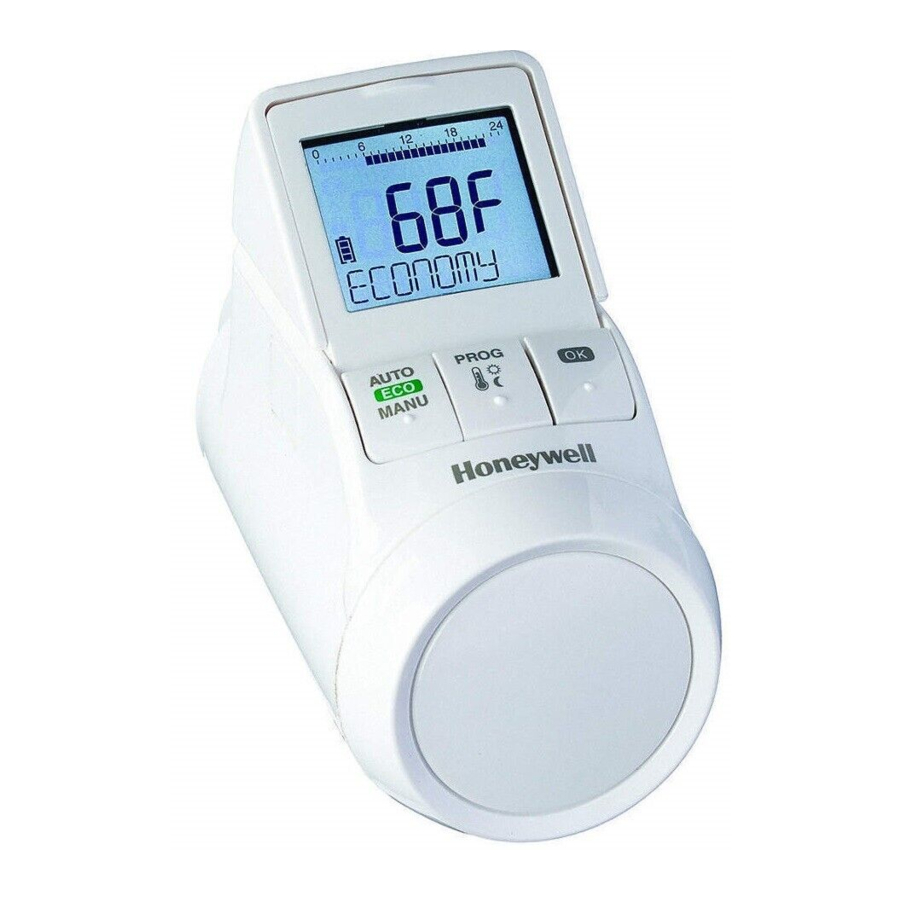
Honeywell TheraPro HR90 - Electronic Radiator Controller Manual
- Quick start manual (12 pages) ,
- Instruction manual (17 pages) ,
- Owner's manual (40 pages)
Advertisement
- 1 Scope of delivery
- 2 Brief description
- 3 Device overview
- 4 Installation
- 5 Operation
- 6 Programming – Operating modes
- 7 Programming – Temperatures
- 8 Programming – Time program
- 9 Controller operating parameters
- 10 Further functions
- 11 Help with problems
- 12 Technical data
- 13 Disposal
- 14 Programming – Overview
- 15 Documents / Resources
Scope of delivery
The radiator controller packaging contains:

- Radiator controller with valve baseplate M30 x 1.5; batteries included
- Display support
- Valve adapter type Danfoss RA
- Screws for securing radiator controller and battery compartment

Danger of suffocation!
![]() Keep packaging materials away from children.
Keep packaging materials away from children.
Brief description
With the electronic radiator controller, you can set your room temperature exactly to your requirements while additionally saving energy.
Please note: The HR90 radiator controller does not directly switch your boiler on/off. It provides local room temperature control whilst the boiler is running. The boiler will be switched on/off by other controls such as timer, thermostat, etc.
User-friendly
- Large, adjustable display with backlight.
- Convenient programming by removing the radiator controller from the valve.
- Copy function for transferring the time program to other HR90 radiator controllers.
Installation
- The radiator controller fits on the most common radiator valves of the type M30 x 1.5.
- After mounting the radiator controller operates immediately to the factory set program.
Features for your convenience
- Individual programs for each day of the week.
- Up to 6 setpoints per day and 3 different temperatures.
- Holiday, party and special day operating modes can be set easily.
- Parameters can be set individually, see Section 9.
- Operation lock/child-proofing to protect against unauthorized operation.
- Optional connection to external sensors and window position contact
Energy saving features
- With the window function, the radiator valve is closed when ventilating the room.
- In ECO mode, the room temperature is lowered by 3°C.
- Optimized control of the room temperature.

Care of use is required!
 Use the radiator controller only in accordance with these operating instructions.
Do not let children play with the radiator controller.
Device overview
Operating elements and display

- Heating period/setback period in hours
- Day of the week 1... 7 (Monday... Sunday). Displayed only while the time program is being programmed
- Temperature display: e.g. set point temperature (factory setting) or measured temperature, if configured in Parameter 9
- Text display with 9 characters
- Button
![]() : Confirm settings
: Confirm settings - Button PROG: Select the operating modes, set the time program; Press button >10 seconds): access to the parameter menu; Programming: Back to next level up
- Adjustment dial: Change the set point, navigate menu
- Button AUTO/ECO/MANU: Change between automatic, ECO and manual mode In programming mode: Exit (without storing)
- Battery status
- Operation lock
- Symbol for Comfort temperature 1
![]() , Comfort temperature 2
, Comfort temperature 2 ![]() , Setback temperature
, Setback temperature ![]()

Battery display
| Battery status | Meaning |
 | Batteries fully charged |
 | Batteries half charged |
 | Batteries have to be replaced soon |
 | Flashing display: Batteries are dead and have to be replaced |
Installation
Ready to operate in three steps:
- Insert batteries
- Set the language, time and date
- Mount on radiator – FINISHED
Inserting/changing batteries
The radiator controller is set for the following battery type:
- 2 alkaline cells 1.5 V; type LR6, AA, AM3 You can instead use the following batteries or accumulator cells:
- Lithium 1.5 V; type LR6, AA, AM3
- NiMH 1.2 V; type LR6, AA, AM3

- If lithium or NiMH batteries are used, Parameter 14 has to be adapted.
- Always change batteries in pairs.
- Pull off the adjustment dial. To do so, start at the notch on the bottom of the device.
![]()
- If used, unscrew any fastening screws from the battery compartment.
![]()
- Release the lock and fold out battery spring. The battery compartment is now accessible.
![]()
- Insert the batteries. Ensure that the polarity "+" and "–" is correct.
![]()
- Fold down the battery spring and latch it in.
![]()
- Option: Screw the battery spring to secure the batteries against removal.
![]()
- Place the adjustment dial back on. First the software version number and then the language deutsch (German) is displayed.
- If desired, use the adjustment dial to select a different language.
- Confirm the selected language with the
![]() button. hour is displayed.
button. hour is displayed.


The language selection is only displayed during initial commissioning. During future battery changes, setting of time and date is prompted directly.
The battery life of new alkaline cells amounts to approx. 2 years. The batteries need changing when the symbol  flashes. All settings are retained when the batteries are changed.
Explosion hazard!
Never charge non rechargeable batteries.
Never short-circuit batteries or throw them into fire.
Dispose of used batteries ecologically.
Setting the time and date
- When
![]() is displayed, use the adjustment dial to set the current hour and confirm with
is displayed, use the adjustment dial to set the current hour and confirm with ![]() .
. ![]() is displayed.
is displayed. - Use the adjustment dial to set the current minute and confirm with
![]() .
. ![]() is displayed.
is displayed. - Use the adjustment dial to set the current year and confirm with
![]() .
. ![]() is displayed.
is displayed. - Use the adjustment dial to set the current month and confirm with
![]() .
. ![]() is displayed.
is displayed.
 is displayed, use the adjustment dial to set the current hour and confirm with
  is displayed.
 is displayed.
 is displayed.
 is displayed.
- Use the adjustment dial to set the current day and confirm with
![]() .
.
The normal display with set temperature and selected operating mode is displayed.
Checking/changing the time and date
Proceed as follows to check or to change the date and time later on:
- Press the PROG button.
- Select time date and confirm with
![]() .
. ![]() is displayed.
is displayed. - Further checking/changing is carried out as described above.

Mounting the radiator controller
The radiator controller can be mounted on all common thermostatic valves with an M30 x 1.5 connection without draining system.
Prevent damage to the radiator controller through humidity and moisture!
Mount the radiator controller in dry, closed rooms only.
Protect the radiator controller against humidity, moisture, dust, direct sunlight or exposure to excessive heat.
Removing the old thermostat head

- Turn the old thermostat head counter-clockwise until it stops and loosen the mounting ring.
- Remove the old thermostat head from the radiator valve.
Selecting the adapter
The radiator controller fits on common radiator valves of the type M30 x 1.5. Adapters are required for some valve types.
- Check whether an adapter is required and, if necessary, select the appropriate adapter.
| Brand | Illustration | Adapter |
| HoneywellBraukmann, MNG, Heimeier, Oventrop valves M30 x 1.5 |  | Not required |
| Danfoss RA |  | Supplied |
| Danfoss RAV |  | |
| Danfoss RAVL |  |
- Slide the adapter onto the radiator valve and turn it until you feel it click into place.
- If necessary, screw the adapter tight with a screw.
Mounting the valve baseplate


- Separate the valve baseplate from the radiator controller. To do so, push the slide towards
![]() .
.
 .
.- Turn the adjustment dial of the valve baseplate counter-clockwise until it stops.
- Put the valve baseplate onto the radiator valve or the adapter and tighten by hand (without tools!).
Mounting the radiator controller

- Ensure that the slide on the radiator controller is in the open position.
- Put the radiator controller onto the valve baseplate so that the indentation latches in and is no longer visible.
- Lock the radiator controller in the end position. To do so, push the slide towards
![]() .
.
After approx. 1 minute![]() (self-test) is displayed. Afterwards the radiator controller changes to automatic mode.
(self-test) is displayed. Afterwards the radiator controller changes to automatic mode.
![]()
 (self-test) is displayed. Afterwards the radiator controller changes to automatic mode.
The radiator controller only operates if it is locked correctly in the end position.
FINISHED! – After mounting, the radiator controller operates immediately in the factory setting (standard time program).
Securing the radiator controller
The radiator controller and the batteries can be secured against removal by using the supplied screws.

Setting the position of the display
In order to improve the legibility the display of the radiator controller can be tilted to different positions (10°, 20°, 30°, 40°).
The angle of 40° can be fixed with the supplied display support.
Mounting

- Lift the display and set it to the desired angle.
- If desired, tilt the display by 40° and slide the display support from above between the display and the housing until it latches in.
Unmounting

Press the display support in at the back and remove it upwards.
Connecting optional sensors and window contact
The following external sensors and window contacts can be connected to the HR90 radiator controller:
- HCW23 setpoint adjuster
- RF20 room sensor
- HCA30 floating window contact
The ACS90 cable is required to connect external sensors and the window contact.
- Micro B mini-plug / open ends
- 2 m long
- Not included in the scope of delivery
Operation with HCW23 setpoint adjuster
The room temperature is measured by the HCW23 setpoint adjuster. The HR90 internal room temperature sensor is not used in this particular application. The adjustment dial of the HCW23 can be used to change the room temperature ±12 K as an offset to the temperature set/programmed at the HR90. The offset setting remains valid until it is changed again.
Operation with RF20 room sensor
The room temperature is measured by the external RF20 room sensor. The HR90 internal room temperature sensor is not used in this particular application.
Operation with window contact
When the window is opened, the window contact is opened and the radiator valve closes. When the window is closed again, the radiator controller returns to normal operation.
The frost-protection function ensures that the radiator valve opens when the temperature drops below 5°C.
- When de-installing a connected room sensor RF20 or room unit HCW23, remove the batteries and insert them again to avoid error messages.
- When de-installing the window contact, change parameter 17 to 1 or 0, see section 9.
Cable connection
For further information also refer to the documentation for HCW23, RF20 and HCA30.
Connect the ACS90 cable as follows to the external sensor and window contact:
HCW23 setpoint adjuster

RF20 room sensor

RF20 room sensor and floating HCA30 window contact

HCA30 floating window contact

Connecting the cable with the HR90 radiator controller

- Remove the side cover from the radiator controller.
- Insert the cable ASC90 into the HR90 radiator controller.
The radiator controller recognizes the connected sensor / window contact automatically.
Operation
Standard time program (factory setting)
In automatic mode, the radiator controller automatically controls the room temperature in accordance with the stored time program.
Week program 1: At home all day
Factory preset time program is set for each day of the week Mo – Su (1 – 7):

| Setpoint | Time | Temperature |
| 1 | 6:00 – 22:00 |  20°C (Comfort temperature 1) 20°C (Comfort temperature 1) |
| 2 | 22:00 – 6:00 |  16°C (Setback temperature) 16°C (Setback temperature) |
- Two further week programs are stored in the radiator controller.
- You can also adapt one of the stored week programs to your individual requirements.
Adapting the temperature temporarily
If you want to change the temperature specified by the time program temporarily:
Set your desired temperature using the adjustment dial.
The change remains in effect until the next setpoint.
The process of changing the temperatures permanently is described in Section 7.
Saving energy in ECO mode
In ECO mode, the room temperature in automatic mode specified by the time program is lowered by 3°C.
To activate ECO mode, press the button AUTO/ ECO/MANU until  is displayed.
The displayed temperature is reduced by 3°C.
ECO mode runs until you press the button AUTO/ECO/MANU again and select a different operating mode.
Manual mode
In manual mode, the radiator controller operates at the (manually) set temperature until you change the temperature or change to a different operating mode.
To activate the manual mode. press the button AUTO/ECO/MANU until  is displayed.
The temperature can be adjusted manually using the adjustment dial.
Manual mode runs until you press the button AUTO/ ECO/MANU again and select a different operating mode.
Programming – Operating modes
Overview of the operating modes
- "Party" operating mode: In this operating mode, you can specify a temperature for a number of hours. After the set period has expired, the radiator controller changes back to automatic mode.
- "Day off" operating mode: If, for example, a public holiday during the week, the automatic mode settings may not meet your requirements on these days. In such cases you can activate a different time program for one or more days. After the set period has expired, the radiator controller changes back to automatic mode.
- "Holiday" operating mode: In this operating mode you can specify a temperature for a specific number of days. After the set period has expired, the radiator controller changes back to automatic mode.
Selecting operating modes
Selecting the "Party" or "Holiday" operating mode
- Press the PROG button and turn the adjustment dial to the left until
![]() or
or ![]() is displayed.
is displayed. - Confirm the selected operating mode with the
![]() button. Hours or Days flashes.
button. Hours or Days flashes. - Use the adjustment dial to set the desired number of hours or days and confirm with
![]() . The temperature display flashes.
. The temperature display flashes. - Use the adjustment dial to set the desired temperature and confirm with
![]() .
.
The selected operating mode and the set temperature are displayed.
 or
or  is displayed.
Selecting the "Day off" operating mode
- Press the PROG button and turn the adjustment dial to the left until
![]() is displayed.
is displayed. - Confirm the selected operating mode with the
![]() button.
button. ![]() flashes.
flashes. - Use the adjustment dial to set the desired number of days and confirm with
![]() .
.
The selected operating mode is displayed.
 is displayed.
 flashes.
- The procedure of creating the time program for special days is described in Section 8.
- When you enter the number of days for holidays/ special day the current day counts as the first day.
- An overview of the program structure is shown on the last page of these instructions.
Programming – Temperatures
Three preset temperatures can be assigned to the set points in the time program:
- Comfort temperature 1
![]() Factory setting 20°C
Factory setting 20°C - Comfort temperature 2
![]() Factory setting 22°C
Factory setting 22°C - Setback temperature
![]() Factory setting 16°C
Factory setting 16°C
Setting the temperatures
- Press the PROG button.
![]() 1 is displayed.
1 is displayed. - Press the
![]() button, use the adjustment dial to set the Comfort temperature 1 and confirm with
button, use the adjustment dial to set the Comfort temperature 1 and confirm with ![]() .
. ![]() is displayed briefly and then again
is displayed briefly and then again ![]()
- Turn the adjustment dial clockwise until the next temperature is displayed.
- Repeat Steps 2 and 3 for the Comfort temperature 2 and the Setback temperature.
- Use the AUTO button to exit programming.
 1 is displayed.
 is displayed briefly and then again
The three preset temperatures (Comfort temperature 1, 2 and Setback temperature) can be changed at any time.
- During programming the PROG button can be used to return to the next level up.
- You can abort programming at any time by using the AUTO button.
An overview of the program structure is shown on the last page of these instructions.
Operating hints
Operating the radiator controller comfortably
The radiator controller can be removed from the radiator to facilitate programming.

- Unlock the radiator controller. To do so, push the slide at the radiator controller towards
![]() .
. - Pull the radiator controller off the valve baseplate.
Lost your way in the program?
Press the button AUTO/ECO/MANU  is displayed. The last entry is rejected.
Programming – Time program
Planning the time program
You can specify up to 6 setpoints per day.
The following has to be assigned to each setpoint:
- One of the three preset temperatures (Comfort temperature 1, 2 and Setback temperature).
- Beginning of the Heating/Setback period
- End of the Heating/Setback period
Example

The example shows the following time program:
| Setpoint | Time | Temperature |
| 1 | 6:00 – 9:00 | 20°C (Comfort temperature 1) |
| 2 | 9:00 – 12:00 | 16°C (Setback temperature) |
| 3 | 12:00 – 14:00 | 20°C (Comfort temperature 1) |
| 4 | 14:00 – 17:00 | 16°C (Setback temperature) |
| 5 | 17:00 – 22:00 |  22°C (Comfort temperature 2) 22°C (Comfort temperature 2) |
| 6 | 22:00 – 6:00 | 16°C (Setback temperature) |
An overview of the program structure is shown on the last page of these instructions.
Week program
You can adjust the time program to your personal weekly routine. You have the following options to this purpose:
- Separate time programs for weekdays Mo – Fr (1 – 5) and weekend Sa – Su (6 – 7)
- One time program for the days of the week Mo – Su (1 – 7)
- A different time program for each day of the week Mo, Tu, We, Th, Fr, Sa, Su (1, 2, 3, 4, 5, 6, 7)
We recommend that you write down your time program before beginning programming.
Setting the time program
Selecting weekdays
- Press the PROG button.
![]() is displayed.
is displayed. - Turn the adjustment dial clockwise until
![]() is displayed.
is displayed. - Press the
![]() button and use the adjustment dial to select the desired weekdays for your time program:
button and use the adjustment dial to select the desired weekdays for your time program: ![]() or
or![]()
- Confirm the selected weekdays with the
![]() button. The temperature as well as the beginning and end of the first setpoint, e.g.:
button. The temperature as well as the beginning and end of the first setpoint, e.g.:

 is displayed.
 is displayed.
 or
or

- The end of a setpoint is also the beginning of the next setpoint.
- You can use the adjustment dial to change from one setpoint to another and thus view the setting of all the programmed setpoints.
- Only the programmed setpoints are displayed.
Editing setpoints
- In order to edit the displayed setpoint press the
![]() button.
button.
The temperature display flashes. - Use the adjustment dial to select the desired temperature (Comfort temperature 1, 2 or Setback temperature) for the selected setpoint and confirm with
![]() .
.
The beginning of the selected setpoint flashes.
![information]() The time scale for programming of the setpoints begins at 3:00 in the morning and ends at 2:50 on the following day.
The time scale for programming of the setpoints begins at 3:00 in the morning and ends at 2:50 on the following day. - Use the adjustment dial to set the desired beginning for the selected setpoint and confirm with
![]() . The end of the selected setpoint flashes.
. The end of the selected setpoint flashes. - Use the adjustment dial to set the desired end of the selected setpoint and confirm with
![]() .
. ![]() is displayed briefly. Subsequently the temperature as well as the beginning and end of the setpoint are displayed.
is displayed briefly. Subsequently the temperature as well as the beginning and end of the setpoint are displayed. - For the further setpoints also select the temperature as well as the beginning and end of the setpoint as described in Steps 1 to 5.
 is displayed briefly. Subsequently the temperature as well as the beginning and end of the setpoint are displayed.
- A setpoint is not saved until the temperature, beginning and end have been confirmed with the
![]() button.
button. - If a setpoint is not required, select the setting
![]() .
.
 .
.Editing further weekdays
- When all the setpoints have been edited, use the PROG button to select the weekdays.
- Edit the setpoints for the next weekdays.
- After all the required weekdays have been set, exit programming with the AUTO button.
The radiator controller operates immediately in automatic mode with the set time program.
Deleting a setpoint
When a setpoint is not required, select the temperature setting  and confirm with
  .
.

The first setpoint cannot be deleted.
Adding a setpoint
- Turn the adjustment dial until
![]() is displayed and confirm with
is displayed and confirm with ![]() . The temperature display flashes.
. The temperature display flashes. - Use the adjustment dial to select the desired temperature (Comfort temperature 1, 2 or Setback temperature) for the new setpoint and confirm with
![]() . The beginning of the new setpoint flashes.
. The beginning of the new setpoint flashes. - Use the adjustment dial to set the desired beginning for the new setpoint and confirm with
![]() . The end of the desired setpoint flashes.
. The end of the desired setpoint flashes. - Use the adjustment dial to set the desired end of the new setpoint and confirm with
![]() .
.
 is only displayed when less than 6 setpoints are programmed.
Copying the time program
If several HR90 radiator controllers are to operate with the same time program, the time program only has to be created at one device (master) and can then be copied to further radiator controllers.
The ACC90 cable is required to copy the time program.
- 2 x Micro B mini-plugs
- 0.5 m long
- Not included in the scope of delivery

- Remove the side cover from all the radiator controllers.
- Connect the master (with time program) and a further HR90 radiator controller using the ACC90 cable.
- Press the buttons AUTO and
![]() at both devices simultaneously for 4 seconds.
at both devices simultaneously for 4 seconds.![]() is displayed in the display of both
is displayed in the display of both - Press the PROG button at the master.
![]() is displayed on the master and then
is displayed on the master and then ![]()
![]() is displayed on the other device and then
is displayed on the other device and then ![]()
The time program is copied. - The copying process is completed when
![]() displayed at both devices.
displayed at both devices. - After 2 seconds the device with the copied time program changes to the automatic mode,
![]() is displayed again at the master.
is displayed again at the master. - Disconnect the ACC90 cable from the device with the copied time program.
 is displayed in the display of both
 is displayed on the master and then

 displayed at both devices.
 If there are no activities at one of the two radiator controllers for 4 minutes, they change automatically to automatic mode.
Copying to further devices
- Insert the ACC90 cable into the next device.
- Press the buttons AUTO and
![]() at the next device simultaneously for 4 seconds.
at the next device simultaneously for 4 seconds.
![]() is displayed at this device.
is displayed at this device.
![]() is displayed at the master.
is displayed at the master. - Press the PROG button at the master. The further copying procedure is the same as described at the first copying process.
Terminating copying
After the last copying process has been completed:
- Press the AUTO button at the master in order to change to the automatic mode.
- Remove the ACC90 cable and put the side cover back on at all the devices.
Controller operating parameters
Overview
If required, the 16 basic settings (parameters) can be adjusted. Factory settings have a grey background. Parameters marked with an * are described in more detail below.


Changing parameters
- Keep the PROG button pressed for at least 10 seconds until Parameter 1 flashes (left-hand digit).
![]()
The right-hand digit shows the current setting. The parameter is displayed additionally in plain text. For example, the display![]() stands for Parameter 1 (language) with Setting 1 (German).
stands for Parameter 1 (language) with Setting 1 (German). - Use the adjustment dial to select the desired parameter (left-hand digit).
- Press the
![]() button to edit the parameter. The current setting of the parameter flashes (right hand digit).
button to edit the parameter. The current setting of the parameter flashes (right hand digit). - Use the adjustment dial to set the desired setting (right-hand digit) and confirm with
![]() . The parameter being edited flashes (left-hand digit).
. The parameter being edited flashes (left-hand digit). - For the further parameters repeat Steps 2 to 4.
- Use the AUTO button to return to automatic mode.

 stands for Parameter 1
 Description of the parameters
Parameter 2 – Selecting the preset time programs

- Week program 1 (factory setting, 2 setpoints):
Mo – Su (1 – 7) at home all day
This time program is described in Section 8. - Week program 2 (6 setpoints):
Mo – Fr (1 – 5) lunch break at home
Sa – Su (6 – 7) like Week program 1
| Setpoint | Time | Temperature |
| 1 | 6:00 – 9:00 | 20°C (Comfort temperature 1) |
| 2 | 9:00 – 12:00 | 16°C (Setback temperature) |
| 3 | 12:00 – 13:00 | 20°C (Comfort temperature 1) |
| 4 | 13:00 – 17:00 | 16°C (Setback temperature) |
| 5 | 17:00 – 22:00 | 22°C (Comfort temperature 2) |
| 6 | 22:00 – 6:00 | 16°C (Setback temperature) |
- Week program 3 (4 setpoints):
Mo – Fr (1 – 5) part-time work
Sa – Su (6 – 7) like Week program 1
")
")
| Setpoint | Time | Temperature |
| | 6:00 to 9:00 | 20°C (Comfort temperature 1) |
| | 9:00 to 13:00 | 16°C (Setback temperature) |
| | 13:00 to 22:00 | 22°C (Comfort temperature 2) |
| | 22:00 to 6:00 | 16°C (Setback temperature) |
Parameter 3 – Backlight
The display has a backlight for reading the information.
- The backlight is ON when the adjustment dial is turned or a button is pressed.
- The backlight switches OFF if no action is carried out at the radiator controller for approx. 7 seconds in order to save battery power.
Parameters 5 to 7 – Window function
In order to save energy, the radiator controller closes the radiator valve when you open a window resulting in a large drop of the temperature.
When you close the window so that the temperature rises the radiator controller opens the radiator valve again.
If you should ever forget to close the window, the radiator controller opens automatically after the set time in order to ensure frost protection.
Parameter 8 – Valve stroke
The radiator controller operates with the optimum valve stroke set in the factory.
If the entire valve stroke is to be used or if the valve does not open completely, activate the full-stroke mode.
Parameter 9 – Temperature representation in the display
- In the factory setting the set or programmed temperature (Comfort temperature 1, 2 or the Setback temperature) is displayed.
- With the setting "measured temperature" the measured room temperature is displayed. A changeover to the set temperature is carried out by turning the adjustment dial or pressing a button. If required, the temperature can now be reset. The display returns to the measured temperature after approx. 3 seconds. Due to the heat influence of the radiator the "measured temperature" displayed at the radiator controller can differ from the temperature measured at another point in the room.
Parameter 12 – Optimization function
Without optimization (factory setting) the radiator controller begins to heat up the room or lower the temperature at the programmed time.
For example, in order to have a warm bathroom at 7:00, the setpoint has to be brought forward. Otherwise the room only starts heating at 7:00. However, the advanced setpoint may lie too early so that heating is started far earlier than necessary.
With optimization the radiator controller calculates when to open the valve in order to achieve the desired temperature at the set time.

- Optimum start
The room is heated up at the optimum moment in order to reach the programmed temperature. - Optimum start/stop:
The room is heated up at the optimum moment and cooled down at an earlier moment.
Parameter 13 – Temperature offset
Since the radiator controller measures the room temperature in the area of the radiator, it is possible that this temperature deviates from the temperature measured at a different point in the room. If, for example, 20°C is measured in the room and 21.5°C at the radiator, this effect can be compensated by an offset of –1.5°C.
Parameter 15 – Display of the valve position
When this parameter is activated (setting "1"), the calculated valve position (0 to 100% opened) is displayed momentarily.
The main display is shown again after approx. 3 minutes or when the AUTO button is pressed.
Parameter 16 – Valve exercise day
If the radiator valve has not been opened once completely within the period of 2 weeks, a self-test (forced operation) is carried out. The radiator controller opens the radiator valve briefly on the subsequent Monday (factory setting) in order to prevent seizing.
The weekday for valve protection can be selected freely
Parameter 17 – Window open function
- If a window contact is connected, the parameter is set automatically to "2" (cabled). The window function is controlled by the window contact.
- If no window contact ist present, the parameter must be set to "0" or "1".
Further functions
Monitoring functions
Window function
If you open a window causing the temperature to drop, the radiator controller closes the radiator valve in order to save energy.  is displayed.
When the temperature rises again, but at the latest after the set period (factory setting: 30 minutes), the radiator controller opens the radiator valve again.
You can also open the radiator valve beforehand by pressing the AUTO button or turning the adjustment dial.
The sensitivity of the radiator controller to a temperature drop or temperature rise can be set, see Section 9, Parameters 5 to 7.
If a window contact is connected, the window function reacts directly to the opening and closing of the window, see Parameter 17.
Valve protection
If the radiator valve has not been opened once completely within a period of 2 weeks, a self-test (forced operation) is carried out. The radiator controller opens the radiator valve briefly on the subsequent Monday (factory setting) in order to prevent seizing.  is displayed.
The day for the valve protection can be set in Parameter 16.
Frost protection
If the temperature drops below 5°C, the radiator controller opens the radiator valve until the temperature rises above 6°C again. This prevents the heating system from freezing up. frost is displayed.
The heating must be switched on to ensure the frost protection function.
Manual override
If you have switched off the central heating system in summer and do not want to waste the batteries of the radiator controller, you can close the radiator valve continuously.
Closing the valve
- Press the button AUTO/ECO/MANU until
![]() is displayed.
is displayed. - Turn the adjustment dial counter-clockwise until
![]() is displayed. The radiator valve now remains closed. The valve and frost protection functions continue to be active.
is displayed. The radiator valve now remains closed. The valve and frost protection functions continue to be active.
 is displayed.
 is displayed. The radiator valve now remains closed. The valve and frost protection functions continue to be active.
Opening the valve
Use the AUTO/ECO/MANU button to change to automatic mode.
– or –
Set the desired temperature in manual operation.
Child-proofing / Operation lock
You can block the radiator controller to protect it against unauthorized operation:
Keep the AUTO/ECO/MANU and PROG buttons pressed simultaneously for at least 3 seconds.
The symbol  is displayed.
The same key combination is used to release the radiator controller again for operation.
Help with problems
Error table
| Problem/ Display | Cause | Remedy |
 flashes flashes | Batteries flat | Replace the batteries. |
 | Device defective | Replace the device. |
 | Motor can not be moved. | Check the installation. |
The radiator stays hot | The radiator valve does not close fully. | Check the installation. If appropriate, change to full-stroke mode (Parameter 8). |
The room does not heat up during optimization | Heating is not switched on in time | Ensure that the precontroller switches on the heating. Synchronize the on/ off times of boiler control and radiator controller. |
Motor does not move | Valve baseplate not interlocked | Set the slider to the position . |
Emergency operation when batteries are flat

- Unlock the radiator controller. To do so, push the slide at the radiator controller towards
![]() .
. - Pull the radiator controller off the valve baseplate.
- Operate the radiator valve by hand using the adjustment dial on the valve baseplate.
Restoring the factory setting
- Keep the PROG button pressed for approximately 10 seconds until Parameter 1 flashes (left-hand digit).
- Use the adjustment dial to select Parameter 19 (lefthand digit) and Setting 1 (right-hand digit).
- Press the
![]() button to restore the factory setting.
button to restore the factory setting.
Technical data
| Type | HR90 |
| Protection class | IP30 |
| Supply voltage | Battery type LR6, AA, AM3 Alkaline: 2 x 1.5 V Lithium: 2 x 1.5 V NiMH: 2 x 1.2 V |
| Connection to the radiator | M30 x 1.5 |
| Ambient temperature | 0... 50°C |
| Dimensions | 96 x 54 x 60 mm |
| Ambient conditions | For living area, business and trade sections as well as small businesses |
| Humidity | 10... 90% rel. humidity |
Disposal
The radiator controller has to be disposed of in accordance with WEEE directive 2002/96/EC –Waste Electrical and Electronic Equipment directive.

Dispose of the packaging and product in a corresponding recycling center.
Do not dispose of the unit with the domestic refuse.
Do not burn the product.
Programming – Overview
Temperatures and operating modes

Time program

Manufactured for and on behalf of the Environmental and Combustion Controls Division of Honeywell Technologies Sàrl, Rolle, Z. A. La Pièce 16, Switzerland by its Authorized Representative
Honeywell
Honeywell House Skimped
Hill Lane Bracknell
Berkshire RG12 1EB
United Kingdom
The right is reserved to make modifications that serve improvement.


Documents / ResourcesDownload manual
Here you can download full pdf version of manual, it may contain additional safety instructions, warranty information, FCC rules, etc.
Download Honeywell TheraPro HR90 - Electronic Radiator Controller Manual
Advertisement
Thank you! Your question has been received!


Need Assistance?
Do you have a question about the TheraPro HR90 that isn't answered in the manual? Leave your question here.