Honeywell HR 80 - Radiator Controller Manual
- Installation and user manual (2 pages) ,
- Installation and user manual (6 pages)
Advertisement
Overview and use
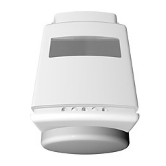
The radiator controller HR 80 is a component of the zoning system. It can be installed on all the common radiator valves. As the valve is a self contained unit, there is no risk of it causing any water leakage from your heating.
The set temperature can be changed...
- manually using the adjustment dial on the operating unit of the radiator controller
- with the command centre
Pack content

- Operating unit
- Coupling module
- Adapter Danfoss RA
- Batteries
- Caleffi adapter
Operating elements and display

- Display: Shows current set temperature and device information.
- Adjustment dial on the operating unit: Allows manual temperature adjustment.
- Symbol for the RF connection to the command centre.
- Symbol for separating the operating unit and coupling module.
- Set temperature
- Symbol for actual value coming from the command centre (optional).
Installation
- Remove the old thermostat.
Inserting/Changing batteries

- Open battery compartment (Fig. D).
- If necessary, remove empty batteries.
![]() Do not dispose of batteries with household trash. They must be returned in accordance with the local statutory requirements.
Do not dispose of batteries with household trash. They must be returned in accordance with the local statutory requirements.
![information]() Always replace both batteries. Only use 1.5 V alkaline batteries of the type LR06.
Always replace both batteries. Only use 1.5 V alkaline batteries of the type LR06. - Insert the new batteries into the battery compartment. Ensure that the polarity is correct!
- Close the battery compartment.
![information]() If the batteries were changed after a successful binding procedure,
If the batteries were changed after a successful binding procedure, ![]() appears in the display (see Section 2.5).
appears in the display (see Section 2.5).
 appears in the display (see Section 2.5).
Separating operating unit from the coupling module
- Turn the point of the locking knob (1) upward to open the lock. (Fig. E).
![]()
- Pull operating unit and coupling module apart from each other (Fig. F).


Installing coupling module
- Turn the adjustment dial (3) of the coupling module counterclockwise until the nose (1) of the adjustment dial is positioned at the stop (2) of the housing (Fig. G).

- Push coupling module onto the radiator valve (Fig. H).

- Slide metal knurled nut onto the threading of the radiator valve. (Fig. I)
![]()
- Tighten the metal knurled nut without using a tool (Fig. I).


Hint: The correct installation of the coupling module is best checked with the central heating switched on. If the coupling module is correctly installed, the radiator will become warm (adjustment dial positioned at the left-hand stop).
Checking valve lift
Prerequisite: The nose of the adjustment dial is positioned at the stop of the housing (Fig. G).
- Turn the adjustment dial of the coupling module (1) clockwise until resistance can be felt (Fig. J).
![]()
The spindle (2) of the coupling module is now touching the valve pin (3) of the radiator valve (4) (Fig. K).
![]()
- Turn the adjustment dial on the coupling module (1) clockwise until the final stop is reached (Fig. L).

The radiator valve is closed. With the central heating switched on, the radiator cools down.


 The valve lift between the left-hand stop (open) and the right-hand stop (closed) has to amount to at least ¾ of a rotation.
Activating binding procedure

The radiator controller communicates with the central operating unit via a wireless connection.
- When selecting the operating site ensure that the distance to wireless devices such as wireless headphones, cordless phones etc. is approx. 1–2 m according to the DECT standard.
New components of the zoning system must be assigned to the command centre before they can be taken into operation. This process is called the "binding procedure".
First read through all the steps for the complete binding procedure and then carry them out. The binding procedure mode remains active at the radiator controller for a maximum of 4 minutes.
- Position the operating unit directly near the corresponding coupling module.
- Press the binding procedure button (1, Fig. M) for approx. one second and then release it.

When releasing the button, the![]() symbol flashes in the display and the device number is displayed for 30 seconds.
symbol flashes in the display and the device number is displayed for 30 seconds.

If several radiator controllers are to be controlled simultaneously in one room:
- Press the binding procedure button on all the radiator controllers consecutively.
- Activate binding procedure at the command centre (see operating instructions of the command centre).
During binding procedure, the![]() symbol is shown continuously in the display of the radiator controller. The following is displayed:
symbol is shown continuously in the display of the radiator controller. The following is displayed: ![]() .
.
 .
.The radiator controller receives data from the command centre. This process can take up to 4 minutes.
Failed binding procedure
The binding procedure has failed if the ![]() symbol extinguishes. Take the following measures:
symbol extinguishes. Take the following measures:
- Remove the disturbing/shielding devices, e.g. wireless headphones, cordless telephones, loudspeakers, garage door openers.
- Repeat the binding procedure.
If the ![]() symbol extinguishes during normal operation, possible causes are discharged batteries at the command centre. You do not have to repeat binding operation, if the communication is reestablished. If you remove the batteries and insert them again, the HR80 goes direct in sync mode.
symbol extinguishes during normal operation, possible causes are discharged batteries at the command centre. You do not have to repeat binding operation, if the communication is reestablished. If you remove the batteries and insert them again, the HR80 goes direct in sync mode.
The set temperature at the radiator controller is automatically set to 20°C.
Finishing installation of radiator controller (Fig. N, O, P)
- Turn the retaining bracket on the operating unit until the tip points upwards (Fig. N).
![]()
The lock on the coupling module opens.
- Slide the operating unit onto the coupling module (Fig. O).
![]()
- Turn the retaining bracket to the side (Fig. P).
![]()
The operating unit and coupling module are connected firmly. The letter a, followed by three additional characters, appears in the display of the HR 80.
The adaptation enables the radiator controller to adjust to the lift stop on the radiator valve. The radiator controller is ready for operation.


Installing radiator controller onto another valve
Before screwing the radiator controller onto another valve:
- Separate the coupling module from the operating unit.
Each time the radiator controller is installed, the automatic adaptation enables it to adjust to the lift stop of the valve.
Operation
Every change in the set temperature remains valid until it is overwritten automatically by a time program.
The set temperature is controlled by the command centre and set there as well. For further information please refer to the operating instructions of the command centre.
Changing set temperature with adjustment dial
- Turn the adjustment dial of the operating unit until the desired set temperature (between 5 – 30°C) is displayed.
![information]() The range for the set temperature (standard range: 5 – 30°C) can be restricted at the command centre.
The range for the set temperature (standard range: 5 – 30°C) can be restricted at the command centre.
In order to open or close the radiator valve completely: - Turn the adjustment dial until "OFF" (closed) or "ON" (opened) is displayed.
Changing batteries
If  appears in the display, both batteries must be replaced.
If the batteries are too weak, the radiator controller opens the radiator valve completely.
If the batteries are replaced after the binding procedure has been completed,  is displayed.
The radiator controller waits for data from the command centre.
Emergency operation with empty batteries
- Separate operating unit from coupling module (Fig. E and F).
- Use the adjustment dial to open (in the direction of the plus sign) or close (in the direction of the minus sign) the heating valve manually (Fig. Q).
![]()

Automatic functions
Window function
If you open a window and the temperature drops sharply, the radiator controller closes the radiator valvein order to save energy.
The display then shows the message  .
.
When the temperature rises again, the radiator controller returns to normal operation, however at the latest after 30 minutes. The window function can be deactivated at the command centre.
Protection against valve malfunction
Once a week the radiator controller opens and closes the radiator valve automatically and thus protectsit against malfunction. The display then shows the message  .
.
Frost protection
If the temperature drops below 5°C, the radiator controller keeps the radiator valve at a constant 5°C.
The frost-protection value (standard value: 5°C) can be changed at the command centre.
The frost-protection function does not function when the batteries are empty or the operating unit is removed.
Manual adaptation
Manual adaptation can be used to solve various problems:
- if automatic adaptation does not work.
- if the entire valve lift is to be utilized.
- if the radiator hardly gets warm at all.
- if the radiator does not become cold.
- if the
![]() symbol is displayed (no adaptation possible).
symbol is displayed (no adaptation possible). - if the
![]() symbol is displayed (valve lift too short or motor cannot be moved).
symbol is displayed (valve lift too short or motor cannot be moved).
 symbol is displayed (no adaptation possible).
 symbol is displayed (valve lift too short or motor cannot be moved).
Activating manual adaptation
- Separate operating unit from the coupling module (Fig. E and F).
- Press the binding procedure button until
![]() is shown in the display.
is shown in the display. - Attach the operating unit to the coupling module (Fig. N, O and P).
![]() to
to ![]() are displayed.
are displayed.
The radiator controller carries out the manual adaptation.
 is shown in the display.
 are displayed.
 Reactivating automatic adaptation
If the HR 80 is to be switched back to automatic adaptation after a manual adaptation, the factory settings are to be restored:
- Separate operating unit from the coupling module (Fig. E and F).
- Remove the batteries.
- Press and hold the binding procedure button with a small screwdriver.
- Insert the batteries with the other hand.
- Attach the operating unit to the coupling module (Fig. N, O and P).
Displays aD-1 to aD-7appear.
The radiator controller carries out the automatic adaptation.
![information]() A new binding procedure must be carried out after activating automatic adaptation.
A new binding procedure must be carried out after activating automatic adaptation.
Installing additional devices or parts
The following adapters/coupling modules are available for Oventrop, Herz, Danfoss, Vaillant and Caleffi valves:
| Coupling module type | Order name |
| Oventrop HU 01 (Fig. Q) (knurled nut M30x1) | HU 01 |
Herz HU 02 (Fig. R) (knurled nut M28)  | HU 02 |
| Adapter type | |
| Danfoss adapter set EVA 1-Danfoss RAV (gray) (Fig. S)  RA (white) (Fig. T)  RAVL (black) (Fig. U)  | EVA 1-Danfoss (enclosed) |
Vaillant adapter EHA 1VAI (Fig. V) | EHA 1VAI |
Caleffi (Fig. W) | (enclosed) |
Installing adapter
- Select the required adapter.
- Open up the adapter and push it onto the valve as far as the stop.
Turn it while doing so until you feel it click into place.
If provided on the adapter: - Screw the adapter firm or insert the adapter pin.
Service mode (for installers only)
The wireless contact between the radiator controller, the command centre and a receiver unit is checked in Service mode.
- Separate operating unit from coupling module (see Section 2.2. Fig. F)
- Turn the adjustment dial until on (open) appears in the display.
- Turn adjustment dial two full rotations (720°) further. KesKis displayed. Service mode is active.
The radiator controller transmits a test message to any available receiver unit (e.g. HC60ng). - Press the binding procedure button.
The radiator controller is ready to receive the test message from the command centre.
The first two digits in the display indicate the number of received test messages, and the right-hand digit indicates the field strength (1 = sufficient field strength, 5 = very good field strength)
To deactivate Service mode:
- Press the binding procedure button for 5 seconds or wait 5 minutes or remove and then reinsert the batteries. Service mode is deactivated.
ROBINEX
Armaturen Robinetterie Rubinetterie
Bernstrasse 36, CH-4663 Aarburg/Oftringen Telefon 062 787 70 00, Fax 062 787 70 01 info@robinex.ch, www.robinex.ch

Documents / Resources
References

Download manual
Here you can download full pdf version of manual, it may contain additional safety instructions, warranty information, FCC rules, etc.
Advertisement
Thank you! Your question has been received!


Need Assistance?
Do you have a question about the HR 80 that isn't answered in the manual? Leave your question here.