Advertisement
Quick Links
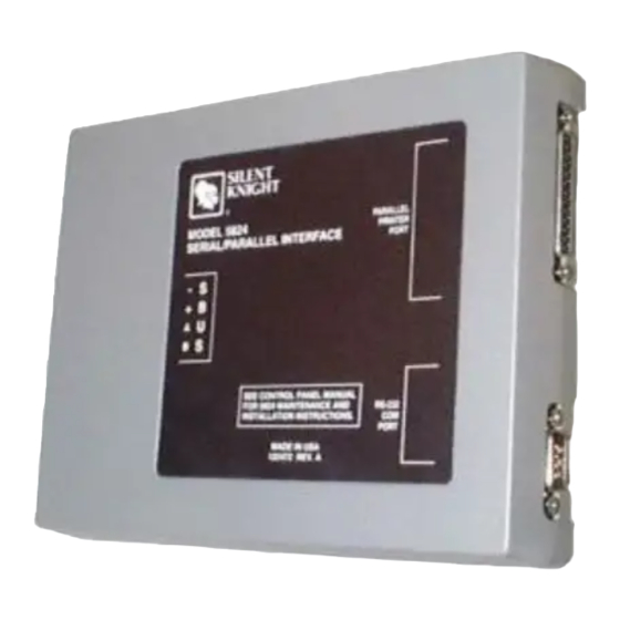
1 General
The 5824 Serial/Parallel Printer Interface Module connects a compatible
fire alarm control panel (FACP) directly to a printer to print event his-
tory, system event logs, and detector statuses. This document is for quick
reference. For more information, refer to the FACP installation manual.
NOTE: Installation and wiring of this device must be
done in accordance with NFPA 72 and local ordinances.
2 Specifications
Operating Voltage
24 VDC
Current
50mA
(Alarm and Standby)
Max Per FACP
Addressable FACPs qty 4; 5208 FACP qty 1
Operating Temperature
32°F to 120°F (0°C to 49°C)
Max Wiring Distance
6000 ft. (1829 m)
from FACP
Mounting
Surface
Dimensions
6"W x 7-3/4"H x 1-7/16"D
(15.2 cm W x 19.7 cm H x 3.7 cm D)
Parallel Port
Ancillary
Serial Port
Primary Fire Signaling
3 Mounting
The 5824 ships in a plastic enclosure which must be mounted inside the
annunciator or accessory cabinet.
To mount the 5824 plastic enclosure into the appropriate cabinet:
1.
Remove the 5824 cover. Use a small screwdriver if necessary.
2.
Remove the 5824 circuit board from the base by pushing outward
on the base snap retaining tabs and lifting out the circuit board.
5824 Serial/Parallel Printer Interface Module
Product Installation Document
PN 151392:G5 2/2/2022 151062
.
Figure 1 5824 Circuit Board And Plastic Base
3.
Mount the plastic base into the appropriate accessory cabinet.
4.
Replace the circuit board in the plastic base.
NOTE: It may be necessary to connect the wiring to the
circuit board before the board is replaced into the base.
4 Wiring to a FACP
Terminate the wiring as shown in the diagram and table below.
–
+
A
-
+ A B
circuit board
snap retaining tabs
S-
S+
A
B
FACP
SBus
Connector
B
-
+
A
B
5824
Figure 2 Wiring the 5824 to the FACP
base
Advertisement

Related Manuals for Honeywell 5824


Summary of Contents for Honeywell 5824
- Page 1 NOTE: It may be necessary to connect the wiring to the 3 Mounting circuit board before the board is replaced into the base. The 5824 ships in a plastic enclosure which must be mounted inside the 4 Wiring to a FACP annunciator or accessory cabinet.
- Page 2 5 Setting DIP Switches Each 5824 connected to a compatible FACP requires an ID number which is set using the DIP switches on the 5824 circuit board. Refer to the figure below to see how to position the DIP switches for the desired ID number.