Table of Contents
Advertisement
Quick Links
Advertisement
Table of Contents

Related Manuals for Honeywell FS24X Plus


Summary of Contents for Honeywell FS24X Plus
- Page 1 USER MANUAL Honeywell® FS24X Plus™ Advanced multi-spectrum 3IR Flame detector...
-
Page 2: Table Of Contents
Analog Output: Flame Detected Detector Module Replacement Configuration and Operation Test Lamp Operation Declaration of Conformity Maintenance FS24X Plus™ Material Numbers Product Label Appendix 1: Hazardous Location Installation for FS & SS Series Flame Detectors and Associated Test Lamps Honeywell®FS24X Plus™ | User Manual... - Page 3 Commissioning the Detector States & Outputs Test Lamps Maintenance Flame Response Sensitivity False Alarm Stimuli Response Appendix 3: Honeywell® FlameManager Install the Honeywell® FlameManager Application Appendix 4: HART® User Information EDD/DTM Access Levels and Password Protection Menu Structure Menu Navigation Error Reporting User Manual Honeywell®...
- Page 4 Command #166: Force 4-20 mA - Specific Loop Current Command #167: Force HALO State Command #168: Write mA Configuration Command #169: Configure Alarm, Warning State - Latch/Unlatch Command #173: Read HALO Mode for Normal Command #174: Set Date Format Honeywell®FS24X Plus™ | User Manual...
- Page 5 Command #197: Read LED Intensity Command #198: Read Serial Number Common-Practice Commands Tables Performance Appendix 6: Overview of the FS24X Plus™ Modbus Interface Appendix 7: Fault Conditions Appendix 8: Certifications and Approvals Hazardous Area Contact Us User Manual Honeywell® FS24X Plus™ |...
-
Page 6: Introduction
RISK OF IMPROPER FLAME DETECTION Install only in areas in accordance with the environmental and hazardous area ratings. Carefully review mounting area and position in accordance with the FS24X Plus™ FM Performance Appendix and this Manual to ensure optimal flame detection regarding the angle of device and unobstructed view. - Page 7 The detector may be damaged if external temperatures exceed 75ºC. Perform a Test Lamp test to assure proper function. The detector must be returned to Honeywell® for service if high-temperature shutdown occurs. CAUTION RISK OF VULNERABILITY IN NETWORKS The FSX Plus flame detectors may be vulnerable to a cyber-attack on the HART® and RS-485...
-
Page 8: Disclaimer
Disclaimer In no event shall Honeywell® be liable for any damages or injury of any nature or kind, no matter how caused, that arise from the use of the equipment referred to in this manual. Strict compliance with the safety procedures set out and referred to in this manual, and extreme care in the use of the equipment, are essential to avoid or minimize the chance of personal injury or damage to the equipment. -
Page 9: Copyright Notice
In no event is Honeywell® liable to anyone for any indirect, special or consequential damages. The information and specifications in this document are subject to change without notice. -
Page 10: Security Guide
FlameManager. Cybercriminals frequently display astonishing creativity. A flame detection system should be configured to resist attacks years in the future, during the equipment’s entire life cycle. The system should be regularly tested end-to-end. User Manual Honeywell® FS24X Plus™ |... -
Page 11: Specifications
FoV can extend to 120° (+/-60°). Field of View (Conical) for Standard Mount: Note: See Appendix 2: FS24X Plus™ FM Performance Appendix for FM 3260 FoV performance. EN 54-10 Field of View approved to symmetrical 90° (45° off axis EN 54-10 Field of View: horizontal and vertical rotation). - Page 12 Inrush Current is 0.75A for a maximum duration of less than 5ms. Aluminum 3 lbs. 11 oz. (1.7 kg) Weight: Stainless Steel 7 lbs. 7 oz. (3.4 kg) See Appendix 2: FS24X Plus™ FM Performance Appendix for details of specific fuels, detection distances, and false alarm immunity. Flame Detection Performance: Note that fire is random and chaotic.
- Page 13 SM4-M – marine version available. Diameter: 125 mm (4.92 in) x 115 mm (4.52 in) deep; Two M25 X 1.5P or two ¾ ’’ NPT conduit entries. Enclosure: Window size diameter: 79 mm (3.11 in) Honeywell®FS24X Plus™ | User Manual...
-
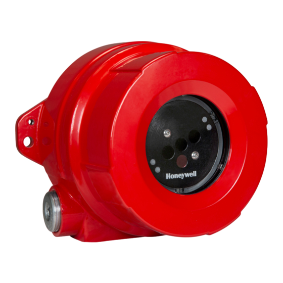
Page 14: Product Overview
Product Overview Honeywell® FS24X Plus™ is an advanced multi-spectrum electro-optical flame detector based on the WideBand IR technology which responds quickly to radiant energy created by flaming fires. It is suitable for operation in hazardous areas. The FS24X Plus™ flame detectors are factory calibrated and robust. There is no need of a field calibration. -
Page 15: Self-Test
Easy guided setup via HART®, RS-485 or USB / PC Application Simple test with test lamp Ease of Maintenance Simple bump test with Honeywell® long range test lamps (simply test at height) Built-in test diagnostics certified to IEC61508 Advanced window monitoring... -
Page 16: Installation And Commissioning
Install the detector on the SM4/SM4-M bracket using the two bolts provided. Note: We recommend angling all detectors down at least 40 degrees from horizontal. The SM4 and SM4-M mounts have marked angle graduations. Note: SM4-M is more resistant to vibration for marine or high-vibration applications. User Manual Honeywell® FS24X Plus™ |... -
Page 17: Opening The Detector
Loosen, but do not remove, the set screw on the enclosure lid (see Figure below): Turn counterclockwise (CCW) to unscrew the enclosure lid (see Figure below): Loosen the three captive screws on the detector module electronic device (see Figure below): Honeywell®FS24X Plus™ | User Manual... -
Page 18: Installation Summary
Configuration is done by USB or RS-485 with the PC application available from www.sps.honeywell.com. See Appendix 3: Honeywell® FlameManager section of this manual. This is easiest done prior to installation. Note: Refer to the fuel/sensitivity settings table to determine the correct configuration. -
Page 19: Wiring
When connecting to a fire panel, follow NFPA 72 standard. For duplicate terminals and leads for supervised relay connections to the fire alarm system, use p/n FS24XP-NFPA-KIT NFPA assembly kit include 6-pin two-row connector as well as 9-pin two-row connector. Honeywell®FS24X Plus™ | User Manual... - Page 20 Note: On power-up, the FS24X Plus™ flame detector will run a start-up routine during which current levels maybe not be stable. The controller should also be set to filter milliamp transients of less than 1 millisecond. User Manual Honeywell® FS24X Plus™ |...
- Page 21 The following diagrams show the mA wiring options: Honeywell®FS24X Plus™ | User Manual...
- Page 22 The mA Loop Wiring is shown for three wire source mode. Refer to the wiring diagram for details on other modes. General Notes on Shielding: Use of Shielded Twisted pairs with shield coverage of more than 80% is recommended. Open the shields for connection to the equipment or detector with minimum pigtail length possible. User Manual Honeywell® FS24X Plus™ |...
-
Page 23: Commissioning The Detector
4.5 mA for FMM-420 Module Interface Operation State Configurable Values are either 4.0 mA, 16.0 Fire Alarm State 16.0 mA 4.0 mA 20.0 mA mA or 20.0 mA Verified Fire 20.0 mA Not Configurable Alarm State User Manual Honeywell® FS24X Plus™ |... -
Page 24: Detector Module Replacement
Figure 4 in Opening the Detector section) WARNING: Do not touch the sensor array as finger oils interfere with infrared signal transmission. Tighten the 3 captive screws. Screw the cover onto the base enclosure. Tighten the set screw. Honeywell®FS24X Plus™ | User Manual... -
Page 25: Configuration And Operation
For testing, in compliance with best practice and NFPA 72 Codes for flame detectors, as manufacturers of the FSX Plus product line, tests are made using the Honeywell® TL-2055 Test Lamp with a range of 10-25 ft when fully charged. -
Page 26: Declaration Of Conformity
Inspect at least quarterly in dirty environments. Semi-annual or quarterly testing should be performed, using the appropriate Honeywell® Test Lamp, to ensure the integrity of the detector. A complete “end-to-end” test of the entire fire detection system should be performed periodically depending on the application. -
Page 27: Product Label
Product Label FS24X Plus™Flame detector will include the following label in the back of the electronic device: User Manual Honeywell® FS24X Plus™ |... -
Page 28: Appendix 1: Hazardous Location Installation For Fs & Ss Series Flame Detectors And Associated Test Lamps
Series Flame Detectors and Associated Test Lamps Overview The Honeywell® Flame Detectors and Test Lamps are hazardous area products. They are factory calibrated, and the robust sealed design with no moving parts allows for mounting in any orientation even in harsh environments. These products are available in either a 316 Stainless Steel or Low Copper Aluminum. -
Page 29: Nameplate Tag
Additional regional marks (such as South Korea and Russia) and installation specific marks (such as ABS) may also be present. See individual nameplates for specific approvals applicable to each product. Note: Some products require 18 in. of conduit. (See individual nameplate for specifics). Honeywell®FS24X Plus™ | User Manual... -
Page 30: Generic Nameplate View
FS10-R-A: Max 29 VDC, 120 mA; Relay 24 VDC, 1 A FS20X and FS24X Series: Max 32 VDC, 150 mA; Relay 24 VDC, 1 A FS20XP and FS24XP: Consumption 18 - 32 VDC, 500 mA max; Relay 24 VDC/AC, 2 A maximum User Manual Honeywell® FS24X Plus™ |... -
Page 31: Installing The Flame Detector
Note: Detector functionality and communication should be tested to confirm correct FoV and configuration in the final system. WARNING RISK OF EXPLOSION Do not connect test lamps to external power sources. Test lamps are battery operated only. Do not open when explosive gases are present. Charging permitted in safe environment only. Honeywell®FS24X Plus™ | User Manual... -
Page 32: Appendix 2: Fm Performance For Fs24X Plus
Appendix 2: FM Performance for FS24X Plus™ Product Overview The Honeywell FS24X Plus® is a hazardous area flame detector that uses 3IR sensors to respond quickly to a flaming fire. It is factory calibrated, and the robust sealed design with no moving parts allows for mounting in harsh environments. -
Page 33: Hazardous Classifications
Outputs: Fault, Alarm and Auxiliary SPDT relays Max. 32 Vdc/ac, max. 2 A, min 10mA at 12 V resistive load. 4-20 mA Source, sink or isolated current output. FP2 over RS-485 and USB (USB is accessible through Detector Module electronic device only). Modbus over RS-485. Honeywell®FS24X Plus™ | User Manual... - Page 34 Same energized Mostly off, Normal flashing Green Operation, No fire every 5 seconds Inhibited Solid Yellow Same Flashing Yellow Fault Same every second Alarm Solid Red Flashing Red Flashing Yellow Warning and Green Same Alternate User Manual Honeywell® FS24X Plus™ |...
-
Page 35: Available Accessories/Spares
SM4-M Marine Mounting Bracket NFPA 72 Connector Kit p/n FS24XP-NFPA-KIT Tank Mount What’s in the box? 1 Flame detector 1 FS24X Plus™ FM Performance Appendix 1 Standard Mount (SM4) or Marine Mount (SM4-M) 1 Threaded Stopping plug 1 Sunshade (SH-001) Installation Note: Must only be installed by appropriately trained and accredited personnel. -
Page 36: Wiring
NFPA 72 Terminal Blocks - When connecting to a fire panel, compliance with NFPA 72 is obtained by using the terminal blocks in NFPA 72 Connection Kit p/n FS24XP-NFPA-KIT. Instructions are provided with the kit and online (see QR code on the back of this appendix). User Manual Honeywell® FS24X Plus™ |... -
Page 37: Wiring Configurations
Wiring Configurations There are multiple ways to configure the current loop on the detector. Consult the User Manual for specifics on each of the methods shown below. Honeywell®FS24X Plus™ | User Manual... -
Page 38: Communication Wiring
The termination of the alarm circuit conductor and the EOL resistor (or the next unit in a daisy chain of units) must be inserted into separate openings on the duplicate terminal block of the NFPA 72 Connection Kit to comply with NFPA 72 requirements. User Manual Honeywell® FS24X Plus™ |... - Page 39 The termination of the alarm circuit conductor and the EOL resistor (or the next unit in a daisy chain of units) must be inserted into separate openings on the duplicate terminal block of the NFPA 72 Connection Kit to comply with NFPA 72 requirements. Honeywell®FS24X Plus™ | User Manual...
-
Page 40: Configure The Detector (Safe Area)
LED, 4-20 mA current loop, Relays, RS-485 Modbus, and HART® EDD over 4-20mA current loop. Test Lamps The Honeywell® TL-1055 and TL-2055 test lamps are compatible with the FS24X Plus™ flame detectors. Note that the test lamps will alarm the detector, so we recommend inhibiting the safety system before testing. -
Page 41: Maintenance
The detector is appropriately aimed at the fire threat area. The detector’s alarming circuitry and outputs (i.e., relays, 4-to-20 mA, etc.) function properly. Tests are made using the Honeywell® TL-2055 Test Lamp with a range of 10-25 ft when fully charged. -
Page 42: Flame Response Sensitivity
12 in X 12 in (0.3m X 75 ft Kerosene N/A*1 N/A*1 Very High 0.3m) (22m) 6 in X 6 in (0.15m X 100 ft JP-4 N/A*1 N/A*1 Very High 0.15m) (30m) Note: *1: Indoor testing not FM witnessed. User Manual Honeywell® FS24X Plus™ |... -
Page 43: False Alarm Stimuli Response
Typical distances for other sensitivities are metric, i.e. the ratios for Very High, High, Medium, and Low sensitivities are 100%, 75%, 50%, and 25%. FM witness testing included verifying all sensitivities for indoor/outdoor heptane. Honeywell®FS24X Plus™ | User Manual... - Page 44 Sodium Vapor Lamp, 70W >= 7 ft (Modulated) (2.2m) >= 5 ft 3 in X 3 in (76mm X 20 ft (6m) 80 ft (24m) (1.6m) 76mm) n- Heptane Sodium Vapor Lamp, 70W >= 5 ft (Un-Modulated) (1.6m) User Manual Honeywell® FS24X Plus™ |...
-
Page 45: Appendix 3: Honeywell® Flamemanager
CHAPTER Appendix 3: Honeywell® FlameManager Install the Honeywell® FlameManager Application Download and install the PC application. Minimum System Requirements: Microsoft Windows 10 or later. 32 or 64-bit version. Microsoft .NET framework version 4.6 or later. A USB port. A 1280 X 768 pixels or larger screen. - Page 46 1200 meters [4000 feet] and is faster if configured for the highest baud rate. It requires an RS-485 transceiver which most computers lack. Honeywell® does not sell RS-485 transceiver but has used Advantech BB-USOPTL4 extensively. This and similar devices can be purchased multiple distributors.
- Page 47 The program requires the presence of a file “HoneywellFlame.lic” in the “Documents” folder as shown below. This file can be obtained from Honeywell®. When this file is found successfully, the communications parameter form displays “License Status is OK” as shown in the Communications Parameters window.
- Page 48 Press [OK] to accept the change or [Cancel] to reject it. The Configure/Outputs tab has the controls shown below. Several rules restrict the setting of mA levels. Honeywell®FS24X Plus™ | User Manual...
- Page 49 However, the HART® event history report does not adjust for time zones. For installations utilizing this feature, setting the detector’s clock to local time may be more convenient. User Manual Honeywell® FS24X Plus™ |...
- Page 50 The Display Event History tab is shown below. Updating this list can be slow as the detector can store thousands of events. Frequent instances of Fault 2002 shown below is normal when operating the detector without 24 VDC power. Honeywell®FS24X Plus™ | User Manual...
- Page 51 The vertical bars on the side of the graph show the relative signal amplitude in a log scale. It is often useful to disable the DC graphs to reduce clutter. One of the buttons facilitates separating the DC and AC signals into different regions of the form. User Manual Honeywell® FS24X Plus™ |...
- Page 52 PC. When this is done, a form much like shown below will appear. The upload process takes a minute or more depending on the network used. The FirePic can be saved as a CSV file. This can be emailed to Honeywell® for analysis. Honeywell®FS24X Plus™ | User Manual...
- Page 53 18 and 8 seconds before the alarm are self-test signals. The last tab is Update Firmware and it is shown below. This facilitates improving the performance of existing flame detectors in the field. Firmware update is only permitted over the USB interface. User Manual Honeywell® FS24X Plus™ |...
-
Page 54: Appendix 4: Hart® User Information
The FS24X Plus™ user interface recognizes three login profiles. Default profile ‘Guest’ offers limited access rights. The second profile ‘Engineer’ is available to wider engineering personnel. The third profile ‘Honeywell® Engineer’ is restricted to Honeywell®Field Service personnel. The default ‘Guest’ profile is read-only and displays information about the current gas leak reading and detector status, including active warnings and faults. -
Page 55: Menu Structure
XXXX 8 Serial Number XXXX 1 PV Current Loop 2 Poll addr 3 Device Overview 3 Tag 4 Long tag 9 HART 5 Descriptor 6 Message 7 Loop Current Mode 8 Configure HART® 9 HART® Parameters Honeywell®FS24X Plus™ | User Manual... - Page 56 1 Detector Status 1 Operations 2 Inhibit 2 Diagnostics 3 Sensitivity 3 Event History Sensitivity 4 4-20 mA Loop 4 Settings Change Sensitivity 5 State Latch 5 Account 6 LED 6 Field Engineer Data 7 Relays User Manual Honeywell® FS24X Plus™ |...
- Page 57 6 Field Engineer Data 7 Relays 1 Operations 1 Change Password ???? 2 Diagnostics 2 Set Time (24-hour) ???? 3 Event History 3 Set Date ???? 4 Settings 4 Set Date Format ???? 5 Account 6 Field Engineer Data Honeywell®FS24X Plus™ | User Manual...
- Page 58 10 Near IR Band AC Value 5 Account 11 Visible Band DC Value 6 Field Engineer Data 12 Visible Band AC Value 13 5V Rail 14 3V3 Rail 15 AINCOM 16 UV Sensor Reading 17 Channel Status User Manual Honeywell® FS24X Plus™ |...
-
Page 59: Menu Navigation
For example, provided there is the minimum resistance of 250Ω in the 4-20 mA loop, the HART®handheld device can be connected across the terminals in the junction box. CAUTION If using multi-drop mode, the mA output cannot be used to provide a functional safety rated output signal. Honeywell®FS24X Plus™ | User Manual... -
Page 60: Appendix 5: Hart® Developer Information
Command #3 returns PV, units, and Loop Current. The first (PV) and the last (Loop Current) variables are same. Command #14 contains serial number of the device (3 bytes), followed by measurement units (1 byte) and 3 floating point variables for max, min, and span loop current in mA. User Manual Honeywell® FS24X Plus™ |... -
Page 61: Device-Specific Commands
Configure HALO Mode for Alarm Read HALO Mode for Alarm Read Alarm, Warning State - Latch / Unlatch Start / End Inhibit Read Inhibit Timeout Configure Inhibit Timeout Read mA Configuration Read Force Timeout Configure Force Timeout Write Login Honeywell®FS24X Plus™ | User Manual... -
Page 62: Additional Device Status (Command #48)
Not used Not used Power Supply Conditions Voltage Fault Out of Range Not used Not used Not used *Not used* bits are always set to 0. In each case, bit #0 is the low-order bit. User Manual Honeywell® FS24X Plus™ |... -
Page 63: Command #128: Read Fire Alarm Status
Invalid Selection Error Parameter Too Large Error Parameter Too Small Error Too few data bytes received Error Transmitter Specific Command Error Error Write Protect Mode 8-15 Undefined Error Access Restricted 17-31 Undefined Error Busy 33-127 Undefined Honeywell®FS24X Plus™ | User Manual... -
Page 64: Command #130: Read Device Status
Invalid Selection Error Parameter Too Large Error Parameter Too Small Error Too few data bytes received Error Transmitter Specific Command Error Error Write Protect Mode 8-15 Undefined Error Access Restricted 17-31 Undefined Error Busy 33-127 Undefined User Manual Honeywell® FS24X Plus™ |... -
Page 65: Command #135: Read Inhibit Status
Invalid Selection Error Parameter Too Large Error Parameter Too Small Error Too few data bytes received Error Transmitter Specific Command Error Error Write Protect Mode 8-15 Undefined Error Access Restricted 17-31 Undefined Error Busy 33-127 Undefined Honeywell®FS24X Plus™ | User Manual... -
Page 66: Command #136: Simulate 4-20 Ma
Invalid Selection Error Parameter Too Large Error Parameter Too Small Error Too few data bytes received Error Transmitter Specific Command Error Error Write Protect Mode 8-15 Undefined Error Access Restricted 17-31 Undefined Error Busy 33-127 Undefined User Manual Honeywell® FS24X Plus™ |... -
Page 67: Command #137: Read Internal Commination Fault Status
Invalid Selection Error Parameter Too Large Error Parameter Too Small Error Too few data bytes received Error Transmitter Specific Command Error Error Write Protect Mode 8-15 Undefined Error Access Restricted 17-31 Undefined Error Busy 33-127 Undefined Honeywell®FS24X Plus™ | User Manual... -
Page 68: Command #138: Read Voltage Fault Status
Invalid Selection Error Parameter Too Large Error Parameter Too Small Error Too few data bytes received Error Transmitter Specific Command Error Error Write Protect Mode 8-15 Undefined Error Access Restricted 17-31 Undefined Error Busy 33-127 Undefined User Manual Honeywell® FS24X Plus™ |... -
Page 69: Command #139: Read Test Lamp Detection Status
Invalid Selection Error Parameter Too Large Error Parameter Too Small Error Too few data bytes received Error Transmitter Specific Command Error Error Write Protect Mode 8-15 Undefined Error Access Restricted 17-31 Undefined Error Busy 33-127 Undefined Honeywell®FS24X Plus™ | User Manual... -
Page 70: Command #140: Read Temperature
Request Data Bytes Byte Format Description None Response Data Bytes Byte Format Description Float Voltage Command-Specific Response Codes Code Class Description Success No Command-Specific Errors Undefined Error Access Restricted 9-15 Undefined Error Access Restricted 17-127 Undefined User Manual Honeywell® FS24X Plus™ |... -
Page 71: Command #142: Read All Sensor Readings
36-39 Visible Band AC VALUE 40-43 5V Monitoring 44-47 3V3_Safe Monitoring 48-51 AINCOM Monitoring 52-55 UV Count 56-59 u32_channel_status Command-Specific Response Codes Code Class Description Success No Command-Specific Errors Undefined Error Access Restricted 9-15 Undefined Error Access Restricted 17-127 Undefined Honeywell®FS24X Plus™ | User Manual... -
Page 72: Command #144: Read Model
Command #153: Read Device Alarm State Reads the Device Alarm State. Request Data Bytes Byte Format Description None Response Data Bytes Byte Format Description [0] - Device Alarm Status 0 - Alarm2 Enum 1 - Alarm1 4 - None User Manual Honeywell® FS24X Plus™ |... -
Page 73: Command #154: Set Detector Sensitivity
Invalid Selection Error Parameter Too Large Error Parameter Too Small Error Too few data bytes received Error Transmitter Specific Command Error Error Write Protect Mode 8-15 Undefined Error Access Restricted 17-31 Undefined Error Busy 33-127 Undefined Honeywell®FS24X Plus™ | User Manual... -
Page 74: Command #155: Read Detector Sensitivity
Invalid Selection Error Parameter Too Large Error Parameter Too Small Error Too few data bytes received Error Transmitter Specific Command Error Error Write Protect Mode 8-15 Undefined Error Access Restricted 17-31 Undefined Error Busy 33-127 Undefined User Manual Honeywell® FS24X Plus™ |... -
Page 75: Command #158: Set Relay Default State
Invalid Selection Error Parameter Too Large Error Parameter Too Small Error Too few data bytes received Error Transmitter Specific Command Error Error Write Protect Mode 8-15 Undefined Error Access Restricted 17-31 Undefined Error Busy 33-127 Undefined Honeywell®FS24X Plus™ | User Manual... -
Page 76: Command #159: Read Relay Default State
Error Write Protect Mode 8-15 Undefined Error Access Restricted 17-31 Undefined Error Busy 33-127 Undefined Command #161: Reset Latch Resets Latch. Request Data Bytes Byte Format Description None Response Data Bytes Byte Format Description None User Manual Honeywell® FS24X Plus™ |... -
Page 77: Command #162: Set Password
Invalid Selection Error Parameter Too Large Error Parameter Too Small Error Too few data bytes received Error Transmitter Specific Command Error Error Write Protect Mode 8-15 Undefined Error Access Restricted 17-31 Undefined Error Busy 33-127 Undefined Honeywell®FS24X Plus™ | User Manual... -
Page 78: Command #164: Read Event History
Invalid Selection Error Parameter Too Large Error Parameter Too Small Error Too few data bytes received Error Transmitter Specific Command Error Error Write Protect Mode 8-15 Undefined Error Access Restricted 17-31 Undefined Error Busy 33-127 Undefined User Manual Honeywell® FS24X Plus™ |... -
Page 79: Command #165: Force Relay State
Busy 33-127 Undefined Command #166: Force 4-20 mA - Specific Loop Current Force 4-20mA - Specific Loop Current Request Data Bytes Byte Format Description Float mA Current Response Data Bytes Byte Format Description Float mA Current Honeywell®FS24X Plus™ | User Manual... -
Page 80: Command #167: Force Halo State
Invalid Selection Error Parameter Too Large Error Parameter Too Small Error Too few data bytes received Error Transmitter Specific Command Error Error Write Protect Mode 8-15 Undefined Error Access Restricted 17-31 Undefined Error Busy 33-127 Undefined User Manual Honeywell® FS24X Plus™ |... -
Page 81: Command #168: Write Ma Configuration
Write mA Configuration. Request Data Bytes Byte Format Description Enum State Enum Latch Enable or Disable Response Data Bytes Byte Format Description 0 - Warning Enum 1 - Alarm1 2 - Alarm2 Enum Latch Enable or Disable Honeywell®FS24X Plus™ | User Manual... -
Page 82: Command #173: Read Halo Mode For Normal
Invalid Selection Error Parameter Too Large Error Parameter Too Small Error Too few data bytes received Error Transmitter Specific Command Error Error Write Protect Mode 8-15 Undefined Error Access Restricted 17-31 Undefined Error Busy 33-127 Undefined User Manual Honeywell® FS24X Plus™ |... -
Page 83: Command #174: Set Date Format
Request Data Bytes Byte Format Description Integer Time or Date selection for change 1-10 ASCII Time 11-18 ASCII Date Response Data Bytes Byte Format Description Integer Time or Date selection for change 1-10 ASCII Time 11-18 ASCII Date Honeywell®FS24X Plus™ | User Manual... -
Page 84: Command #176: Read Rtc (Time And Date)
Invalid Selection Error Parameter Too Large Error Parameter Too Small Error Too few data bytes received Error Transmitter Specific Command Error Error Write Protect Mode 8-15 Undefined Error Access Restricted 17-31 Undefined Error Busy 33-127 Undefined User Manual Honeywell® FS24X Plus™ |... -
Page 85: Command #177: Configure Halo Mode For Alarm
Access Restricted 17-31 Undefined Error Busy 33-127 Undefined Command #178: Read HALO Mode for Alarm Reads HALO Mode for Alarm. Request Data Bytes Byte Format Description None Response Data Bytes Byte Format Description Integer LED Mode Honeywell®FS24X Plus™ | User Manual... -
Page 86: Command #179: Read Alarm, Warning State - Latch/Unlatch
Invalid Selection Error Parameter Too Large Error Parameter Too Small Error Too few data bytes received Error Transmitter Specific Command Error Error Write Protect Mode 8-15 Undefined Error Access Restricted 17-31 Undefined Error Busy 33-127 Undefined User Manual Honeywell® FS24X Plus™ |... -
Page 87: Command #180: Start/End Inhibit
Write Protect Mode 8-15 Undefined Error Access Restricted 17-31 Undefined Error Busy 33-127 Undefined Command #181: Read Inhibit Timeout Read Inhibit Timeout. Request Data Bytes Byte Format Description None Response Data Bytes Byte Format Description Integer Inhibit Timeout Honeywell®FS24X Plus™ | User Manual... -
Page 88: Command #182: Configure Inhibit Timeout
Invalid Selection Error Parameter Too Large Error Parameter Too Small Error Too few data bytes received Error Transmitter Specific Command Error Error Write Protect Mode 8-15 Undefined Error Access Restricted 17-31 Undefined Error Busy 33-127 Undefined User Manual Honeywell® FS24X Plus™ |... -
Page 89: Command #183: Read Ma Configuration
Invalid Selection Error Parameter Too Large Error Parameter Too Small Error Too few data bytes received Error Transmitter Specific Command Error Error Write Protect Mode 8-15 Undefined Error Access Restricted 17-31 Undefined Error Busy 33-127 Undefined Honeywell®FS24X Plus™ | User Manual... -
Page 90: Command #187: Read Force Timeout
Access Restricted 17-31 Undefined Error Busy 33-127 Undefined Command #188: Configure Force Timeout Configure Force Timeout Period. Request Data Bytes Byte Format Description Integer Force Timeout Response Data Bytes Byte Format Description Integer Force Timeout User Manual Honeywell® FS24X Plus™ |... -
Page 91: Command #189: Read Relay State
Invalid Selection Error Parameter Too Large Error Parameter Too Small Error Too few data bytes received Error Transmitter Specific Command Error Error Write Protect Mode 8-15 Undefined Error Access Restricted 17-31 Undefined Error Busy 33-127 Undefined Honeywell®FS24X Plus™ | User Manual... -
Page 92: Command #190: Write Login
Error Invalid Password 17-31 Undefined Error Busy 33-127 Invalid Login Level Command #191: Read Date Format Reads Date Format. Request Data Bytes Byte Format Description None Response Data Bytes Byte Format Description Enum Date Format User Manual Honeywell® FS24X Plus™ |... -
Page 93: Command #192: Read Relay3 (Aux) Input Selection
Invalid Selection Error Parameter Too Large Error Parameter Too Small Error Too few data bytes received Error Transmitter Specific Command Error Error Write Protect Mode 8-15 Undefined Error Access Restricted 17-31 Undefined Error Busy 33-127 Undefined Honeywell®FS24X Plus™ | User Manual... -
Page 94: Command #193: Set Relay3 (Aux) Input Selection
Undefined Error Busy 33-127 Undefined Command #195: Set Alarm Verification Time Set Alarm Verification Time. Request Data Bytes Byte Format Description Enum Alarm Verification Time Response Data Bytes Byte Format Description Enum Alarm Verification Time User Manual Honeywell® FS24X Plus™ |... -
Page 95: Command #196: Write Led Intensity
Invalid Selection Error Parameter Too Large Error Parameter Too Small Error Too few data bytes received Error Transmitter Specific Command Error Error Write Protect Mode 8-15 Undefined Error Access Restricted 17-31 Undefined Error Busy 33-127 Undefined Honeywell®FS24X Plus™ | User Manual... -
Page 96: Command #197: Read Led Intensity
Invalid Selection Error Parameter Too Large Error Parameter Too Small Error Too few data bytes received Error Transmitter Specific Command Error Error Write Protect Mode 8-15 Undefined Error Access Restricted 17-31 Undefined Error Busy 33-127 Undefined User Manual Honeywell® FS24X Plus™ |... -
Page 97: Command #198: Read Serial Number
The Following common-practice commands are implemented: Command Description Reset " Configuration Changed" Flag Read Additional Device Status The Command #48 returns 2 bytes of data. Supported Commands This Field Device does not support Burst Mode, Catch Device Variable or any device-specific. Honeywell®FS24X Plus™ | User Manual... -
Page 98: Tables
1 mA 4 mA Non-Optical Fault 1 mA 4 mA Alarm 20 mA 4 mA Operating Mode Power On Non-Recovery Fault Inhibit Alarm Fault Warning Normal Alarm Verified Alarm Login Level Dafault Level 1 Level 2 User Manual Honeywell® FS24X Plus™ |... -
Page 99: Performance
Modes Fixed current mode is implemented, using Loop current mode (Enable – Point to Point / Disable- Multi-drop). This mode is not cleared by power loss or reset. Write-protection and User controllable Damping are not supported. Honeywell®FS24X Plus™ | User Manual... -
Page 100: Appendix 6: Overview Of The Fs24X Plus™ Modbus Interface
Additionally, each byte can have one or two stop bits with a default of one stop bit. These parameters are set on the Configure/Fieldbusses tab of Honeywell® FlameManager . After the settings are changed, the detector must be rebooted before they take effect. The Modbus interface is implemented entirely as holding registers as listed in Table1. - Page 101 0x0200 reserved for future use 0x0400 Always on 0x0800 Relay 3 is warning instead of alarm2 0x1000 reserved for future use 0x2000 reserved for future use 0x4000 reserved for future use 0x8000 reserved for future use Honeywell®FS24X Plus™ | User Manual...
-
Page 102: Appendix 7: Fault Conditions
Over Temperature (> 75° C or 167° F). Under Temperature (< -55° C or -67° F). One or more Microprocessor Failures. One or more Relay Coil Failures. Communication Fault. Electronic Self-Test Failure. Dirty Window Lens Sensor failures. User Manual Honeywell® FS24X Plus™ |... -
Page 103: Appendix 8: Certifications And Approvals
II 2 D Ex tb IIIC, T 135°C Db IP66/67 Ta = -55°C to +85°C ATEX - FM14ATEX0058X IECEx - FMG14.0027X UK - FM21UKEX0035X Brazil - DNV18.0088X Others: INMETRO (Brazil) Marine certificates (Pending): ABS, Lloyds, BV, DNV Environmental EMC, WEEE, and RoHS Compliant User Manual Honeywell® FS24X Plus™ |... - Page 104 EN54-10: Class 1 (medium, high, and very high sensitivities). Class 2 (low sensitivity). CPR (EN 54-10:2002) EU 2831-CPR-F4713 UKCA 0832-UKCA-CPR-F1388 BRE Approval (EN 54-10:2002). Approval Number: 1175a/03 设计模板 - 中国 RoHS 2 限制材料表 产品: 含铅焊料和含铅探测器的pcb产品 提交者: 沙巴鲁丁.易卜拉欣 提交日期: 2021年8月24日 设计授权地址: 林肯郡 Honeywell®FS24X Plus™ | User Manual...
- Page 105 Questo simbolo indica che il prodotto non deve essere trattato come rifiuto industriale o domestico. Questo prodotto deve essere smaltito in idonei impianti di smaltimento specifici per RAEE. Per ulteriori informazioni sullo smaltimento di questo prodotto contattare l’ente locale preposto, il distributore o il produttore. User Manual Honeywell® FS24X Plus™ |...
- Page 106 Hausmüll oder kommunaler Müll entsorgt werden darf. Es sollte zum Recycling zu einer geeignete WEEE Entsorgungsanlagen gegeben werden. Um weitere Informationen zum Recycling dieses Produkts zu erhalten wenden Sie sich an Ihre Kommunalbehörde, Ihren Lieferanten oder den Hersteller. Honeywell®FS24X Plus™ | User Manual...
-
Page 107: Contact Us
Tel: +1 847 955 8200 www.honeywell.com Toll free: +1 800 538 0363 Fax: +1 847 955 8210 detectgas@honeywell.com Europe, Middle East, and Africa Honeywell® International Sarl Z.A. La Piece 16 1180 Rolle Switzerland Main Phone: +41 21 695 30 00 reception.rolle@honeywell.com Asia Pacific Honeywell®...