Table of Contents
Advertisement
Quick Links
Advertisement
Table of Contents

Related Manuals for Honeywell NOTIFIER UDS-3


Summary of Contents for Honeywell NOTIFIER UDS-3
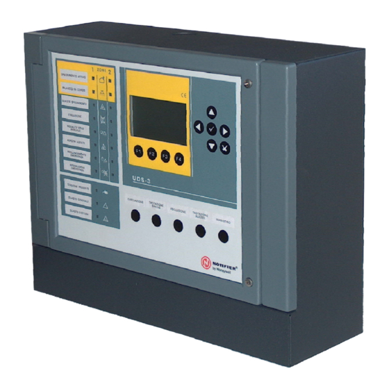
- Page 1 Installing and UDS-3 Operating manual Release panel...
- Page 2 __________________________________________________________________________ 5 ERMINALS DESCRIPTION OF OUTPUTS ASSIGNED TO EACH UDS-3 EXTINGUISHING ZONE _______________ 9 _________________________________________________________________________ 11 OMMANDS SIGNALLING _______________________________________________________________________ 13 KEYS DESCRIPTION ________________________________________________________________ 14 FUNCTION KEYS ___________________________________________________________________ 15 ___________________________________________________________________ 15 ORMAL CONDITION _______________________________________________________________ 16 PERATING CONDITIONS ________________________________________________________ 16 ACTIVATED UNIT CONDITION ___________________________________________________________ 16 CTIVATED UNIT CONDITION _________________________________________________________ 16...
- Page 3 POWER SUPPLY CHART _____________________________________________________________ 36 FRONT PANEL CHART_______________________________________________________________ 36 MAIN BOARD CHART ________________________________________________________________ 37 ABSORPTION CALCULATION _________________________________________________________ 38 PAGE - 2 Installation and operating manual UDS-3 NOTIFIER ITALIA Doc. M-205.1-UDS3N-ENG Rev A.1 UDS-3_manu...
-
Page 4: General Description
UDS-3 is a control panel for any extinguishing systems: inert gas, CO , water, dust, foam etc. The new extinguishing management panel UDS-3 manages two discharge zones according to UNI EN 12094-1; each zone has dedicated input and output lines. UDS-3 has a metallic box with LCD display to allow easy plant status view and different password level protected keyboard for programming and local plant management. -
Page 5: Electrical Features
Environmental conditions Operating temperature: - 5° C / + 40° C. Relative humidity: 10% - 93% (without condensate). Storing temperature: -10°C / +50°C UDS-3 Power The control panel is powered by mains and, when missing, it can still work thanks to inside fitted batteries. Mains characteristics are: ... - Page 6 Grounding Grounding must be consistent with CEI and ISPELS rules and must have a resistance less than 10 Ohm (measured at the grounding well without loads). Grounding cable must be connected to the control panel on the CNA terminal board. Protection grade IP30 Weight...
- Page 7 CNZ1 Zone 1 connections Notes Alarm input 1 Termination resistance 2,7K (for connections see p. 23) Alarm input 2 Termination resistance 2,7K (for connections see p. 23) Manual extinguishing activation input Termination resistance 2,7K (for connections see p. 23) Emergency delay input Termination resistance 2,7K...
- Page 8 CNZ2 Zone 2 connections Notes Alarm input 1 Termination resistance 2,7K (for connections see p. 23) Alarm input 2 Termination resistance 2,7K (for connections see p. 23) Manual extinguishing activation input Termination resistance 2,7K (for connections see p. 23) Emergency delay input Termination resistance 2,7K...
-
Page 9: I N P U T D E S C R I P T I On
For each input in the terminal board, the following “activation window” is valid. The only exception is for Flowmeter and Manostat inputs that can have the alarm window instead of the stand-by one (for NA or NC inputs) depending on the program. All inputs are balanced with an end-line 2,7K-1/4W resistor. - Page 10 DESCRIPTION OF OUTPUTS ASSIGNED TO EACH UDS-3 EXTINGUISHING ZONE PRE-ALARM DEVICE OUTPUT Controlled output with a 2,7K-1/4W End-Of-Line resistor. This output can be used to drive other devices of the extinguishing system, and it’s activated by a pre-alarm signal. Being controlled, it’s particularly suitable for optical warning devices connections or for optical/acoustic devices connection.
- Page 11 FAULT EXTINGUISHING PLANT OUTPUT (UNIT BLOCKED/ZONE EXCLUDED) This is a controlled output with an End-Of-Line 2,7K-1/4W resistance. This output is activated if during UDS-3 standby state an extinguishing loss condition happens, caused by manostat input activation; UDS-3 goes in “agent loss fault” and shows the “Low pressure” fault, or it is activated when the associated zone is manually excluded from the “exclusions”...
- Page 12 UDS-3 control panel has two analog loop inputs to manage signals dedicated to analog control panels, one loop for each zone. Each extinguishing zone is interfaced with the analog control panel through emulation with two output modules and 4 input modules (six for each zone, twelve in total for both). CNL1 terminal board is dedicated to analog loop input for zone 1 command and signals.
- Page 13 Buzzer acoustic signalling is activated when one of the following happens: 1. in presence of the pre-activation signal, coming from terminal board or loop, buzzer acoustic signal is silenced automatically if the pre-alarm cause is removed, bringing UDS-3 back to standby mode. 2.
- Page 14 SIGNALLING EXTINGUISHING ACTIVE (red) Blinking with a single alarmed input (pre-activation condition). ON fixed with two inputs of the same zone in alarm (Activation condition) RELEASE IN PROGRESS (red) ON fixed when the output is active (extinguisher release). EXTINGUISHING FAULT (yellow) Blinking when one of the following inputs is in fault condition: ALL1 and ALL2, Manual extinguishing activation, emergency extension, only manual, emergency interruption, manostat, Flowmeter...
-
Page 15: Keys Description
KEYS DESCRIPTION Keys to use: DURING PROGRAMMING or to INSERT PASSWORD ARROWS: used for selections. ENTER: after making a selection, confirms data ESCAPE: “back”, erases the last introduced data or gets out of the menu FUNCTION KEYS: these keys activate the corresponding displayed function. These keys change in function of the selected menu. -
Page 16: Function Keys
FUNCTION KEYS Function keys allow programming menu access and status visualization for each releasing zone. They are near display’s lower border and are active during visualization of UDS-3 main screen. F1 (MENU) It allows to access main menu for UDS-3 programming and configuration. F2 (INFO) It allows accessing the visualization screen for extinguishing condition, faults, and exclusions events in zone 1. -
Page 17: Operating Conditions
Operating conditions Pre-activated unit condition In presence of an activation signal on one of the two inputs zone 1 and zone 2 (for control panel connection) or for pre-activation signal coming from analog loop. UDS-3 shows this condition by: active buzzer ... - Page 18 Release condition UDS-3 enters this condition when it gets a signal from flowmeter input or after pre-release period (if programmed). In this state, UDS-3 activates extinguishing output and manages release cycle, checking flowmeter and manostat input. This condition is indicated by: ...
- Page 19 Manual activation Analog loop activation Terminal board input activation In case of activation, extinguishing output is not operated, neither common output for release in progress condition, but only sounder output. Only whether an activation signal was present on the flowmeter input, UDS-3 gets into release status, enabling also extinguishing outputs [UNI EN 12094-1 4.15.1].
- Page 20 Pressing F1 (MENU) function key, a list of sub menus that allow initial system configuration is shown in order to modify programming. See Programming Menu paragraph See Configuration Menu See Manual mode Menu See Test Menu See Utilities Menu PAGE - 19 Installation and operating manual UDS-3 NOTIFIER ITALIA...
-
Page 21: Programming Menu
Programming menu To get into this menu you need to insert a 4 level password (default one is 44444) enabling hardware programming key on the front panel (J1 jumper in A position, see installation manual, “Front board mapping” chapter). To insert the password see editing function explained in “keyboard operation for data insertion” paragraph. Choosing “Program”... -
Page 22: Configuration Menu
Extinguishing output activation time programming. You can set the following timings: 2 seconds 60 seconds 150 seconds 10 minutes Enabling flowmeter control (Flow ctrl.: YES) This input activation indicates that extinguishing release is in progress. If flowmeter output activates during standby condition, it means that extinguishing has not been started by UDS-3 panel but by an external device (for example a manual activation of the rapid flow valve). -
Page 23: Manual Mode Menu
Manual mode menu Selecting “Manual mode” sub-menu (with 2 level password) it’s possible to access “MANUAL” or “AUTOMATIC” modes settings for each zone. Manual mode selection makes it possible to activate extinguishing system only with a signal coming from a manual activation. - Page 24 To modify one or more data into Date and Time programming screen, use 4 keys to select the field to change (selected field’s characters are in white on a dark background). Use keys to modify data and enter key to store the new one. N.B.: date and time are reset to zero in case of UDS-3 power loss.
-
Page 25: Network Connection
Panel must be fixed to the wall in order to Furthermore, if the panel needs to be clearly visible and easily accessed by be wall-mounted near a corner, operators. For example a 1,5m height fits minimum advised distance is well for display sight. 180mm in order to allow front panel opening. - Page 26 1 - Open general 230Vac power switch of the plant 3 - Connect power cable to CNA terminal board 5 – Close mains switch 6 – Install and connect batteries as shown in this manual N.B.: the control panel automatically starts when connected to the power. It is necessary to wait a few hours in order to wait for the batteries to be filled by mains.
- Page 27 CNZ1 For flowmeter and manostat inputs you can set contact-type (NC-NO) for standby mode from CNZ2 programming menu. For Manostat and Flowmeter inputs it’s possible to configure contact topology (NO-NC) for standby state from programming menu. PAGE - 26 Installation and operating manual UDS-3 NOTIFIER ITALIA Doc.
- Page 28 Connection scheme for solenoids on “Extinguishing zone 1” output Recommended connection Connection scheme for solenoids on “Extinguishing zone 2” output Recommended connection N.B.: polarities shown in terminals are to be referred to Standby condition of UDS-3 PAGE - 27 Installation and operating manual UDS-3 NOTIFIER ITALIA Doc.
- Page 29 Connection scheme for “Sounder zone 1” output Recommended connection for not Recommended connection for polarized sounders. polarized sounders. Connection scheme for “Sounder zone 2” output Recommended connection for not Recommended connection for polarized sounders. polarized sounders. N.B.: polarities shown in terminals are to be referred to Standby condition of UDS-3 PAGE - 28 Installation and operating manual UDS-3...
- Page 30 Connection schemes for “Zone1 pre-alarm” output. Recommended connection Recommended connection for not polarized actuators. for polarized actuators. Connection schemes for “Zone2 pre-alarm” output. Recommended connection Recommended connection for not polarized actuators. for polarized actuators. N.B.: polarities shown in terminals are to be referred to Standby condition of UDS-3 PAGE - 29 Installation and operating manual UDS-3...
- Page 31 Connection schemes for “Extinguishing Plant Block zone1” output Recommended connection Recommended connection for not polarized actuators. for polarized actuators. Connection schemes for “Extinguishing Plant Block zone2” output Recommended connection Recommended connection for not polarized actuators. for polarized actuators. N.B.: polarities shown in terminals are to be referred to Standby condition of UDS-3 PAGE - 30 Installation and operating manual UDS-3...
- Page 32 Connection schemes for “Pilot bottle/Directional valve zone1” output Recommended connection Recommended connection for not polarized actuators. for polarized actuators. Connection schemes for “Pilot bottle/Directional valve zone2” output Recommended connection Recommended connection for not polarized actuators. for polarized actuators. N.B.: polarities shown in terminals are to be referred to Standby condition of UDS-3 PAGE - 31 Installation and operating manual UDS-3...
- Page 33 Outputs in common to zone 1 and 2 N.B. do not connect remote commands like telephone diallers to this output since the output line is not controlled PAGE - 32 Installation and operating manual UDS-3 NOTIFIER ITALIA Doc. M-205.1-UDS3N-ENG Rev A.1 UDS-3_manu...
- Page 34 Flowchart of conditions that activate output dedicated to signalling and release One input in Pre-activated condition is alarm zone bypassed if release condition is commanded by manual activation device. Two inputs in the same alarm zone If release is not immediate because a pre-release time is set or emergency extension device is active, output will have a pulsing activation...
- Page 35 Extinguishing cycle flowchart Release activation is performed if: both inputs from conventional control panel are active; both pre-alarm inputs are given by the analog control panel; manual activation input is active Only if release delay time is different from 0 seconds Release inhibition causes: emergency...
- Page 36 UDS-3 installation must be performed after reading carefully instructions indicated in this manual. After mechanical installation, follow these instructions: Choose the right batteries, check autonomy that plant must grant in case of 230Vac mains loss Connect UDS-3 panel to 230Vac mains with a tri-polar cable: phase, neutral and ground (ground conductor must be longer than the other two) and must be fixed with a small band to the case so that it can’t be pulled off accidentally Mains connection must be done respecting the following:...
- Page 37 POWER SUPPLY CHART FRONT PANEL CHART PAGE - 36 Installation and operating manual UDS-3 NOTIFIER ITALIA Doc. M-205.1-UDS3N-ENG Rev A.1 UDS-3_manu...
- Page 38 MAIN BOARD CHART PAGE - 37 Installation and operating manual UDS-3 NOTIFIER ITALIA Doc. M-205.1-UDS3N-ENG Rev A.1 UDS-3_manu...
- Page 39 ABSORPTION CALCULATION Active condition Standby condition Consumption Consumption CONTROL PANEL UDS-3 0.100 One zone = 0.220 Two zones = 0.300 Sounder output connected |_________| devices |_________| Pre-alarm output connected devices Release fault output connected devices Discharge done output |_________| connected devices Directional valves output |_________| connected devices...
- Page 40 E-mail: notifier@notifier.it A Honeywell company Every care has been taken in the preparation of this data sheet but no liability can be accepted for the use of the information therein. Design features may be changed or amended without prior notice.