janitza UMG 96-PQ-L User Manual And Technical Data
Power analyzer
Hide thumbs
Also See for UMG 96-PQ-L:
- Installation manual (12 pages) ,
- User manual and technical data (120 pages) ,
- Installation manual (12 pages)

Related Manuals for janitza UMG 96-PQ-L


Summary of Contents for janitza UMG 96-PQ-L
- Page 1 Power Analyzer UMG 96-PQ-L (from firmware 1.0 - hardware index 1) User manual and technical data Janitza electronics GmbH Vor dem Polstück 6 D-35633 Lahnau Support tel. +49 6441 9642-22 Email: info@janitza.de www.janitza.de...
- Page 2 UMG 96-PQ-L www.janitza.de UMG 96-PQ-L (from firmware 1.0 / hardware index 1) Measurement device for recording energy quantities Doc. no.: 2.061.073.2.c Date: 08/2021 The German version is the original edition of the documentation...
- Page 3 Nonetheless, we wish to point out that updates of this document are not always possible at the same time as technical refinements are implemented in our products. Please see our website under www.janitza.de for the current version. Please see our website under www.janitza.de for the current version.
-
Page 4: Table Of Contents
UMG 96-PQ-L www.janitza.de TABLE OF CONTENTS 1. Information on the device and the user manual ........8 1. - Page 5 UMG 96-PQ-L 6. Grid systems ..............26 7.
- Page 6 UMG 96-PQ-L www.janitza.de 12. Configuration ..............46 12.
- Page 7 UMG 96-PQ-L 13. 15 Configuration of the analog output ..........76 13.
-
Page 8: Information On The Device And The User Manual
We ask for your understanding for these manual. simplifications. · This user manual applies to the UMG 96-PQ-L. Separate validities and distinctions are marked. · First make sure you have read and understood the usage information accompanying the prod- uct. -
Page 9: Defective Device/Disposal
· When doing so, please bear the terms for trans- portation in mind. INFORMATION Please return defective or damaged devices to Janitza electronics GmbH in accordance with the shipping instructions for air or road freight (complete with accessories). Observe special regulations for devices with built-in... -
Page 10: Safety
UMG 96-PQ-L www.janitza.de Safety Hazard levels The chapter on Safety contains information which must be observed to ensure your personal safety Warning and safety information is marked by a and avoid material damage. warning symbol, and the hazard levels are shown... -
Page 11: Product Safety
UMG 96-PQ-L Product safety WARNING The device reflects current engineering practice Risk of injury due to electrical voltage! and accepted safety standards, but hazards can Severe bodily injury or death can result! Therefore arise nonetheless. please abide by the following: ·... -
Page 12: Electrically Qualified Personnel
UMG 96-PQ-L www.janitza.de Electrically qualified personnel Safety information for handling current transformers and measurement devic- To avoid bodily injury and material damage, only es with residual current measurement electrically qualified personnel are permitted to work on the devices and their components, mod-... -
Page 13: Handling Batteries/Accumulators
The battery used in the device may cause fire or burns if used improperly. · Only replace the battery with the same type or types recommended by Janitza! · Observe the polarity when installing the battery! · Remove batteries only with non-conductive tools (e.g. -
Page 14: Product Description
You can distinguish between the UMG 96-PQ-L It can be assumed that safe operation is no longer and the UMG 96-PQ-L in the IT variant by the possible if the device, for example: part number. The part number can be found on ·... -
Page 15: Intended Use
UMG 96-PQ-L Intended use The device is: · Only for use in the industrial sector. · Intended for installation in switchboard cabinets and small installation distributors. · Not intended for installation in vehicles! Use of the device in non-stationary equipment consti- tutes an exceptional environmental condition and is only permissible by special agreement. -
Page 16: Performance Characteristics
0.5 for ../1 A transformer · Connect the device and the radio/television · Reactive energy class 1 receiver in different circuits. · if necessary, contact Janitza support or a radio/ Measurement television technician. · Acquisition of more than 800 measured values ·... -
Page 17: Scope Of Delivery
UMG 96-PQ-L / 52.32.xxx · All supplied options and design variants are UMG 96-PQ-L (IT variant) described on the delivery note. 33.03.389 Installation instructions The following apply for the battery used in the device: 33.03.342 Supplement “Safety Information”... -
Page 18: Measuring Method
(download at ® · Continuously and calculates all effective values www.janitza.de) is the perfect tool for the configu- using in a 200 ms interval. ration, readout and analysis of measurement data. · The true RMS value (TRMS) of the voltages and currents applied to the measuring inputs. - Page 19 UMG 96-PQ-L...
-
Page 20: Structure Of The Device
UMG 96-PQ-L www.janitza.de Structure of the device Front panel - Display and controls Tab. Front view UMG 96-PQ-L Item Function/Designation Button 1: · Display Menu · Exit Menu · Cancel action (ESC) Button 2: · Go to the start screen. (Default setting: “Summary” display) ·... -
Page 21: Rear Of The Device - Connections
UMG 96-PQ-L Rear of the device - Connections Tab. Rear view UMG 96-PQ-L Item Function/Designation Voltage measurement inputs V 1 to V 3 and V N Supply voltage RS-485 interface Digital inputs Digital outputs Analog outputs Module connector socket Current measurement inputs I1 to I3 Tab.: Rear of the device - Connections... -
Page 22: Rating Plate
10H • 000 1234567 XXXX/XXXX Aux: 90..277V, 50/60Hz 90..250V 4,5VA 300V CAT III Made in Germany • www.janitza.com Item Designation Description · Supply voltage, AC in V · Nominal frequency in Hz Operational data · Supply voltage, DC in V ·... - Page 23 UMG 96-PQ-L...
-
Page 24: Mounting
Ground conductive switchboards! ATTENTION Material damage due to disregard of the instal- lation instructions! Tab. Mounting orientation of the UMG 96-PQ-L Disregard of the installation instructions can (rear view) damage or destroy your device. · Observe the information on the mounting orientation in the sections “Mounting”... -
Page 25: Securing
· Before inserting the device, remove the fastening clips (e.g. with a screwdriver) by levering them horizontally. Tab. Side view of UMG 96-PQ-L with fastening clip. · Guide the device through the switchboard (mounting plate) from the front. -
Page 26: Grid Systems
· IT networks (IT variant - part number: You can distinguish between the UMG 96-PQ-L 5236005). and the UMG 96-PQ-L in the IT variant by the part number. The part number can be found on · Residential and industrial areas. -
Page 27: Installation
Tab. Nominal network voltages suitable for measuring inputs death or to material damage! according to EN 60664-1:2003 (valid in three-phase · Do not use the outputs of the Janitza measure- 4-conductor systems with grounded neutral conductor ment devices or their components for switching - see section “Grid systems”). -
Page 28: Three-Phase Three-Conductor System
UMG 96-PQ-L www.janitza.de 7.3.1 Three-phase three-conductor system Operation of the device requires a supply voltage. The type and level of the supply voltage for your Networks and nominal voltages suitable for your device can be found on the rating plate. Also note: device: ·... - Page 29 UMG 96-PQ-L Overcurrent protective device for the line pro- tection of the supply voltage PE/FE Recommendation for the overcurrent protective device of the supply voltage line protection (depen- 1) Fuse (UL/IEC listed) dent on the device variants): 2) Isolation device (disconnect switch or ·...
-
Page 30: Voltage Measurement
UMG 96-PQ-L www.janitza.de Voltage measurement There are 3 voltage measurement inputs (V1 to V3) on the rear of the device. 7.4.1 Overvoltage The voltage measurement inputs are suitable for measurement in networks where overvoltages of category 600 V CAT III (rated surge voltage 6 kV) can occur. -
Page 31: Connection Variants For Voltage Measurement
UMG 96-PQ-L Fig.: INFORMATION Voltage measurement in a three-phase 3-conduc- · The device only determines measured values if a tor system with voltage voltage L1-N of greater than 20 V (4-conduc- transformer. tor measurement) or a voltage L1-L2 of greater... -
Page 32: Current Measurement
UMG 96-PQ-L www.janitza.de Current measurement WARNING The device: Risk of injury due to electrical voltage at current · Is designed for the connection of current trans- transformers! formers with secondary currents of ../1 A and ../5 Current transformers which are operated exposed on the secondary side can carry haz- ·... -
Page 33: Current Direction
UMG 96-PQ-L 7.5.1 Current direction 7.5.3 Ammeter You can correct the current direction for each If you want to measure the current not only with phase individually via the serial interfaces pro- the UMG, but also with an ammeter, connect the vided. -
Page 34: Connection Variants For Current Measurement
UMG 96-PQ-L www.janitza.de 7.5.4 Connection variants for current measurement Fig.: Fig.: Current measurement Current measurement via current transformer via current transform- in a three-phase 4-con- er in a three-phase ductor system 3-conductor system Load Load Fig.: Fig.: Current measurement Current measurement... - Page 35 UMG 96-PQ-L...
-
Page 36: Connection And Pc Connections
RS-485 RS-232 RS-485 PC with GridVis ® UMG 96-PQ-L RS-485 RS-485 1. Use of the UMG 96-PQ-L (server device) via a UMG with gateway functionality (e.g. UMG 512 client device): PC with GridVis ® Ethernet Ethernet UMG 512-PRO as gateway... -
Page 37: Interface
UMG 96-PQ-L RS-485 interface Shielding The device communicates with the Modbus RTU Provide a twisted and shielded cable for connec- protocol via an RS-485 interface (3-pole plug tions via the interfaces and observe the following contact). points for shielding: ·... -
Page 38: Termination Resistors
UMG 96-PQ-L www.janitza.de Termination resistors Bus structure At the beginning and end of a segment, the cable In a bus structure: is to be terminated with resistors (120 Ω, 1/4 W). · Connect all devices in line. · Each device has its own address. - Page 39 UMG 96-PQ-L Tab. Representation of a bus structure * Client device Server device Server device Server device Repeater Server device Server device Server device Server device Power supply necessary Client device - e.g. UMG 604-PRO Bus terminator on Server device - UMG 96PA In a Modbus system the Modbus organization (modbus.org) uses the terms “client”...
-
Page 40: Digital Inputs And Outputs
UMG 96-PQ-L www.janitza.de Digital inputs and outputs The device has: External auxiliary voltage 24 VDC · 3 digital inputs and · 3 digital outputs UMG 96-PQ-L Digital inputs Digital inputs 1-3 The device has three digital inputs for the connec- tion of, for example, one signal generator each. -
Page 41: Digital Outputs
UMG 96-PQ-L Digital outputs External auxiliary voltage 24 VDC The device has 3 digital outputs, which: · Are electrically isolated from the evaluation elec- tronics via optocouplers. UMG 96-PQ-L · Have a common reference. · Are not short-circuit proof. -
Page 42: Analog Outputs
UMG 96-PQ-L www.janitza.de 10. Analog outputs The device has 1 passive analog output which can deliver a current of 0 - 20 mA. An external power supply unit (24 V DC) is required for operation. The connectable load must not exceed a resis- tance of 300 ohms. -
Page 43: Operation
11.2 Measuring display “Summary” The device is operated via 6 function buttons which have different functions: Start screen, UMG 96-PQ-L: After restoration of network power, the UMG 96- · Selecting measuring displays. PQ-L starts with the measuring display Summary. · Navigation within the menus. -
Page 44: Overview Of Menu Displays
11.4 Overview of menu displays Drag indicator Current Menu Current L1 Overview Current L2 (UMG 96-PQ-L start screen - default setting) Current L3 Active power Voltage Active power L1 Voltage L-N (3P4W network only) Active power L2 Voltage L-L Active power L3 History Active power L1 .. -
Page 45: Configuring A New Start Screen
Device address Baud rate INFORMATION Data frame Measurement · Ex works, the UMG 96-PQ-L has the Pass- word 00000 (no password). Transformer · The measurement device locks the device con- Connection variant figuration for 10 min. if the password is entered incorrectly 5 times. -
Page 46: Configuration
UMG 96-PQ-L www.janitza.de 12. Configuration 12.1 The Configuration window 12.2 Language The Configuration menu of the device contains all Use the Language item of the Configuration parameters in which you make settings. The de- window to configure the language for the device's vice requires the supply voltage for configuration. - Page 47 UMG 96-PQ-L · Data frame: Select a uniform data framework for all devices in the bus structure. Setting range: · “odd” (parity odd , with 1 stop bit) · “even” (parity even, with 1 stop bit) · “1 stop bit” (parity none, with 1 stop bit).
-
Page 48: Measurement
UMG 96-PQ-L www.janitza.de 12.4 Measurement · The Measurement window appears with the settings for the current and voltage transformers In the “Measurement” menu, configure the ratio (primary and secondary). of the current and voltage transformers (primary to secondary side), the connection variants, the nominal current and the nominal frequency. -
Page 49: Connection Variant
UMG 96-PQ-L 12.4.2 Connection variant · Open the Configuration window as previously described. · Use buttons 3 () and 4 () to select the item Measurement and confirm with button 6 (Enter). · The Measurement window appears. · Use buttons 3 () and 4 () to select the item... -
Page 50: Nominal Current
UMG 96-PQ-L www.janitza.de Connection variant 3w2m 12.4.3 Nominal current For a defined operation of the device, you need the nominal current in addition to the settings of the current and voltage transformer ratios. · Open the Configuration window as previously described. -
Page 51: Nominal Frequency
UMG 96-PQ-L 12.4.4 Nominal frequency To determine the mains frequency, the measure- ment device requires a voltage > 20 (4-wire Vrms The device requires the mains frequency for the measurement) or a voltage L1-L2 > 34 (3-wire Vrms measurement and calculation of measured values. -
Page 52: Display
UMG 96-PQ-L www.janitza.de 12.5 Display · Confirm your entries with button 6 (Enter) or end the action by pressing button 1 (Esc). Use the item Display of the measurement device to · To return to the start screen, press button 1 twice configure the following display settings: (Esc) and then press button 2 (Home). -
Page 53: Colors
UMG 96-PQ-L 12.6 System 12.5.4 Colors In the System window, the user of the measure- Colors for the display of current and voltage in the ment device can: graphical visualizations. · View device-specific system settings. · Configure a password. -
Page 54: Firmware/Serial Number
00000 = without password (-1/+1). · Confirm your entries with button 6 (Enter) or end The UMG 96-PQ-L is delivered ex works with the action by pressing button 1 (Esc). the password 00000 (no password) configured. · To return to the start screen, press button 1 twice For a password change, you need the current (Esc) and then press button 2 (Home). -
Page 55: Reset
UMG 96-PQ-L 12.6.4 Reset Minimum and maximum values This function is used to delete and reset measured With this function, the device user deletes all min. values and device parameters. and max. values in the device simultaneously. It is not possible to select certain energy meters. - Page 56 UMG 96-PQ-L www.janitza.de Standard factory settings Restart This function resets all settings, such as configura- This function restarts the measurement device. tions and recorded data, to the factory settings. · Open the Configuration window as previously · Open the Configuration window as previously described.
-
Page 57: Modbus Editor
(Modbus address 30001): Modbus Measured value You can use the Modbus address list (download address at www.janitza.de) to configure the analog output 19026 Active power, sum L1-L3, instantaneous value of the measurement device, for example, via the device keyboard. Reactive power, sum L1-L3, instantaneous... - Page 58 UMG 96-PQ-L www.janitza.de You can access the Modbus editor as follows: Example for the measured value Active power: · Open the Configuration window as previously described. · In the Configuration window, select the item · Use buttons 3 () and 4 () to select the item Modbus editor and confirm with button 6 (Enter).
- Page 59 UMG 96-PQ-L...
-
Page 60: Commissioning
UMG 96-PQ-L www.janitza.de 13. Commissioning 13.1 Applying the supply voltage WARNING 1. Connect the supply voltage with a terminal on Risk of injury due to electrical voltage! the back of the device. If the device is exposed to surge voltages above 2. -
Page 61: Frequency
UMG 96-PQ-L 13.4 Frequency For the measurement and calculation of measured values, the device requires the nominal or mains frequency. The mains frequency can either be specified by the user or determined automatically by the device. · To determine the mains frequency, the voltage... -
Page 62: Fundamentals On The Phasor Diagram
UMG 96-PQ-L www.janitza.de 13.5.1 Fundamentals on the phasor diagram Representation of capacitance: The phasor diagram graphically describes the · The current is ahead of the voltage. phase shift or phase angle between the voltage · The phase shift of an “ideal capacitor” is 90°. -
Page 63: Checking Of Voltage And Current Inputs By Means Of Phasor Diagram
UMG 96-PQ-L 13.6 Checking of voltage and current inputs 13.7 Overrange by means of phasor diagram If the measuring range is exceeded, a warning The phasor diagram can be used to check incor- appears in the device display, e.g. for the voltage, rect connections at the voltage and current inputs. -
Page 64: Control Of The Power Measurement
UMG 96-PQ-L www.janitza.de 13.9 Control of the power measurement 13.10 Control of the communication Short-circuit all current transformer outputs except The device counts all received (RX), all sent (TX) one and check the indicated powers. and all faulty data packets. - Page 65 UMG 96-PQ-L Now check the RS-485 communication parame- ters, such as: · All received (RX), all sent (TX) and all faulty data packets. Ideally, the number of errors in the col- umn Error will equal “0”. · The mode that is set, the device address, baud rate and timeout.
-
Page 66: Delete Min./Max. Values
UMG 96-PQ-L www.janitza.de 13.11 Delete min./max. values · The submenu for Voltage appears. · In the submenu, select the item Voltage L-N with In the measuring displays for voltage, current and buttons 3 () and 4 () and confirm with button power, the device offers the function of deleting 6 (Enter). - Page 67 UMG 96-PQ-L...
-
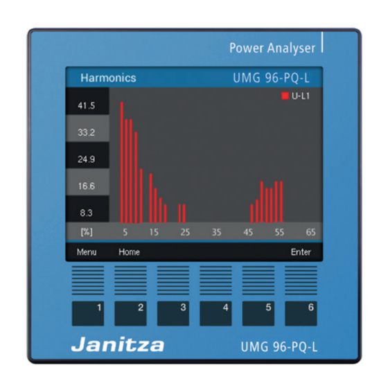
Page 68: Harmonics Current (Harmonics)
45 - 65 Hz. The calculated harmonics of the voltages and currents refer to this fundamental oscillation. The UMG 96-PQ-L calculates harmonics up to 65 times the fundamental oscillation. · If you are not in the start screen, you can go to this view by pressing button 2 (Home). -
Page 69: Communication In The Bus System
The “response” of the device can then look as none (1 stop bit) follows: none (2 stop bits) Designation Hex Comment Stop bits (UMG 96-PQ-L): 1 / 2 External stop bits: 1 / 2 Device address Address=1 Function Number formats... -
Page 70: Digital Inputs/Outputs
® · The GridVis software is available for download ® Function mode (On/Off mode) from our website (www.janitza.de). A separate function can be assigned to each digi- tal input: 13.14.1 Digital inputs · Digital input 1: Configuration as tariff switching (HT/LT). - Page 71 UMG 96-PQ-L Pulse counter Measured value calculation: All digital inputs can be operated with a frequency of 25 Hz. The pulse duration (pulse width) and the Measured value = pulse x pulse valency pulse pause must be greater than 20 ms.
-
Page 72: Digital Outputs
UMG 96-PQ-L www.janitza.de 13.14.2 Digital outputs Pulse valency The pulse valency indicates how much energy (Wh Different functions can be assigned to the 3 digital or varh) corresponds to one pulse. outputs: The pulse valency is determined by the maximum ·... - Page 73 UMG 96-PQ-L 3. Calculate pulse valency: Max. connected load [Pulses/Wh] Pulse valency = Max. number of pulses/h Pulse valency = 135 kW / 60000 pulses/h Pulse valency = 0.00225 pulses/kWh Pulse valency = 2.25 pulses/Wh External 230 VAC operating voltage...
- Page 74 UMG 96-PQ-L www.janitza.de Output for comparator group Two comparator groups (comparator 1 and 2) each with 3 comparators (A - C) are available for moni- toring limit values. The results of comparators A to C can be linked with “AND” or “OR”.
- Page 75 UMG 96-PQ-L Comparator running time Comparator running times are time counters that Measured value add up continuously for a set comparator output. This means that if the condition of the compara- Limit value tor is fulfilled and the lead time has expired, the...
-
Page 76: Configuration Of The Analog Output
UMG 96-PQ-L www.janitza.de 13.15 Configuration of the analog output “Peripherals”. Examples: The device has an analog output that can output a Allocation of active power L1 maximum current of 20 mA. (output range 4 - 20 mA) An external 24 VDC power supply unit is required for operation. -
Page 77: Drag Indicator Function
UMG 96-PQ-L 13.16 Drag indicator function Capture time: The individually configurable Capture time de- The “Drag indicator” function describes the 3 scribes a time window in which an incoming highest average values of value types over a pulse synchronizes the point in time. If the device defined period (time base). -
Page 78: External Synchronization
UMG 96-PQ-L www.janitza.de 13.16.2 External synchronization “One pulse” If the device receives a pulse or a Modbus com- An external synchronization for the calculation of mand once outside the capture time, the mea- the 3 highest average values is performed: sured values added up to that point are reset for ·... - Page 79 UMG 96-PQ-L “Periodic pulses” Scenario “Pulse before time base, within the capture time”: If the device receives periodic pulses via digital input 3 or periodic Modbus commands, there are · Perform value calculation now. different scenarios. · The time is set to 0 (new relative zero point).
-
Page 80: Synchronization Priority
UMG 96-PQ-L www.janitza.de 13.16.3 Synchronization priority Configura- Modbus Function tion address An external synchronization takes place according range to different priorities: Set trigger flag for 0 .. 1 drag indicator synchronization · Priority 1: Time base in seconds 60 .. 65535... -
Page 81: Drag Indicator - Measurement Device Displays
UMG 96-PQ-L 13.16.4 Drag indicator - Measurement device displays As already described in section “13.16 Drag indi- cator function”, the drag indicator function shows the 3 highest average values of value types over a defined period (time base). The drag indicators of the respective measured value types can be called up on the measurement device display under Menu >... -
Page 82: Delete Drag Indicator
UMG 96-PQ-L www.janitza.de 13.16.5 Delete drag indicator In each drag indicator display of the device - cur- rent, active and apparent power - a dialog box for deleting the drag indicator values appears when button 6 is pressed: Tab. Dialog box for deleting the drag indicator values... -
Page 83: Recordings
UMG 96-PQ-L 13.17 Recordings Recording 1 On a time base of 15 minutes, the measurement The standard setting of the measurement device device records the following measured values: includes 2 recording profiles that you can adapt or expand in the GridVis software. -
Page 84: Tariff Switching
UMG 96-PQ-L www.janitza.de 13.18 Tariff switching INFORMATION The recording of electrical energy values (active, Configure tariff switching using the GridVis ® reactive and apparent energy) is done via internal software! meters for two tariffs each. Switching between the tariffs (HT/LT) is supported ·... -
Page 85: Alarms For "Low Battery Voltage" And "Set Time
UMG 96-PQ-L 13.19 Alarms for “Low battery voltage” and After a battery replacement, an alarm appears on “Set time” the device display stating “Please set time”. NOTE The device: · Sets the time to the factory setting when the supply voltage is disconnected and the... -
Page 86: Overview Of Measuring Displays
UMG 96-PQ-L www.janitza.de 14. Overview of measuring displays Menu (summary) Network analysis (Start screen) Three-phase 4-conductor system Display of Three-phase 3-conductor system Display of · Voltage L1-N, L2-N, L3-N, frequency; · Voltage L1-L2, L2-L3, L3-L1, frequency; · Current L1, L2, L3 and sum of L1..L3;... - Page 87 UMG 96-PQ-L Menu (Current) Current THD-I Display of current L1, L2, L3 and their min. / Display of distortion factors for the current max. values (THD-I) L1, L2, L3 and their min. / max. values History Display of current histories L1, L2, L3...
- Page 88 UMG 96-PQ-L www.janitza.de Tariff Menu (Energy) Active, reactive, apparent energy Displays the sum (L1..L3) of active, reactive and Displays sum (L1..L3) of active, reactive and apparent energy according to tariffs apparent energy Menu (consumption overview) Active, reactive, apparent energy / Daily...
- Page 89 UMG 96-PQ-L Menu (drag indicator) Current Voltage L1, L2, L3 Drag indicator display of the currents L1, L2 and L3 with the 3 maximum values and a time stamp. Active power Active power (Appl. and Del.) L1, L2, L3 Active power sum (Appl.
- Page 90 UMG 96-PQ-L www.janitza.de Menu (Harmonics) Voltage L1 / L2 / L3 Voltage L1 / L2 / L3 Display of the harmonics up to the 65th harmonic Display of the harmonics up to the 65th harmon- (voltage L1, L2, L3) ic (current L1, L2, L3)
- Page 91 UMG 96-PQ-L Menu (System Info) For information on the items in the Configu- ration window, see section „12. Configura- tion“ on page 46 Submenu System Info Com. RS-485 Peripherals Display of received (RX), transmitted (TX) and Display of the states of the digital inputs and outputs, value of the analog output.
-
Page 92: Overview Of Configuration Displays
UMG 96-PQ-L www.janitza.de 15. Overview of configuration displays Menu (Configuration) For information on the items in the Configu- ration window, see section „12. Configura- tion“ on page 46 Language Setting the language to German. Setting the language to English. Communication Fieldbus settings device address, baud rate and data frame. - Page 93 UMG 96-PQ-L Display Settings for brightness, standby time after, bright- Settings for the display colors of voltage and ness (standby) and the display colors for voltage current (L1, L2, L3). and current (L1, L2, L3). System Firmware version, serial number. Setting the Resetting of energy measured values, min.
-
Page 94: Service And Maintenance
UMG 96-PQ-L www.janitza.de 16. Service and maintenance 16.3 Service Prior to outbound delivery, the device is subjected to various safety tests and is marked with a seal. For questions not answered or described in this If a device is opened, the safety tests must be re- manual, please contact the manufacturer. -
Page 95: Clock/Battery
UMG 96-PQ-L 16.6 Clock/Battery The supply voltage supplies the internal clock of the meter. If the supply voltage fails, the battery takes over the supply of voltage to the clock. The clock provides date and time information, for ex- ample for recordings and min. -
Page 96: Procedure In The Event Of A Malfunction
UMG 96-PQ-L www.janitza.de 17. Procedure in the event of a malfunction Failure mode Cause Remedy No display External fuse for the supply voltage has Replace fuse. tripped. No current display. No measured voltage connected. Connect measured voltage. No measured current connected. -
Page 97: Technical Data
UMG 96-PQ-L 18. Technical data General Net weight (with attached plug-in connectors) approx. 250 g (0.55 lbs) Package weight (incl. accessories) approx. 500 g (1.1 lbs) Battery Type Lithium CR2032, 3 V, (UL 1642 approved) Data memory 64 MB... - Page 98 UMG 96-PQ-L www.janitza.de Voltage measurement Three-phase 4-conductor systems with rated voltages up to 417 V / 720 V (+-10%) according to IEC 347 V / 600 V (+-10%) according to UL Three-phase 3-conductor systems with rated voltages up to 600 V (+10%)
- Page 99 UMG 96-PQ-L Analog outputs External power supply max. 33 V Current 0 .. 20 mA Update time Load max. 300 Ω Resolution 10 bit Connecting capacity of the terminals (supply voltage) Connectible conductors. Only connect one conductor per terminal point! Single core, multi-core, fine-stranded 0.2 - 4.0 mm...
-
Page 100: Performance Characteristics Of Functions
UMG 96-PQ-L www.janitza.de 19. Performance characteristics of functions Function Symbol Accuracy class Measuring range Display range Total active power (IEC61557-12) 0 W .. 12.6 kW 0 W .. 999 GW * Total reactive power QA, Qv 1 (IEC61557-12) 0 var .. 16.6 kvar 0 var .. - Page 101 UMG 96-PQ-L...
-
Page 102: Modbus Addresses Of Frequently Used Measured Values
UMG 96-PQ-L www.janitza.de 19.1 Modbus addresses of frequently used measured values Address Format RD/WR Variable Unit Comment 19000 float _ULN[0] Voltage L1-N 19002 float _ULN[1] Voltage L2-N 19004 float _ULN[2] Voltage L3-N 19006 float _ULL[0] Voltage L1-L2 19008 float _ULL[1]... -
Page 103: Number Formats
UMG 96-PQ-L Address Format RD/WR Variable Unit Comment 19096 float _IQH[1] varh Reactive energy, inductive, L2 19098 float _IQH[2] varh Reactive energy, inductive, L3 19100 float _IQH_SUML13 varh Reactive energy L1..L3, ind. 19102 float _CQH[0] varh Reactive energy, capacitive, L1... -
Page 104: Dimensional Drawings
UMG 96-PQ-L www.janitza.de 19.4 Dimensional drawings · The figures are for illustration purposes only and are not to scale. 96 mm 3.78 in Battery 96 mm 3.78 in Tab. Front view 1) Bottom view +0,8 3.62 +0.03 87,2 mm 6 mm 3.43 in... -
Page 105: Connection Example 1
UMG 96-PQ-L 19.5 Connection example 1 - S1 Data GND 15 16 Analog Digital inputs Digital outputs RS485 output UMG 96-PQ-L Supply voltage Voltage measurement Current measurement 11 12 13 PE/FE 230V/400V 50Hz 1) UL/IEC approved overcurrent protective device... - Page 106 Tel.: +49 6441 - 9642-0 Fax: +49 6441 - 9642-30 Email: info@janitza.de info@janitza.de | www.janitza.de Doc. no. 2.061.073.2.c | Date 08/2021 | Subject to technical changes. The latest version of the document can be found in the download area at www.janitza.de.