janitza UMG 96-PA User Manual
Power quality analyzer
Hide thumbs
Also See for UMG 96-PA:
- User manual and technical data (116 pages) ,
- User manual and technical specifications (98 pages) ,
- Installation instructions manual (16 pages)
Table of Contents

Related Manuals for janitza UMG 96-PA


Summary of Contents for janitza UMG 96-PA
- Page 1 Power Quality Analyzer UMG 96-PA User Manual and Technical Data Janitza electronics GmbH Vor dem Polstück 6 D-35633 Lahnau Support phone number +49 6441 9642-22 Fax +49 6441 9642-30 E-mail: info@janitza.com Internet: http://www.janitza.com...
-
Page 2: Table Of Contents
UMG 96-PA www.janitza.de Content General 1. 1 Disclaimer 1. 2 Copyright notice 1. 3 Technical modifications 1. 4 Declaration of Conformity 1. 5 Comments on the Manual Safety 2. 1 Safety Instructions 2. 2 Safety Measures 2. 3 Qualified Staff Intended Use 3. - Page 3 UMG 96-PA Installation 7. 1 Connection to a PC 7. 2 Circuit breaker 7. 3 Supply voltage 7. 4 Measured voltage 7. 4. 1 Overvoltage 7. 4. 2 Frequency 7. 4. 3 Connection variants for voltage measurement 7. 5 Current measurement 7.
- Page 4 UMG 96-PA www.janitza.de Configuration 12. 1 Language 12. 2 Communication 12. 3 Measurement 12. 3. 1 Rated current 12. 3. 2 Current and voltage transformers / Nominal current 12. 4 System 12. 4. 1 Firmware / Serial number 12. 4. 2 Time 12.
- Page 5 UMG 96-PA Overview of measurement value displays Service and maintenance 15. 1 Repairs 15. 2 Front film 15. 3 Disposal 15. 4 Service 15. 5 Device calibration 15. 6 Re-calibration 15. 7 Firmware update 15. 8 Battery 15. 9...
-
Page 6: General
Ensure that your information products are kept easily accessible to read. 1. 2 Copyright notice © 2017 - Janitza electronics GmbH - Lahnau. All rights reserved. Any duplication, editing, distribution or other unauthorized utilization in whole or in part is prohibited. - Page 7 UMG 96-PA...
-
Page 8: Safety
UMG 96-PA www.janitza.de Safety 2. 1 Safety Instructions Please read this user manual as well as all other publications that must be referred to for working with this product. This applies Symbols used: especially to installation, operation and main- tenance. -
Page 9: Safety Measures
UMG 96-PA 2. 2 Safety Measures 2. 3 Qualified Staff When electrical devices are in operation, This device is to be operated and maintained certain parts of these devices are necessar- only by qualified staff. ily subject to dangerous levels of voltage. -
Page 10: Intended Use
UMG 96-PA www.janitza.de Intended Use 3. 1 Input Check 3. 2 Intended Use Proper transport and professional storage, The device is: installation and assembly, as well as careful control and maintenance, are all precondi- • intended to be built into control cabinets tions for the proper and safe operation of this and small distribution boards. -
Page 11: Delivery Contents
UMG 96-PA 3. 3 Delivery Contents Number Art. no. Name 52.32.xxx UMG 96-PA 33.03.360 Installation Guide 33.03.361 "GridVis Software" Quick Start Guide 10.01.896 Screw terminal, pluggable, 3-pole (auxiliary energy) 10.01.849 Screw terminal, pluggable, 4-pole (voltage measurement) 10.01.871 Screw terminal, pluggable, 6-pole (current measurement) 10.01.909... -
Page 12: Product Description
The data with the network analysis software Grid- position at which it is built in is arbitrary. Vis® available at www.janitza.de. To do this, • measurement in medium- and high-voltage a PC must be connected to the device e.g. -
Page 13: Performance Characteristics
UMG 96-PA 4. 4 Performance characteristics General • Front board installation device measuring 96 x 96 mm • Expansion by modules • Connection via plug-in terminals with screw connections • Color graphics display 320 x 240 px • Control via 6 keys •... -
Page 14: Product Overview
UMG 96-PA www.janitza.de 4. 5 Product Overview Fig. Front view of UMG 96-PA Device Type Description of the function keys Key 1: Configuration menu, Back (ESC) Key 2: Select digit, set option field () Key 3: Lower digit by 1, select menu item (), set option field () Key 4: Increase digit by 1, select menu item (), set option field () - Page 15 UMG 96-PA Fig. Back view of UMG 96-PA Supply voltage RS485 interface Digital inputs Digital outputs Analog output Module connector Current measurement inputs I1 to I3 Voltage measurement inputs V1 to V3...
-
Page 16: Installation
Comply with the details on the installation position in sections „Installation“ and „Technical Data“. Fig. Side view of UMG 96-PA with mounting brackets. 5. 2 Installation position The brackets can be loosened by leveraging them hori- zontally with a screwdriver. -
Page 17: Network Systems
UMG 96-PA Network systems Network systems and maximum rated voltages as per DIN EN 61010-1/A1: Three-phase four-wire systems with earthed neutral conductor The device can be used in IEC U 417 V / 720 V L-L: • TN and TT networks •... -
Page 18: Voltage Measurement
UMG 96-PA www.janitza.de 6. 1 Voltage measurement 347V/600V 50/60Hz You can use the UMG 96-PA to measure volt- 240V age in TN and TT systems. 50/60Hz Voltage measurement in the UMG 96-PA is designed for the overvoltage category 600V CATIII (measurement surge voltage 6 kV). -
Page 19: Rated Voltages
UMG 96-PA 6. 2 Rated voltages The following figures show lists of the net- works and the corresponding network rated voltages at which the device can be used. 6. 2. 1 Three-phase 4-wire network with earthed neutral conductor L-N /... -
Page 20: Installation
UMG 96-PA RS232 RS485 RS232 RS485 PC with GridVis® UMG 96-PA RS485 RS485 2. Use of the UMG 96-PA (slave) via a UMG (master) with gateway functionality (e.g. UMG 512) PC with GridVis® Ethernet Ethernet UMG 512-PRO as gateway UMG 96-PA... -
Page 21: Circuit Breaker
UMG 96-PA 7. 2 Circuit breaker Material damage may result from failure to com- CAUTION! For building installation, plan for a suitable ply with the connection circuit breaker for the supply voltage to requirements. de-energise the device. Noncompliance with the connection re- •... -
Page 22: Measured Voltage
UMG 96-PA www.janitza.de Overcurrent protective device for the 7. 4 Measured voltage line protection of the supply voltage The device has 3 voltage measurement in- Recommendation for the overcurrent pro- puts (V1 to V3) on the back of the device. - Page 23 UMG 96-PA Risk of injury from electric voltage! WARNING! Serious bodily harm or death may result from not complying with the connection requirements for the voltage measurement inputs. For this reason, please note the follow- ing: • De-energise your system before...
-
Page 24: Connection Variants For Voltage Measurement
UMG 96-PA www.janitza.de 7. 4. 3 Connection variants for voltage 7. 5 Current measurement measurement The device: • is designed to be connected to current transformers with secondary currents of ../1 A and ../5 A. • is only approved for measuring current through current transformers. -
Page 25: Current Measurement Connection Variants
UMG 96-PA 7. 5. 1 Current measurement connection variants Risk of injury from elec- tric voltage on the current WARNING! transformers! Fig. Current measurement Voltage peaks that are extremely dangerous via current transfor- to touch may occur on current transformers... -
Page 26: Direction Of The Current
UMG 96-PA www.janitza.de 7. 5. 2 Direction of the current 7. 5. 4 Ammeter The current direction can be individually cor- If you want to measure the current not only rected on the device or via the serial interfac- with the UMG but also with the ammeter, es for each phase. -
Page 27: Interface
UMG 96-PA Interface ATTENTION! CAT cables are not suitable for bus wiring. Use the cable types recom- The RS485 interface in this device is a 3-pole mended for this purpose. plug contact that communicates via the Mod- bus RTU protocol. -
Page 28: Termination Resistors
UMG 96-PA www.janitza.de Transmission errors and risk of injury result from CAUTION! electrical interference. Atmospheric discharge may cause transmis- sion errors and hazardous voltages on the device. For this reason, please note the following: • Place the screening on the functional earth (PE) at least once. -
Page 29: Bus Structure
UMG 96-PA 8. 3 Bus structure • All devices are connected in a bus struc- • It is recommended that the master be ture (line). placed at the end of a segment. • Each device has its own address within the •... -
Page 30: Digital Inputs And Outputs
UMG 96-PA www.janitza.de Digital inputs and outputs The device has • 3 digital inputs and • 3 digital outputs. External auxiliary voltage 24V DC 9. 1 Digital inputs The UMG96-PA has three digital inputs to UMG 96-PA each of which you can connect one signal Digital inputs 1-3 transducer. -
Page 31: S0 Pulse Input
UMG 96-PA External 9. 1. 1 S0 pulse input auxiliary voltage 24V DC You can connect an S0 pulse transducer per DIN EN62053-31 to any digital input. UMG 96-PA Digital inputs 1-3 1.5k This requires an auxiliary voltage with an output voltage in the range 18 .. -
Page 32: Led Status Bar
UMG 96-PA www.janitza.de 9. 3 LED status bar The different statuses of the inputs and out- puts are displayed via the LED status bar on the back of the device. Digital inputs The LED assigned to a respective input lights up green when a signal of at least 1 mA flows on this interface. -
Page 33: Analog Output
UMG 96-PA Analog output The device has 1 passive analog output, 230 V AC which can emit current of 0 - 20 mA. An external power adapter (24 V DC) is required External for operation. operating voltage 24 V DC The connected load impedance may not exceed a resistance of 300 Ohm. -
Page 34: Operation
• Select menu item () • Change (Digit +1) • Set option field () • Select menu item () Fig. UMG 96-PA Main menu • Select digit • Set option field () • Open option menu Key 1 (Esc): Main menu •... -
Page 35: Overview Of Menu Displays
UMG 96-PA 11. 4 Overview of menu displays Main menu Oscilloscope Summary (start screen) Voltage L1 Voltage L2 Voltage Voltage L3 Voltage L-N Voltage L1-3 Voltage L-L Current L1 Linewriter Current L2 Current L3 Current Current L1-3 Current THD-I... -
Page 36: Configuration
UMG 96-PA www.janitza.de Configuration The device must be connected to a power • With keys 3 () and 4 (), select the lan- supply to configure it. To do so, proceed as guage you want ("German," "English"). described in „13. 1 Supply voltage“. -
Page 37: Measurement
UMG 96-PA • Exit the configuration menu with key 1 Material damage may result (Esc). from incorrect network • Open the main menu with key 1 (Esc). settings. CAUTION! • Select the measurement value display you want with keys 3 () and 4 (). Confirm... - Page 38 UMG 96-PA www.janitza.de • With keys 3 () and 4 () select the ATTENTION! setting you want, and confirm the selec- If the network frequency is outside tion with key 6 (Enter). You can abort this of the range 45-65 Hz action by pressing key 1 (Esc).
-
Page 39: Current And Voltage Transformers / Nominal Current
UMG 96-PA 12. 3. 2 Current and voltage transformers / ATTENTION! Nominal current The adjustable value of 0 for the primary current transformer doesn't For the defined operation of the device it make any sense and may not be is necessary to set the correct current and used. -
Page 40: System
UMG 96-PA www.janitza.de 12. 4 System 12. 4. 1 Firmware / Serial number Display of device-specific system settings, Use the firmware version and the device-spe- password assignment and value reset func- cific serial number for possible support tion. requests and to register on the homepage (www.janitza.de). -
Page 41: Reset
UMG 96-PA 12. 4. 4 Reset This area makes it possible to delete and reset measurement values and device param- eters. Energy You can delete all of the energy counters in the device at once. It is not possible to select certain energy counters. - Page 42 UMG 96-PA www.janitza.de • Select the measurement value display you • Exit the configuration menu with key 1 want with keys 3 () and 4 (). Confirm (Esc). your selection by pressing key 6 (Enter) or • Open the main menu with key 1 (Esc).
-
Page 43: Display
UMG 96-PA Restart 12. 5 Display To manually restart the device, proceed as follows: Use this menu item to adjust the display set- tings on the device: • Brightness • Standby after • Brightness (standby) Fig. Menu "Reset," Restart device •... -
Page 44: Colors
UMG 96-PA www.janitza.de 12. 5. 1 Brightness 12. 6 Colors Set the display brightness of your device. Set the colors that show the current and volt- age in the graphical displays. • Settings range: 30 - 100 Default: with = dark... -
Page 45: Putting The Device Into Service
UMG 96-PA Putting the device into service This section will explain everything you need 13. 2 Measured voltage to know about putting the device into service for the first time. Voltage measurements in networks with rated voltages above the maximum stated rated 13. -
Page 46: Frequency Measurement
UMG 96-PA www.janitza.de 13. 3 Frequency measurement To perform this measurement, the device To do this, open the menu display "Phasor requires the network frequency, which can be diagram": either supplied by the user or automatically determined by the device (cf. Section "Con- •... -
Page 47: Phasor Diagram Basics
UMG 96-PA 13. 4. 1 Phasor diagram basics The phasor diagram graphically describes Representation of capacity: the phase shift / phase angle between the • The current rushes ahead of the voltage voltage and the current. The pointer rotates •... -
Page 48: Measurement Current
UMG 96-PA www.janitza.de Voltage and current input monitoring in 13. 5 Measurement current pointer diagrams: The device: The phasor diagram can be used to check for incorrect connections to the voltage and • is designed to be connected to current current inputs. -
Page 49: Measurement Range Violation
UMG 96-PA 13. 6 Measurement range violation 13. 7 Checking the power measurement The device display shows the warning "Mea- Short-circuit all current transformer outputs surement range violation" in the event of a except one and check the displayed power measurement range violation and indicates outputs. -
Page 50: Checking Communication
UMG 96-PA www.janitza.de 13. 8 Checking communication 13. 9 Delete min./max. values individually The device counts all received (RX), all sent (TX) and all faulty data packages. In the measurement displays for voltage, current and power with In the ideal case, the number of errors shown •... -
Page 51: Harmonics
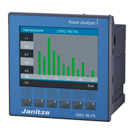
UMG 96-PA 13. 10 Harmonics Harmonics are caused by equipment with • If you are not in the measurement value nonlinear characteristics. These additional display "Overview," switch to this view by frequencies are integer multiples of a funda- repeatedly pressing key 1 (Esc). -
Page 52: Communication In The Bus System
Number of val- none (1 Stopbit) ues Lo none (2 Stopbits) Error Check (CRC) Stopbits (UMG 96-PA): 1 / 2 Stopbits, external: 1 / 2 The "response" of the device may look as Number formats follows: short 16 bit (-2 .. -
Page 53: Digital Inputs/Outputs
Fig. Digital inputs and outputs • You can configure the inputs and outputs via the GridVis® software. • The GridVis® software can be found on the homepage (www.janitza.de) in the download area. Fig. Configuration of the digital inputs via the GridVis ®... - Page 54 UMG 96-PA www.janitza.de Pulse counter All digital inputs can be operated with a Calculation of measurement value: frequency of 25 Hz. Here, the pulse duration and the pulse interval must be greater than Measurement value = Pulse x Pulse value 20 ms.
- Page 55 UMG 96-PA Pulse output ATTENTION! Digital outputs 1 and 2 can be used for the When programming with GridVis®, output of pulses for counting effective energy a selection of energy values that are and apparent energy. For this,a pulse is set at...
- Page 56 UMG 96-PA www.janitza.de Determine pulse value 1. Set the pulse length according to the re- Measurement errors in use quirements of the connected pulse receiv- as pulse output CAUTION! er. For a pulse length of e.g. 30 ms, the device can issue a maximum number of When using the digital outputs as a pulse 60,000 pulses (see Table "Maximum Pulse...
- Page 57 UMG 96-PA Timer output Output for Modbus remote In the device, 64 independent weekly timers Enables switching of the outputs via a Mod- can be set with: bus address. • a resolution of 1 minute. • a freely defined active period within one This function can be configured via the Grid- day.
- Page 58 UMG 96-PA www.janitza.de Output for the comparator group Status Two comparator groups are available to Comparator runtime Logic monitor the thresholds (comparators 1 and 2), each with 3 comparators (A - C). Comparator Threshold The results of the comparators A to C can be Actual value linked using the "AND"...
-
Page 59: Digital
UMG 96-PA Comparator runtime Measurement Comparator runtimes are time counters that create a total for a set comparator output. Threshold I.e. if the condition of the comparator is met and the lead time has expired, the counter increases by the respective amount of time -... -
Page 60: Outputs
UMG 96-PA www.janitza.de 13. 13 Analog output The device has 1 passive analog output, Examples: which can output a maximum current of 0 - 20 mA. Assignment of effective power L1 (output range 4 - 20 mA) An external 24 V DC power adapter is re- quired for operation. -
Page 61: Drag Indicator" Function
UMG 96-PA 13. 14 “Drag indicator” function The “drag indicator” function describes the Capture time: three highest mean value of a measured val- The individually adjustable Capture time de- ues over a defined period of time (time base). scribes a time window in which an incoming pulse triggers a synchronization of the time •... -
Page 62: External Synchronization
UMG 96-PA www.janitza.de 13. 14. 2 External synchronization An external synchronization to calculate the 3 "One pulse" highest mean values can be carried out If the device receives a single pulse or a • via the digital output 3 (e.g. via a pulse... - Page 63 UMG 96-PA "Periodic pulses" • Totaled interim values are set to 0 Different scenarios may result if the device • The time is set to 0 (new relative zero receives periodic pulses via the digital output point) 3 or periodic Modbus commands.
-
Page 64: Synchronization Priority
UMG 96-PA www.janitza.de 13. 14. 3 Synchronization priority An external synchronization is carried out Modbus Function Settings Address range according to various priorities: • Priority 1: Modbus synchronization Set trigger flag for the 0 .. 1 Drag indicator synchronization For this, use the Modbus tool to set the Time base in seconds 60 .. -
Page 65: Recordings
UMG 96-PA 13. 15 Recordings 2 recording profiles are preconfigured in the • Effective current L1 default factory setting of the device. Record- • Effective current L2 ings can be adjusted and extended via the • Effective current L3 GridVis®... -
Page 66: Tariff Switching
UMG 96-PA www.janitza.de 13. 16 Tariff switching Electrical energy values (effective, reactive and apparent energy) can be recorded via internal counters for two tariffs each. Switching between the tariffs (HT/NT) is sup- ported by • Modbus via the • digital input 1 (see Section "Digital Inputs") - Page 67 UMG 96-PA...
-
Page 68: Overview Of Measurement Value Displays
UMG 96-PA www.janitza.de Overview of measurement value displays Main menu (Overview) Network analysis (splash page) Display of voltage L1, L2, L3-N; current L1, L2, L3; power L1, L2, L3 and effective/apparent energy L1-L3 Main menu (Voltage) Voltage L-N Voltage L-L... - Page 69 UMG 96-PA Main menu (Current) Current THD-I Display of current L1, L2, L3 and their minimum Display of distortion factors for the current and maximum values (THD-I) L1, L2, L3 and their minimum and maximum values Curve Display of current curve for L1, L2, L3...
- Page 70 UMG 96-PA www.janitza.de Main menu (Energy) Effective energy Reactive energy Display of total (L1..L3) effective energy (total/ Display of total (L1..L3) reactive energy (total/ drawn/delivered) inductive/capacitive) Apparent energy Tariff Display of total (L1..L3) apparent energy Display of total (L1..L3) effective, reactive and...
- Page 71 UMG 96-PA Main menu (Oscilloscope) Voltage L1 / L2 / L3 Voltage L1..L3 Display of oscillogram for voltage L1, L2 or L3 Display of oscillogram for voltages L1, L2 and Current L1 / L2 / L3 Current L1..L3 Display of oscillogram for current L1, L2 or L3...
- Page 72 UMG 96-PA www.janitza.de Main menu (System) Configuration COMports Overview Submenu Device Configuration Display of received (RX), sent (TX) and faulty Attention: Further information on configuration data packages. Switching current can be found in the Section Operation and analog output Configuration.
- Page 73 UMG 96-PA Submenu (System / Configuration) Language Communication Settings in the device language Settings for the parameters device ad- Attention! Further information on configuration dress, baud rate and data framework can be found in the Section Operation and Configuration.
-
Page 74: Service And Maintenance
UMG 96-PA www.janitza.de Service and maintenance The device underwent various safety checks 15. 5 Device calibration before delivery and is marked with a seal. If a device is open, then the safety checks must The devices are calibrated by the manufac- be repeated. -
Page 75: Battery
UMG 96-PA 15. 8 Battery The internal clock is fed from the supply volt- age. If the supply voltage fails then the clock is powered by the battery. The clock provides date and time information, e.g. for the record- ings and the minimum and maximum values. -
Page 76: Procedure In The Event Of An Error
UMG 96-PA www.janitza.de 15. 9 Procedure in the event of an error Possible error Cause Remedy No display External fuse for the supply voltage was Replace fuse. triggered. No current display. Measurement voltage not Connect measurement voltage. connected. Measurement current not connected. -
Page 77: Technical Data
UMG 96-PA Technical Data General Net weight (with connectors attached) approx. 250 g Packaged weight (incl. accessories) approx. 500g Battery Lithium type CR2032, 3V (approved as per UL 1642) Life cycle of the backlighting 40000h (Backlighting diminishes over this time period to approx. - Page 78 UMG 96-PA www.janitza.de Voltage measurement Three-phase 4-wire systems with rated volatges up to 417 V / 720 V (+-10%) as per IEC 347 V / 600 V (+-10%) as per UL Overvoltage category 600 V CAT III Rated surge voltage...
- Page 79 UMG 96-PA Analog output External supply max. 33 V Current 0 .. 20 mA Update time 1 sec Resolution 10 bit Connectability of the terminals (supply voltage) Connectable conductors. Only connect one conductor per terminal! Single-wire., multiwire, fine-wire 0.08 - 4.0 mm...
-
Page 80: Function Performance Characteristics
UMG 96-PA www.janitza.de 16. 1 Function performance characteristics Function Symbol Precision class Measurement range Display range Total effective power (IEC61557-12) 0 W .. 12.6 kW 0 W .. 999 GW * Total reactive power QA, Qv (IEC61557-12) 0 var .. 16,6 kvar 0 var .. - Page 81 UMG 96-PA...
-
Page 82: Modbus Address List Of Frequently Used Measurement Values
UMG 96-PA www.janitza.de 16. 2 Modbus address list of frequently used measurement values: Address Format RD/WR Variable Unit Comment 19000 float _ULN[0] Voltage L1-N 19002 float _ULN[1] Voltage L2-N 19004 float _ULN[2] Voltage L3-N 19006 float _ULL[0] Voltage L1-L2 19008... -
Page 83: Number Formats
UMG 96-PA 19094 float _IQH[0] varh Reactive energy, inductive, L1 19096 float _IQH[1] varh Reactive energy, inductive, L2 19098 float _IQH[2] varh Reactive energy, inductive, L3 19100 float _IQH_SUML13 varh Reactive energy L1..L3, ind. 19102 float _CQH[0] varh Reactive energy, capacitive, L1... -
Page 84: Dimension Views
UMG 96-PA www.janitza.de 16. 4 Dimension views Battery Fig. Front view Fig. View from below +0,8 87,2 Fig. Side view Fig. Cut-out dimensions... -
Page 85: Connection Example 1
UMG 96-PA 16. 5 Connection example 1 - S1 15 16 Analogue Digital inputs Digital outputs RS485 output UMG 96-PA Supply voltage Voltage measurement Current measurement 11 12 13 PE/FE 230V/400V 50Hz UL/IEC allowed overcurrent circuit breaker UL/IEC allowed overvoltage...