janitza UMG 96-PA User Manual And Technical Data
Power analyzer
Hide thumbs
Also See for UMG 96-PA:
- User manual and technical specifications (98 pages) ,
- User manual and technical data (86 pages) ,
- User manual (85 pages)
Table of Contents
Advertisement
Quick Links
Advertisement
Table of Contents

Related Manuals for janitza UMG 96-PA


Summary of Contents for janitza UMG 96-PA
- Page 1 Power Analyzer UMG 96-PA (from firmware 3.10 / hardware index 1) UMG 96-PA MID+ (from firmware 3.10 / hardware index 1) User manual and technical data Janitza electronics GmbH Vor dem Polstück 6 D-35633 Lahnau Support tel. +49 6441 9642-22 Email: info@janitza.de...
- Page 2 UMG 96-PA / UMG 96-PA-MID + www.janitza.de UMG 96-PA (from firmware 3.10 / hardware index 1) UMG 96-PA (from firmware 3.10 / hardware index 1) MID+ Measurement device for recording energy quantities Doc. no.: 2.061.059.3.a Date: 06/2021 The German version is the original edition of the documentation...
- Page 3 Nonetheless, we wish to point out that updates of this document are not always possible at the same time as technical refinements are implemented in our products. Please see our website under www.janitza.de for the current version. Please see our website under www.janitza.de for the current version.
-
Page 4: Table Of Contents
UMG 96-PA / UMG 96-PA-MID + www.janitza.de TABLE OF CONTENTS 1. Information on the measurement device and the user manual 1. 1 Disclaimer 1. 2 Copyright notice 1. 3 Technical changes 1. 4 About this user manual 1. 5 Defective measurement device/disposal 2. - Page 5 UMG 96-PA / UMG 96-PA-MID + www.janitza.de 7. Installation 7. 1 Nominal voltages 7. 1. 1 Three-phase four-conductor network with grounded neutral conductor 7. 2 Disconnect switch 7. 3 Supply voltage 7. 3. 1 Three-phase three-conductor system 7. 4 Voltage measurement 7.
- Page 6 UMG 96-PA / UMG 96-PA-MID + www.janitza.de 12. 4 Measurement 12. 4. 1 Current and voltage transformers 12. 4. 2 Connection variant 12. 4. 3 Nominal current 12. 4. 4 Nominal frequency 12. 5 Display 12. 5. 1 Brightness 12. 5. 2 Standby after 12.
- Page 7 Intended use 14. 2 Mounting 14. 3 Measuring display for active energy Tamper-proof meter reading cycle of the UMG 96-PA-MID + 14. 4 Changing the battery and setting the time on the MID + certified measurement device 14. 5 14. 6 MID+ certified measurement device - energy recording display 14.
-
Page 8: Information On The Measurement Device And The User Manual
· Make sure that your measurement device match- es the user manual. Our usage information uses the grammatical mascu- · This user manual applies to the UMG 96-PA and line form in a gender-neutral sense! This form always refers equally to women, men and diverse. In order the UMG 96-PA-MID + . -
Page 9: Defective Measurement Device/Disposal
UMG 96-PA / UMG 96-PA-MID + www.janitza.de Defective measurement device/dispos- Before sending defective measurement devices, modules or components back to the manufactur- er for testing: · Contact the manufacturer's Support department. · Send measurement devices, modules or compo- nents complete with all accessories. -
Page 10: Safety
UMG 96-PA / UMG 96-PA-MID + www.janitza.de Safety Product safety The chapter on Safety contains information which must be observed to ensure your personal safety The device reflects current engineering practice and avoid material damage. and accepted safety standards, but hazards can arise nonetheless. - Page 11 · Switch off your installation before commenc- material damage! ing work! Secure it against being switched · Do not use Janitza measurement devices or on! Check to be sure it is de-energized! components for critical switching, control or Ground and short circuit! Cover or block off...
-
Page 12: Warranty In The Event Of Damage
UMG 96-PA / UMG 96-PA-MID + www.janitza.de Electrically qualified personnel Safety information for handling current transformers and measurement devic- To avoid bodily injury and material damage, only es with residual current measurement electrically qualified personnel are permitted to work on the devices and their components, mod-... -
Page 13: Handling Batteries/Accumulators
UMG 96-PA / UMG 96-PA-MID + www.janitza.de Handling batteries/accumulators CAUTION The following apply for the battery used in the Risk of injury or damage to the meter due to device: high measurement currents at the connections of the current transformers! -
Page 14: Product Description
UMG 96-PA / UMG 96-PA-MID + www.janitza.de Product description Device description Incoming goods inspection The device is a multifunctional network analyzer Safe and trouble-free operation of this device and and is suitable for: its components presupposes proper transport, · Measurements and calculations of electrical... -
Page 15: Intended Use
UMG 96-PA / UMG 96-PA-MID + www.janitza.de Intended use Performance characteristics The device is: General · Only for use in the industrial sector. · Front panel installation device with dimensions: · Intended for installation in switchboard cabinets 96 x 96 mm (3.78 x 3.78 in). -
Page 16: Eu Conformity Declaration
· Connect the device and the radio/television 29.01.093 Terminal cover, measurement receiver in different circuits. · If necessary, contact Janitza support or a radio/ 29.01.065 Silicone seal, 96 x 96 television technician. Code of Federal Regulations, Title 47, Part 15, Accessories Subpart B - Unintentional Radiators. -
Page 17: Measuring Method
UMG 96-PA / UMG 96-PA-MID + www.janitza.de 3.12 Operating concept The following apply for the battery used in the device: The operating concept of the measurement device incorporates the following methods: CAUTION · 6 function buttons with display for configura- tion and acquisition of data. -
Page 18: Physical Design Of The Measurement Device
· Open selection menu, activate input, confirm selection (Enter). Description of the function buttons Device type Tab.: Device front panel - display and controls (the front panel of the UMG 96-PA-MID + shown above is similar to the UMG 96-PA) -
Page 19: Rear Of The Device - Connections
UMG 96-PA / UMG 96-PA-MID + www.janitza.de Rear of the device - Connections Fig. Rear view UMG 96-PA/-MID + Item Function/Designation Voltage measurement inputs V 1 to V 3 and V N Supply voltage RS-485 interface Digital inputs Digital outputs... -
Page 20: Rating Plates
Country of origin and manufactur- 11 (21) gin/web address er’s web address CE conformity see section „3.5 EU conformity marking declaration“ on page 16. Table “UMG 96-PA rating plate” 12-21 See table “UMG 96-PA rating plate” Table “UMG 96-PA-MID + rating plates”... - Page 21 UMG 96-PA / UMG 96-PA-MID + www.janitza.de...
-
Page 22: Mounting
The measurement device is suitable for installation in stationary and weather-protected indoor switch- boards. Ground conductive switchboards! ATTENTION Fig. Mounting orientation of the UMG 96-PA/-MID + Material damage due to disregard of the instal- (rear view) lation instructions! Disregard of the installation instructions can damage or destroy your device. -
Page 23: Securing
To Please note the separate information about mount- do so, proceed as follows: ing in the chapter „14. UMG 96-PA-MID+“ on page · Before inserting the device, remove the fastening clips (e.g. with a screwdriver) by levering them horizontally. -
Page 24: Grid Systems
UMG 96-PA / UMG 96-PA-MID + www.janitza.de Grid systems Grid systems and maximum rated voltages ac- cording to DIN EN 61010-1/A1: Three-phase 4-conductor systems with grounded neutral conductor 417 V / 720 V L-L: 347 V / 600 V L-L:... -
Page 25: Installation
IEC death or to material damage! · Do not use the outputs of the Janitza measure- Fig. Nominal network voltages suitable for measuring inputs acc. to EN 60664-1:2003 (valid in three-phase 4-con-... -
Page 26: Disconnect Switch
The option “supply voltage of 24 V” is only valid Install a suitable circuit breaker for the supply volt- for the UMG 96-PA (see chapter “„18. Technical age in the building installation in order to discon- data“ on page 107). - Page 27 (disconnect switch or INFORMATION circuit breaker) The option “supply voltage of 24 V” is only valid for the UMG 96-PA (see chapter “„18. Technical data“ on page 107). INFORMATION The fuse is a line protection, not a device protec- tion! Fig.
-
Page 28: Voltage Measurement
UMG 96-PA / UMG 96-PA-MID + www.janitza.de Voltage measurement There are 3 voltage measurement inputs (V1 to V3) on the rear of the device. 7.4.1 Overvoltage The voltage measurement inputs are suitable for measurement in networks where overvoltages of category 600 V CAT III (rated surge voltage 6 kV) can occur. -
Page 29: Connection Variants For Voltage Measurement
UMG 96-PA / UMG 96-PA-MID + www.janitza.de Fig.: INFORMATION Voltage measurement in a three-phase 3-conductor · The device only determines measured values if a system (asymmetrical voltage L1-N of greater than 20 V (4-conduc- load). tor measurement) or a voltage L1-L2 of greater... -
Page 30: Current Measurement
UMG 96-PA / UMG 96-PA-MID + www.janitza.de Connection variant “Voltage measurement with Current measurement functional earthing (FE)” The device: · Is designed for the connection of current transform- For a measurement in a grounded 3-phase sys- ers with secondary currents of ../1 A and ../5 A. -
Page 31: Current Direction
UMG 96-PA / UMG 96-PA-MID + www.janitza.de 7.5.1 Current direction WARNING You can correct the current direction for each Risk of injury due to electrical voltage at current phase individually via the serial interfaces pro- transformers! vided. This means that in the case of incorrect... -
Page 32: Connection Variants For Current Measurement
UMG 96-PA / UMG 96-PA-MID + www.janitza.de 7.5.4 Connection variants for current measurement Fig.: Fig.: Current measurement Current measurement via current transformer via current transformer in a three-phase 4-con- in a three-phase 3-con- ductor system ductor system Load Load Fig.: Fig.:... - Page 33 UMG 96-PA / UMG 96-PA-MID + www.janitza.de...
-
Page 34: Connection And Pc Connections
Ethernet interface can be found in the usage information on the module. PC with GridVis ® UMG 96-PA / MID+ RS-485 RS-485 2. Use of the UMG 96-PA/-MID+ (server device) via a UMG with gateway functionality (e.g. UMG 512 client device): PC with GridVis ® Ethernet Ethernet... -
Page 35: Interface
UMG 96-PA / UMG 96-PA-MID + www.janitza.de RS-485 interface Shielding The device communicates with the Modbus RTU Provide a twisted and shielded cable for connec- protocol via an RS-485 interface (3-pole plug tions via the interfaces and observe the following contact). -
Page 36: Termination Resistors
UMG 96-PA / UMG 96-PA-MID + www.janitza.de Termination resistors Bus structure At the beginning and end of a segment, the cable In a bus structure: is to be terminated with resistors (120 Ω, 1/4 W). · Connect all devices in line. - Page 37 Server device Power supply necessary Client device - e.g. UMG 604-PRO Server device - UMG 96-PA / -MID + Bus terminator on In a Modbus system the Modbus organization (modbus.org) uses the terms “client” and “server” to de- scribe Modbus communication, characterized by communication between client devices - formerly mas- ter devices - that initiate communication and make requests, and server devices - formerly slave devices - that process the requests and return an appropriate response (or error message).
-
Page 38: Digital Inputs And Outputs
UMG 96-PA / UMG 96-PA-MID + www.janitza.de Digital inputs and outputs The measurement device has: External auxiliary voltage 24 VDC · 3 digital inputs and · 3 digital outputs UMG 96-PA Digital inputs Digital inputs 1-3 The measurement device has three digital inputs... -
Page 39: Digital Outputs
UMG 96-PA / UMG 96-PA-MID + www.janitza.de Digital outputs External auxiliary voltage 24 VDC The measurement device has 3 digital outputs, which: · Are electrically isolated from the evaluation elec- tronics via optocouplers. · Have a common reference. UMG 96-PA ·... -
Page 40: Analog Outputs
UMG 96-PA / UMG 96-PA-MID + www.janitza.de 10. Analog outputs 11. Operation The measurement device has 1 passive analog The measurement device is operated using 6 func- output which can deliver a current of 0 - 20 mA. An tion buttons which have different functions: external power supply unit (24 V DC) is required for operation. -
Page 41: Measuring Display "Overview
After restoration of network power, the UMG 96- device: PA starts with the measuring display Overview. UMG 96-PA-MID + start screen: The UMG 96-PA-MID + starts with the measuring display MID active energy. The Overview measuring display contains the measurement device name and an overview of important measured values. -
Page 42: Overview Of Menu Displays
Apparent power (3P4W network only) Active power history Reactive power history Apparent power history Oscilloscope Energy Voltage Active energy (start screen UMG 96-PA-MID + ) Reactive energy Apparent energy Tariff L1-3 Energy recording (only UMG 96-PA-MID + ) Current Consumption overview... -
Page 43: Configuring A New Start Screen
(default setting). German English INFORMATION Communication/Fieldbus Device address · Ex works, the UMG 96-PA has the Pass- word00000 (no password). Please refer to Baud rate section „Password“ on page 52. Data frame · The measurement device locks the device con- figuration for 10 min. -
Page 44: Configuration
12.2 Language INFORMATION Use the Language item of the Configuration The configuration of the UMG 96-PA-MID + is pro- window to configure the language for the device's tected by a password (see „14.9 Password config- user interface: uration“ on page 91). -
Page 45: Communication
UMG 96-PA / UMG 96-PA-MID + www.janitza.de 12.3 Communication Settings Use the Communication item of the Configuration · Device address: window to configure parameters for the RS-485 Select a device address for the device with which interface of your device. -
Page 46: Measurement
UMG 96-PA / UMG 96-PA-MID + www.janitza.de 12.4 Measurement · The Measurement window appears with the settings for the current and voltage transformers In the “Measurement“ menu, configure the ratio (primary and secondary). of the current and voltage transformers (primary to secondary side), the connection variants, the nominal current and the nominal frequency. -
Page 47: Connection Variant
UMG 96-PA / UMG 96-PA-MID + www.janitza.de Connection variant 4w3m INFORMATION The UMG 96-PA-MID + has an integrated logbook. The logbook: · Appears only in the MID device (see „14.8 Log- book“ on page 91). · Records password changes, changes in cur-... -
Page 48: Nominal Current
S1 S2 S1 S2 S1 S2 S1 S2 S1 S2 S1 S2 3w 2i 3w 2m UMG 96-PA / UMG 96-PA-MID + www.janitza.de 12.4.3 Nominal current For a defined operation of the device, you need the nominal current in addition to the settings of the current and voltage transformer ratios. -
Page 49: Nominal Frequency
· Select your frequency range with buttons 3 () and 4 (). INFORMATION The UMG 96-PA-MID + supports automatic fre- quency determination only (45-65 Hz)! · Confirm your entries with button 6 (Enter) or end the action by pressing button 1 (Esc). -
Page 50: Display
UMG 96-PA / UMG 96-PA-MID + www.janitza.de 12.5 Display · Confirm your entries with button 6 (Enter) or end the action by pressing button 1 (Esc). Use the item Display of the measurement device to · To return to the start screen, press button 1 twice configure the following display settings: (Esc) and then press button 2 (Home). -
Page 51: Colors
UMG 96-PA / UMG 96-PA-MID + www.janitza.de 12.5.4 Colors 12.6 System Colors for the display of current and voltage in the In the System window, the user of the measure- graphical visualizations. ment device can: · View device-specific system settings. -
Page 52: Firmware/Serial Number
00000 = without password the action by pressing button 1 (Esc). · To return to the start screen, press button 1 twice The UMG 96-PA is delivered ex works with the (Esc) and then press button 2 (Home). password 00000 (no password) configured. -
Page 53: Reset
Min./Max. values and records! INFORMATION When resetting the UMG 96-PA-MID/MID + , the · Open the Configuration window as previously certified energy values for active energy, delivered described. and applied cannot be deleted! ·... - Page 54 This function resets all settings, such as configura- tions and recorded data, to the factory settings. INFORMATION INFORMATION The UMG 96-PA-MID + cannot be restarted via the display! The settings for the current and voltage transform- ers of the UMG 96-PA-MID + cannot be reset! ·...
-
Page 55: Modbus Editor
UMG 96-PA / UMG 96-PA-MID + www.janitza.de 12.7 Modbus editor INFORMATION The function Modbus Editor is used to configure Further information on the analog outputs can be various functions or to read out measured val- found in chapter “„10. Analog outputs“ on page ues directly on the measurement device, without 40 and in section “„13.15 Configuration of the... - Page 56 UMG 96-PA / UMG 96-PA-MID + www.janitza.de You can access the Modbus editor as follows: Example for the measured value Active power: · Open the Configuration window as previously described. · In the Configuration window, select the item · Use buttons 3 () and 4 () to select the item Modbus editor and confirm with button 6 (Enter).
-
Page 57: Network System Configuration Via The Modbus Editor
UMG 96-PA / UMG 96-PA-MID + www.janitza.de 12.7.1 Network system configuration via the · Use buttons 3 () and 4 () to select the item Modbus editor value and confirm with button 6 (Enter). · The selected item is shown “yellow”. - Page 58 UMG 96-PA / UMG 96-PA-MID + www.janitza.de INFORMATION As an option to network system configuration on the measurement device (Modbus address 117), you can configure the network systems in the GridVis ® software. To do so, use one of the 3 types of mea-...
- Page 59 UMG 96-PA / UMG 96-PA-MID + www.janitza.de...
-
Page 60: Commissioning
UMG 96-PA / UMG 96-PA-MID + www.janitza.de 13. Commissioning 13.1 Applying the supply voltage WARNING 1. Connect the supply voltage via the terminal on Risk of injury due to electrical voltage! the back of the measurement device. If the device is exposed to surge voltages above 2. -
Page 61: Frequency
· Open the menu with button 1 (Menu). by the device. INFORMATION The UMG 96-PA-MID + supports automatic frequen- cy determination only (45-65 Hz)! · To determine the mains frequency, the mea- surement device requires a voltage greater than... -
Page 62: Fundamentals On The Phasor Diagram
UMG 96-PA / UMG 96-PA-MID + www.janitza.de 13.5.1 Fundamentals on the phasor diagram Representation of capacitance: The phasor diagram graphically describes the · The current is ahead of the voltage. phase shift or phase angle between the voltage · The phase shift of an “ideal capacitor” is 90°. -
Page 63: Checking Of Voltage And Current Inputs By Means Of Phasor Diagram
UMG 96-PA / UMG 96-PA-MID + www.janitza.de 13.6 Checking of voltage and current inputs 13.7 Overrange by means of phasor diagram If the measuring range is exceeded, a warning The phasor diagram can be used to check incor- appears in the device display, e.g. for the voltage, rect connections at the voltage and current inputs. -
Page 64: Control Of The Power Measurement
UMG 96-PA / UMG 96-PA-MID + www.janitza.de 13.9 Control of the power measurement 13.10 Control of the communication Short-circuit all current transformer outputs except The measurement device counts all received (RX), one and check the indicated powers. all sent (TX) and all faulty data packets. - Page 65 UMG 96-PA / UMG 96-PA-MID + www.janitza.de Now check the RS-485 communication parame- ters, such as: · All received (RX), all sent (TX) and all faulty data packets. Ideally, the number of errors in the col- umn Error will equal “0”.
-
Page 66: Delete Min./Max. Values
UMG 96-PA / UMG 96-PA-MID + www.janitza.de 13.11 Delete min./max. values · The submenu for Voltage appears. · In the submenu, select the item Voltage L-N with In the measuring displays for voltage, current and buttons 3 () and 4 () and confirm with button power, the device offers the function of deleting 6 (Enter). - Page 67 UMG 96-PA / UMG 96-PA-MID + www.janitza.de...
-
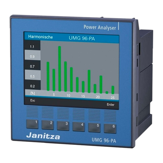
Page 68: Harmonics Current (Harmonics)
45 - 65 Hz. The calculated harmonics of the voltages and currents refer to this fundamental oscillation. The UMG 96-PA and UMG 96-PA-MID + calcu- late harmonics of up to 40 times the fundamental oscillation. -
Page 69: Communication In The Bus System
The “response” of the device can then look as none (1 stop bit) follows: none (2 stop bits) Designation Hex Comment Stop bits (UMG 96-PA): 1 / 2 External stop bits: 1 / 2 Device address Address=1 Function Number formats... -
Page 70: Digital Inputs/Outputs
INFORMATION · Digital input 1: Configuration as tariff switching (HT/LT). The UMG 96-PA-MID + offers only limited configura- · Digital input 2: tion options for the digital outputs! Configuration for a synchronization of the mea- surement device clock with selection of minute or hour synchronization (synchronization of the 13.14.1 Digital inputs... - Page 71 UMG 96-PA / UMG 96-PA-MID + www.janitza.de Pulse counter Measured value calculation: All digital inputs can be operated with a frequency of 25 Hz. The pulse duration (pulse width) and the Measured value = pulse x pulse valency pulse pause must be greater than 20 ms.
-
Page 72: Digital Outputs
· Pulse valency · Digital output 1 INFORMATION - Pulse output for active energy The pulse duration of the UMG 96-PA-MID + is - Output for timer switch 30 ms and is not configurable. - Modbus remote output · Digital output 2... - Page 73 UMG 96-PA / UMG 96-PA-MID + www.janitza.de 3. Calculate pulse valency: The weekly timers are configured using the Grid- software in the “Timer” configuration area. ® Max. connected load [Pulses/Wh] Pulse valency = Max. number of pulses/h Pulse valency = 135 kW / 60000 pulses/h Pulse valency = 0.00225 pulses/kWh...
- Page 74 UMG 96-PA / UMG 96-PA-MID + www.janitza.de Output for comparator group Two comparator groups (comparator 1 and 2) each with 3 comparators (A - C) are available for monitoring limit values. The results of comparators A to C can be linked with “AND”...
- Page 75 UMG 96-PA / UMG 96-PA-MID + www.janitza.de Comparator running time Comparator running times are time counters that Measured value add up continuously for a set comparator output. This means that if the condition of the comparator Limit value is fulfilled and the lead time has expired, the count-...
-
Page 76: Configuration Of The Analog Output
UMG 96-PA / UMG 96-PA-MID + www.janitza.de 13.15 Configuration of the analog output Examples: Allocation of active power L1 The measurement device has an analog output (output range 4 - 20 mA) that can output a maximum current of 20 mA. -
Page 77: Drag Indicator" Function
UMG 96-PA / UMG 96-PA-MID + www.janitza.de 13.16 “Drag indicator” function Capture time: The individually configurable Capture time de- The “Drag indicator” function describes the 3 scribes a time window in which an incoming highest average values of value types over a pulse synchronizes the point in time. -
Page 78: External Synchronization
UMG 96-PA / UMG 96-PA-MID + www.janitza.de 13.16.2 External synchronization “One pulse” If the device receives a pulse or a Modbus com- An external synchronization for the calculation of mand once outside the capture time, the mea- the 3 highest average values is performed: sured values added up to that point are reset for ·... - Page 79 UMG 96-PA / UMG 96-PA-MID + www.janitza.de “Periodic pulses” Scenario “Pulse before time base, within the capture time”: If the device receives periodic pulses via digital input 3 or periodic Modbus commands, there are · Perform value calculation now. different scenarios.
-
Page 80: Synchronization Priority
UMG 96-PA / UMG 96-PA-MID + www.janitza.de 13.16.3 Synchronization priority Configura- Modbus Function tion address An external synchronization takes place according range to different priorities: Set trigger flag for 0 .. 1 drag indicator synchronization · Priority 1: Time base in seconds 60 .. -
Page 81: Drag Indicator - Measurement Device Displays
UMG 96-PA / UMG 96-PA-MID + www.janitza.de 13.16.4 Drag indicator - Measurement device displays As already described in section “13.16 Drag indi- cator function”, the drag indicator function shows the 3 highest average values of value types over a defined period (time base). -
Page 82: Delete Drag Indicator
UMG 96-PA / UMG 96-PA-MID + www.janitza.de 13.16.5 Delete drag indicator In each drag indicator display of the measurement device - current, active and apparent power - a dialog box for deleting the drag indicator values appears when button 6 is pressed: Fig. -
Page 83: Recordings
UMG 96-PA / UMG 96-PA-MID + www.janitza.de 13.17 Recordings Recording 1 The following measured values are recorded with a Two recording profiles are preconfigured in the time base of 15 minutes: factory default setting of the device. Adaptation and expansion of recordings can be done using ·... -
Page 84: Tariff Switching
UMG 96-PA / UMG 96-PA-MID + www.janitza.de 13.18 Tariff switching INFORMATION The recording of electrical energy values (active, Configure tariff switching using the GridVis ® reactive and apparent energy) is done via internal software! meters for two tariffs each. Switching between the tariffs (HT/LT) is supported ·... -
Page 85: Alarms For "Low Battery Voltage" And "Set Time
UMG 96-PA / UMG 96-PA-MID + www.janitza.de 13.19 Alarms for “Low battery voltage” and After a battery replacement, an alarm appears on “Set time” the measurement device display stating “Please set time”. INFORMATION The measurement device · Sets the time to the factory setting when... -
Page 86: Umg 96-Pa-Mid
Fig. Front panel of the UMG 96-PA-MID + 14.1 Intended use The UMG 96-PA-MID + is to be used in accor- Fig. Installation of the terminal covers on the measurement dance with national specifications. The period of device validity of the calibration depends on the applica- ble national law. -
Page 87: Measuring Display For Active Energy
GridVis software. ® INFORMATION The energy recording function of the UMG 96-PA- MID+ is tamper-proof, certified and · meets the requirements of PTB-A 50.7 (Physika- lische Technische Bundesanstalt); · synchronizes with an NTP server according to the UTC time scale (only devices with Ethernet module!);... -
Page 88: Changing The Battery And Setting The Time On The Mid + Certified Measurement Device
UMG 96-PA / UMG 96-PA-MID + www.janitza.de 14.5 Changing the battery and setting the After a battery replacement, an alarm appears on time on the MID + certified measure- the measurement device display stating “Please ment device set time”. INFORMATION The MID + certified measurement device ·... -
Page 89: Mid+ Certified Measurement Device - Energy Recording Display
(date) set by the user after a period of 90 seconds. This allows the user to After setting the time on the UMG 96-PA-MID + , correct incorrect entries within the 90 s. Otherwise, you can access the energy recording display of the the device adopts the time (date) immediately. -
Page 90: Load Profile
UMG 96-PA / UMG 96-PA-MID + www.janitza.de Meaning of the symbols in the meter reading cycle display of the device: Status Description Valid data record Manual time change made Time asynchronous / not set in the last 3 days Fig. Example “Meter reading cycle” window with differ-... -
Page 91: Logbook
UMG 96-PA / UMG 96-PA-MID + www.janitza.de 14.8 Logbook · If the password is entered incorrectly 5 times, the device locks the configuration for 10 minutes. The logbook · Records password changes, changes in cur- Setting range: 00001 - 99999... -
Page 92: Measurement Device Acceptance Report
UMG 96-PA / UMG 96-PA-MID + www.janitza.de 14.11 Measurement device acceptance re- port When installing and working on MID+ certified measurement devices, the person working on the measurement device must ensure that a measure- ment device acceptance report is prepared or, if... -
Page 93: Time Synchronization
First connect a time pulse to digital input 2, e.g. the pulse from the electric utility or a GPS timer (GPS radio receiver for receiving and processing the GPS time signal; available as Janitza accesso- ry). 14.12.2 Ethernet interface - measurement... -
Page 94: Overview Of Measuring Displays
UMG 96-PA / UMG 96-PA-MID + www.janitza.de 15. Overview of measuring displays Menu (Overview) Network analysis (Start screen) Three-phase 4-conductor system Display of Three-phase 3-conductor system Display of · Voltage L1-N, L2-N, L3-N, frequency; · Voltage L1-L2, L2-L3, L3-L1, frequency;... - Page 95 UMG 96-PA / UMG 96-PA-MID + www.janitza.de Menu (Current) Current THD-I Display of distortion factors for the current Display of current L1, L2, L3 and their min. / max. values (THD-I) L1, L2, L3 and their min. / max. values...
- Page 96 UMG 96-PA / UMG 96-PA-MID + www.janitza.de Menu (Energy) Active, reactive, apparent energy Tariff Displays sum (L1..L3) of active, reactive and Displays the sum (L1..L3) of active, reactive and apparent energy apparent energy according to tariffs MID active energy (start screen), Tariff - not MID compliant UMG 96-PA-MID+ (Energy &...
- Page 97 UMG 96-PA / UMG 96-PA-MID + www.janitza.de Menu (drag indicator) Voltage L1, L2, L3 Current Drag indicator display of the currents L1, L2 and L3 with the 3 maximum values and a time stamp. Active power (Appl. and Del.) L1, L2, L3 Active power sum (Appl.
- Page 98 UMG 96-PA / UMG 96-PA-MID + www.janitza.de Menu (Harmonics) Voltage L1 / L2 / L3 Voltage L1 / L2 / L3 Display of the harmonics up to the 40th harmonic Display of the harmonics up to the 40th harmon- (voltage L1, L2, L3)
- Page 99 UMG 96-PA / UMG 96-PA-MID + www.janitza.de Menu (System Info) Submenu System Info Com. RS-485 Peripherals Display of received (RX), transmitted (TX) and Display of the states of the digital inputs and faulty data packets, RS-485 mode, device outputs, value of the analog output.
-
Page 100: Configuration Display, Mid + Certified Measurement Device
UMG 96-PA / UMG 96-PA-MID + www.janitza.de Configuration display, MID + certified measurement device 15.1 Menu (Configuration) UMG 96-PA-MID + : Configuration of the pass- word, display of the firmware version and the software ID NOTE The configuration of the UMG 96-PA-MID + is locked with a password (default setting 10000). - Page 101 UMG 96-PA / UMG 96-PA-MID + www.janitza.de...
-
Page 102: Configuration Display For Umg 96-Pa
UMG 96-PA / UMG 96-PA-MID + www.janitza.de 15.2 Configuration display for UMG 96-PA Menu (Configuration) For information on the items in the Configura- tion window, see chapter “„12. Configuration“ on page 44. Language Setting the language to German. Setting the language to English. - Page 103 UMG 96-PA / UMG 96-PA-MID + www.janitza.de Display Settings for brightness, standby time after, bright- Settings for the display colors of voltage and ness (standby) and the display colors for voltage current (L1, L2, L3). and current (L1, L2, L3).
-
Page 104: Service And Maintenance
UMG 96-PA / UMG 96-PA-MID + www.janitza.de 16. Service and maintenance 16.3 Service Prior to outbound delivery, the device is subjected to various safety tests and is marked with a seal. For questions not answered or described in this If a device is opened, the safety tests must be re- manual, please contact the manufacturer. -
Page 105: Clock/Battery
UMG 96-PA / UMG 96-PA-MID + www.janitza.de 16.6 Clock/Battery The supply voltage supplies the internal clock of the meter. If the supply voltage fails, the battery takes over the supply of voltage to the clock. The clock provides date and time information, for ex- ample for recordings and min. -
Page 106: Procedure In The Event Of A Malfunction
UMG 96-PA / UMG 96-PA-MID + www.janitza.de 17. Procedure in the event of a malfunction Failure mode Cause Remedy No display External fuse for the supply voltage has Replace fuse. tripped. No current display. No measured voltage connected. Connect measured voltage. -
Page 107: Technical Data
(UL approval) Option 24 V *: 1 - 6 A (Char. B) The 24 V option only applies to the UMG 96-PA! Recommendation for the maximum number of devices on a line circuit breaker: Option 230 V: Line circuit breaker B6A: max. 4 devices / line circuit breaker B16A: max. 11 devices... - Page 108 200 ms Pulse output max. 50 Hz (energy pulses) Digital output 1 (terminal 21/22) of the UMG 96-PA-MID + provides the active energy (applied/delivered) measured value! Digital inputs 3 digital inputs, solid state relays, not short-circuit proof. Maximum counter frequency...
- Page 109 UMG 96-PA / UMG 96-PA-MID + www.janitza.de Cable length (digital inputs/outputs) Up to 30 m (32.81 yd) Unshielded Greater than 30 m (32.81 yd) Shielded Analog outputs External power supply max. 33 V Current 0 .. 20 mA Update time Load max.
- Page 110 Suitable grid systems 1p2w, 3p3w, 3p4w 1) The following applies for the UMG 96-PA-MID+ when measuring voltage using voltage transformers: Use calibrated/permissi- ble voltage transformers for MID-compliant measurement (secondary: 3 x 57.7/100 V - 3 x 289/500 V). 2) The pulse valency S0 is automatically adapted to the voltage transformer ratio that has been set. The momentary pulse va-...
-
Page 111: Performance Characteristics Of Functions
UMG 96-PA / UMG 96-PA-MID + www.janitza.de 18.1 Performance characteristics of functions Function Symbol Accuracy class Measuring range Display range Total active power (IEC61557-12) 0 W .. 12.6 kW 0 W .. 999 GW * Total reactive power QA, Qv 1 (IEC61557-12) 0 var .. -
Page 112: Modbus Addresses Of Frequently Used Measured Values
UMG 96-PA / UMG 96-PA-MID + www.janitza.de 18.2 Modbus addresses of frequently used measured values Address Format RD/WR Variable Unit Comment 19000 float _ULN[0] Voltage L1-N 19002 float _ULN[1] Voltage L2-N 19004 float _ULN[2] Voltage L3-N 19006 float _ULL[0] Voltage L1-L2... -
Page 113: Number Formats
UMG 96-PA / UMG 96-PA-MID + www.janitza.de Address Format RD/WR Variable Unit Comment 19096 float _IQH[1] varh Reactive energy, inductive, L2 19098 float _IQH[2] varh Reactive energy, inductive, L3 19100 float _IQH_SUML13 varh Reactive energy L1..L3, ind. 19102 float _CQH[0]... -
Page 114: Dimensional Drawings
UMG 96-PA / UMG 96-PA-MID + www.janitza.de 18.5 Dimensional drawings · The figures are for illustration purposes only and are not to scale. 96 mm 3.78 in Battery 96 mm 3.78 in Fig. Front view 1) Bottom view +0,8 3.62 +0.03... - Page 115 UMG 96-PA / UMG 96-PA-MID + www.janitza.de 18.6 Connection example 1 - S1 Data GND 15 16 Analog Digital inputs Digital outputs RS485 output UMG 96-PA Supply voltage Voltage measurement Current measurement 11 12 13 PE/FE 230V/400V 50Hz 1) UL/IEC approved overcurrent protective device...
- Page 116 Tel.: +49 6441 - 9642-0 Fax: +49 6441 - 9642-30 Email: info@janitza.de info@janitza.de | www.janitza.com Doc. no. 2.061.059.3.a | Date 06/2021 | Subject to technical changes. The latest version of the document can be found in the download area at www.janitza.de.