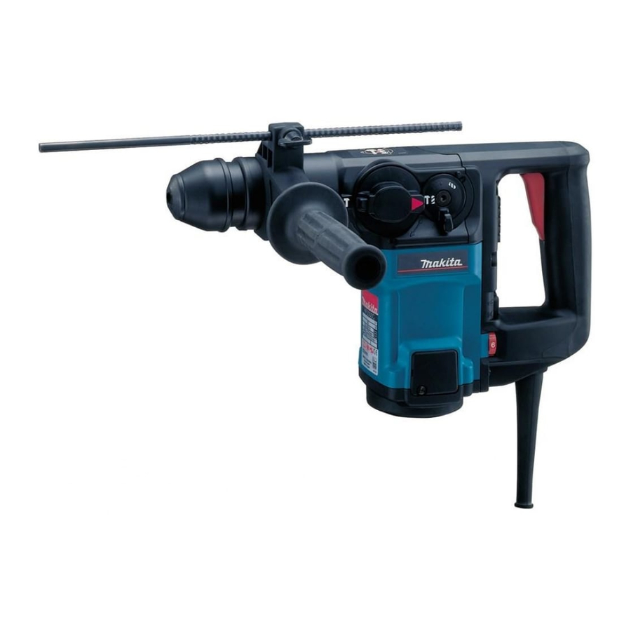
Makita HR3000C Instruction Manual
30 mm (1 - 3/16”)
Hide thumbs
Also See for HR3000C:
- Instruction manual (60 pages) ,
- Parts breakdown (4 pages) ,
- Instruction manual (20 pages)
Table of Contents
Advertisement
Advertisement
Table of Contents

Related Manuals for Makita HR3000C


Summary of Contents for Makita HR3000C
- Page 1 Rotary Hammer 30 mm (1 - 3/16”) MODEL HR3000C I N S T R U C T I O N WARNING: For your personal safety, READ and UNDERSTAND before using. SAVE THESE INSTRUCTIONS FOR FUTURE REFERENCE. w w w . m a k i t a t o o l s . c o m...
-
Page 2: Specifications
(one blade is wider than the other.) This plug will fit in a polarized outlet only one way. If the plug does not fit fully in the outlet, reverse the plug. If it HR3000C 30 mm (1-3/16”) 90 mm (3-1/2”) 13 mm (1/2”) 30 mm (1-3/16”) - Page 3 still does not fit, contact a qualified elec- trician to install a polarized outlet. Do not change the plug in any way. Double insula- tion eliminates the need for the three wire grounded power cord and grounded power supply system. 5.
-
Page 4: Specific Safety Rules
Not More Than SPECIFIC SAFETY RULES DO NOT let comfort or familiarity with product (gained from repeated use) replace strict adherence to rotary hammer safety rules. If you use this tool unsafely or incorrectly, you can suffer serious personal injury. - Page 5 4. Be sure the bit is secured in place before operation. 5. Under normal operation, the tool is designed produce screws can come loose easily, causing a breakdown or accident. Check tightness of screws carefully before operation. 6. In cold weather or when the tool has not been used for a long time, let the tool warm up for a while by operating it under no load.
-
Page 6: Functional Description
FUNCTIONAL DESCRIPTION 003110 1. Switch trigger 003118 1. Adjusting dial CAUTION: • Always be sure that the tool is switched off and unplugged before adjusting or checking function on the tool. Switch action CAUTION: • Before plugging in the tool, always check to see that the switch trigger actuates properly and returns to the “OFF”... - Page 7 003126 1. Change lever 2. Shift lever 3. Lock button 4. “Rotation with hammering” symbol 003129 1. Pointer 2. “Rotation with hammering” symbol 003132 1. Pointer 2. “Rotation only” symbol 003134 1. Pointer 2. “Hammering only” symbol Selecting the action mode When selecting an action mode, first set the change lever and the shift lever to the position shown in the figure.
-
Page 8: Torque Limiter
003136 1. Hammering only 2. Rotation only 3. Rotation with hammering 003137 1. Power-ON indicator lamp (green) 2. Service indicator lamp (red) CAUTION: • Do not rotate the change lever and/or shift lever when the tool is running under load. The tool will be damaged. •... - Page 9 ASSEMBLY 003145 1. Side grip 003150 1. Bit shank 2. Bit grease 003160 1. Bit 2. Chuck cover CAUTION: • Always be sure that the tool is switched off and unplugged before carrying out any work on the tool. Side grip (auxiliary handle) CAUTION: •...
-
Page 10: Depth Gauge
003167 1. Bit 2. Chuck cover 003171 1. Lock button 2. “O” symbol 003175 003182 1. Depth gauge 2. Clamp screw 3. Grip base To remove the bit, pull the chuck cover down all the way and pull the bit out. Bit angle (when chipping, scaling or demolishing) The bit can be secured at 12 different angles. -
Page 11: Operation
003186 1. Dust cup OPERATION 003198 002449 1. Blow-out bulb Dust cup (optional accessory) Use the dust cup to prevent dust from falling over the tool and on yourself when performing overhead drilling opera- tions. Attach the dust cup to the bit as shown in the figure. The size of bits which the dust cup can be attached to is as follows. -
Page 12: Maintenance
003204 003221 1. Drill chuck assembly MAINTENANCE Chipping/Scaling/Demolition Set the change lever and the shift lever to the Hold the tool firmly with both hands. Turn the tool on and apply slight pressure on the tool so that the tool will not bounce around, uncontrolled. -
Page 13: Replacing Carbon Brushes
001146 1. Commutator 2. Insulating tip 3. Carbon brush 003224 1. Screwdriver 2. Brush holder cover 003230 1. Screwdriver 2. Brush holder cap Replacing carbon brushes When the resin insulating tip inside the carbon brush is exposed to contact the commutator, it will automatically shut off the motor. - Page 14 Wipe out the old grease inside and replace with a fresh grease (30 g; 1 oz). Use only Makita genuine hammer grease (optional accessory). Filling with more than the spec- ified amount of grease (approx. 30 g; 1 oz) can cause faulty hammering action or tool failure.
- Page 15 CAUTION: • These accessories or attachments are recommended for use with your Makita tool specified in this manual. The use of any other accessories or attachments might present a risk of injury to persons. Only use accessory or attachment for its stated purpose.
- Page 16 Memo...
- Page 17 First-Class Postage Required Post Office will not deliver without proper postage. Makita U.S.A., Inc. 14930 Northam Street La Mirada, CA 90638-5753 Fold...
- Page 18 Paste 3. How did you learn about this product: Magazine From Dealer Newspaper Store Display Catalog 4. Most favored points are: Design Features Size Price Makita Brand MODEL NO. YEAR SERIAL NO. PHONE 20-29 30-39 40-49 Paste Paste Radio Exhibition...
-
Page 19: Factory Service Centers
Date Purchased When you need service: Send complete tool (prepaid) to one Dealer’s Name & Address of the Makita Factory Service Centers listed, or to an Authorized Makita Service Center. Be sure to attach a letter to the outside of Model No. - Page 20 MAKITA LIMITED ONE YEAR WARRANTY Warranty Policy Every Makita tool is thoroughly inspected and tested before leaving the factory. It is warranted to be free of defects from workmanship and materials for the period of ONE YEAR from the date of original purchase.