Bosch Solution 2000 Quick Start Manual
Hide thumbs
Also See for Solution 2000:
- Installation manual (150 pages) ,
- User manual (31 pages) ,
- Programming (12 pages)
Advertisement
Quick Links
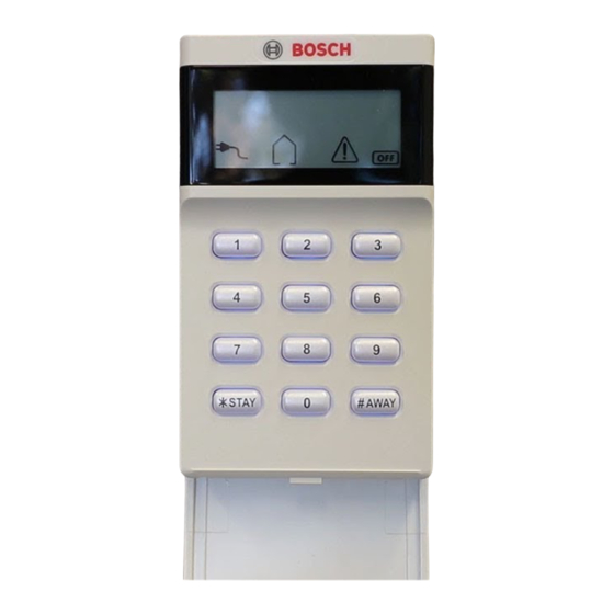
Codepads on Solution 2000/3000
Codepads
The Solution 2000/3000 control panels support two types of codepads: an Alphanumeric LCD
codepad (IUI-SOL-TEXT) and an Icon LCD codepad (IUI-SOL-ICON).
If multiple codepads reside on the same system, each codepad must have a unique address. The
Solution 2000/3000 control panels support up to 4 codepads, addresses 01-04. DIP switch address
settings greater than 4 prevent the codepad from processing messages recieved on the SDI2 bus and
the option bus. Any change to the DIP switch requires a power cycle or software reboot of the module
for the new external address to be read.
DIP Switch
Codepad
Address
1
On
2
Off
3
On
4
Off
Table 4.1 Codepad DIP Switch address settings
1
2
Off
Off
On
Off
On
Off
Off
On
Installation
Set the address switches for the proper
address, mount the mounting plate, wire
to the control panel, attach the codepad to
the mounting plate.
NOTICE!
Do not remove the spring from the tamper
switch on the IUI-SOL-ICON. Removing
the spring will cause a Codepad Tamper
Trouble and a report will be sent if
configured to do so.
Set the address
The IUI-SOL-TEXT and IUI-SOL-ICON
have 6 DIP switches that support SDI2
addresses 01 to 16. DIP switches
determine the address for the codepad.
The control panel uses address for
communications. Use a ballpoint pen to set
DIP Switch Number
3
4
Off
Off
Off
Off
Off
Off
Off
Off
5
6
On
On
On
On
Advertisement

Related Manuals for Bosch Solution 2000


Summary of Contents for Bosch Solution 2000
- Page 1 If multiple codepads reside on the same system, each codepad must have a unique address. The Solution 2000/3000 control panels support up to 4 codepads, addresses 01-04. DIP switch address settings greater than 4 prevent the codepad from processing messages recieved on the SDI2 bus and the option bus.
- Page 2 Install the Module 1. Use the provided anchors and screws to mount the codepad base on the wall. 2. Pull the necessary wiring through the mounting plate Wire to the control panel Wire the codepad to the control panel using the control panel terminals labeled R, Y, G, B (PWR, A, B, COM).
- Page 4 The panel also supports using a Touchscreen TS-5 this is a 5 inch This touchscreen can only be mounted HORIZONTALLY and it is addressed under Settings. These have a higher current draw (400mA nominal / 800mA peak) than the SOL-TEXT or SOL-ICON TS-7 this is a 7 inch codepads (105mA) and the SDI-2-Bus is rated to The TS-7 Touchscreen can be...