Table of Contents
Advertisement
Quick Links
DACT-E3
Digital Alarm Communicator Transmitter
Product Installation Document
CAUTION 1: STATIC SENSITIVE EQUIPMENT:
!
THIS EQUIPMENT IS SENSITIVE TO STATIC ELECTRICITY. IT MAY BE DAMAGED IF NOT PROPERLY HANDLED.
TRANSPORT AND STORE THIS UNIT IN A STATIC-SHIELDING BAG.
FAILURE TO OBSERVE THIS REQUIREMENT COULD CAUSE LATENT DAMAGE TO THE EQUIPMENT WHICH
MIGHT NOT MANIFEST ITSELF UNTIL AFTER THE EQUIPMENT IS PLACED IN SERVICE.
CAUTION 2: DISCONNECT ALL POWER:
!
REMOVE ALL SOURCES OF POWER BEFORE SERVICING, REMOVING OR INSTALLING ANY UNITS.
Section 1: Description
The DACT-E3 (Digital Alarm Communicator Transmitter) sub-assembly is a digital communications circuit. It transmits and
verifies digital signals over the telephone network to a Central Station. The DACT-E3 is compatible with the following digital
signaling formats, and complies with FCC Part 8, Telecommunications Standards for DC and AC Ringer.
•
SIA DC8
•
SIA DCS20
It is used as the communications circuit with the following modules and systems.
®
E3 Series
Systems
•
E3 Series Broadband/Classic Systems •
•
ILI-MB-E3 (Intelligent Loop Interface-
Main Board)
•
ILI95-MB-E3 (Intelligent Loop
Interface95-Main Board)
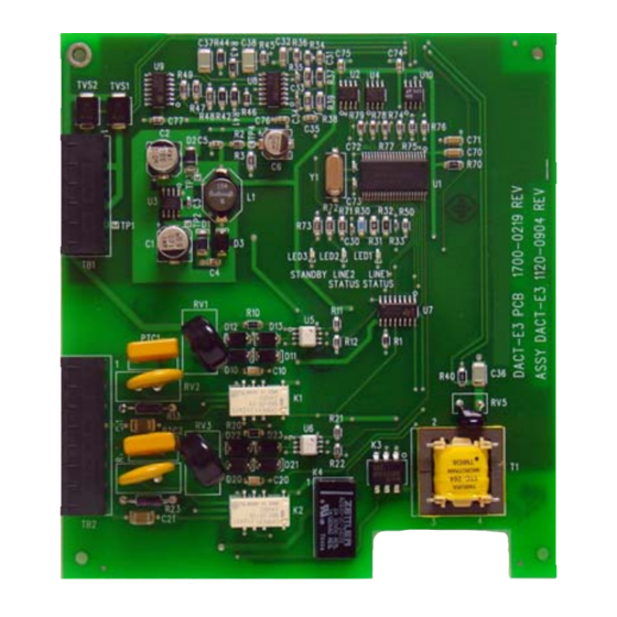
The DACT-E3 can be installed in a remote location via a local RS-485 interface. Figure 1.1 illustrates the DACT-E3 sub-assembly
and Figure 1.2 shows the DACT-E3 circuit board PCB.
Figure 1.1 DACT-E3 Transmitter Sub-Assembly
Document 9000-0581:J6
•
3+1 2300 Hz
•
4+2 1400 Hz
IF600 Retrofit B-Slim
•
600 XL Retrofit Kit
•
7200 Retrofit Kit
12/16/2019
ECN 19-0648
•
4+2 2300 Hz
•
3+1 1400 Hz
Retrofit Kits
TVS2 TVS1
+
+
TP1
TB1
PTC1
1
PTC2
TB2
Figure 1.2 DACT-E3 Transmitter PCB
•
Ademco Contact ID
S3 Series System
•
S3 Series (Small Addressable Panel)
+
LED3
LED2
LED1
STANDBY LINE2
LINE1
STATUS
STATUS
1
T1
1
4
Advertisement
Table of Contents

Related Manuals for Honeywell DACT-E3


Summary of Contents for Honeywell DACT-E3
-
Page 1: Section 1: Description
ILI95-MB-E3 (Intelligent Loop • 7200 Retrofit Kit Interface95-Main Board) The DACT-E3 can be installed in a remote location via a local RS-485 interface. Figure 1.1 illustrates the DACT-E3 sub-assembly and Figure 1.2 shows the DACT-E3 circuit board PCB. TVS2 TVS1 LED3... -
Page 2: Section 2: Installation
Use the Architects and Engineering Specifications for detailed information on your Facility’s Configuration. • Installers must be Gamewell-FCI Factory Certified to program this product. For additional information on this product, contact the Gamewell-FCI Customer Support to schedule the Factory Certified Training. DACT-E3 Product Installation Document — P/N 9000-0581:J6 12/16/2019... - Page 3 Cabinet D, Command Center Cabinet D, Voice Evacuation Note: For information on the DACT-E3 installation in the E3 Series, Fire, SLP or Retrofit Kits system cabinets and plates, refer to the S3 Series (Small Addressable FACP) System UL Listing Document, P/N: LS10005-051GF-E.
- Page 4 Insert and secure four screws (#4-40 x 1/4”) into the four standoffs as shown in Location 2 of Figure 2.3.1.1.1. NOTE: BACKBOX INSTALLATION: If the DACT-E3 is installed to the backbox, use four screws (#4-40 x 3/8”) and secure the screws into the four studs on the backbox.
- Page 5 Insert and secure four standoffs (3/16” HEX #4-40, x 1 1/) to the SLP-E3 as shown in Location 1 of Figure 2.3.1.2.1. Align and place the DACT-E3 on top of the SLP-E3. To mount the DACT-E3 to the SLP-E3, insert and secure four screws (#4-40 x 1/4”) into the four standoffs as shown in Location 2 of Figure 2.3.1.2.1.
-
Page 6: Specifications
Line 2 Ring OUT to phone Non power-limited* *Non power-limited Table 3.1 DACT-E3 Installation Wiring Terminals NOTE: For additional information on the DACT-E3, refer to the following document: ® - E3 Series (Expandable Emergency Evacuation System) Control Panel UL Listing Document, P/N: LS10080-051GF-E... - Page 7 Section 3: Wiring Connections (Continued) Figure 3.1 illustrates the wiring connections for the DACT-E3 sub-assembly. LED1 LINE 1 STATUS: = LINE 1 INACTIVE = LINE 1 TRANSMITTING DATA FLASHING = LINE 1 FAULT LED2 LINE 2 STATUS: = LINE 2 INACTIVE...
-
Page 8: Section 4: Formats And Codes
4.2.1 Standard Formats The DACT-E3 can be configured to allow each SLC device to report an event by selecting the DACT Reporting Feature. To define the Standard format for the ILI-E3/ILI95-E3 Series panel or SLP-E3 panel, enable the Standard Reporting Codes in the DACT Report Format Section of the DACT Settings screen in CAMWorks. - Page 9 Table 4.2.1.1 lists the DACT-E3 Contact ID Event Reporting Codes for the Standard Formats. Event Contact ID (Standard DACT Reporting Formats) FA [GGT] Fire Alarm (Smoke or Manual Station) 1 110 [0G] [GGT] 0 [T] FH [GGT] Fire Alarm Restored...
- Page 10 Table 4.2.1.1 DACT-E3 Contact ID Event Reporting Codes for Standard Formats 4.2.2 Custom Formats The DACT-E3 can be configured to allow each SLC device to report a unique 3-digit code by selecting the Custom DACT Reporting Feature. The user must specifically enable this feature through configuration programming by using CAMWorks™.
- Page 11 Table 4.2.2.1 lists the DACT-E3 Contact ID Event Reporting Codes for the Custom Formats. (See Note 3) Event (See Note 2) Contact ID (Custom DACT Reporting Formats) Fire Alarm (Smoke or Manual Station) FA (UUU) 1 110 (NN) (UUU) 0 (U)
- Page 12 Note 4: The UUU digits will always be 000 for events originating on the INI-7100, INI-VGC, INI-VGX, INI-VGE and NGA nodes. Note 5: The DACT-E3 reports the node number and 000 as the “UUU” digits if an event occurs on an SLC device that does not have a user- configured code assigned to it and the system is configured to report custom DACT codes.
-
Page 13: Telephone Requirements
Telephone Company to determine the maximum REN for the calling area. NOTE: Communication Line Test Requirement: To comply with UL 864 10th Edition, the System self-tests the communication line between the communicator and the receiver, 4-24 DACT Test Time Settings per day. DACT-E3 Product Installation Document — P/N 9000-0581:J6 12/16/2019... -
Page 14: Section 5: Reference Documentation
S3 Series (Small Addressable Fire Alarm Control Panel System), Operating Instructions LS10121-000GF-E E3 Series for the LCD-SLP Operating Instructions Table 5.1 Reference Documents Honeywell Gamewell-FCI 12 Clintonville Road Northford, CT 06472-1610 203.484.7161 9000-0581 | J6 | 06/20 www.gamewell-fci.com ©2020 Honeywell International Inc.