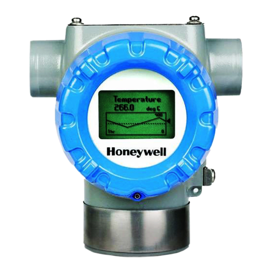

Related Manuals for Honeywell STT850 Series


Summary of Contents for Honeywell STT850 Series
- Page 1 STT850 Series HART/DE Option User’s Manual 34-TT-25-06 Revision 4.0 March 2016 Honeywell Process Solutions...
- Page 2 In no event is Honeywell liable to anyone for any indirect, special, or consequential damages. The information and specifications in this document are subject to change without notice.
-
Page 3: About This Manual
About This Manual This manual provides the details of programming Honeywell STT850 SmartLine Temperature Transmitters for applications involving HART versions 5, 6, and 7 and Honeywell’s Digitally Enhanced (DE) communication protocols. For installation, wiring, and maintenance information refer to the STT850 SmartLine Temperature Transmitter User Manual, document number #34-TT-25-03. - Page 4 Patent Notice The Honeywell STT850 SmartLine Temperature Transmitter family is covered by one or more of the following U. S. Patents: 5,485,753; 5,811,690; 6,041,659; 6,055,633; 7,786,878; 8,073,098; and other patents pending. Support and Contact Information For Europe, Asia Pacific, North and South America contact details, see back page or refer to the...
-
Page 5: Table Of Contents
Overview ........................24 4.4.2 DE Offline File Management ..................24 4.4.3 Save to a File ........................ 25 4.4.4 Downloading in DE Offline Mode ................25 4.4.5 DE Offline Parameterization ..................25 STT850 Series HART/DE Option User’s Manual Revision 4.0 Page v... - Page 6 Calibrating Analog Inputs ....................79 7.3.1 Correcting the Lower Range Value (LRV) ..............79 7.3.2 Correcting the Upper Range Value (URV) ..............80 7.3.3 Resetting Calibration....................80 7.3.4 STT850 Calibration Records ..................81 STT850 Series HART/DE Option User’s Manual Page vi Revision 4.0...
- Page 7 Device Information: ....................101 10.6.2 Model Number: ......................101 10.6.3 Device Assembly: ....................... 101 10.7 STT850 Offline Parameterization ..................102 HART DD Binary File Format Compatibility Matrix ............103 Glossary .............................. 104 STT850 Series HART/DE Option User’s Manual Revision 4.0 Page vii...
- Page 8 STT850 Series HART/DE Option User’s Manual Page viii Revision 4.0...
- Page 9 Figure 11 – Output Calibration Test Connections ................70 Figure 12 – DE Analog Mode Scaling and Test Connections .............. 70 Figure 13 – Setup to Manually Set the PV LRV and URV ..............73 STT850 Series HART/DE Option User’s Manual Revision 4.0 Page ix...
- Page 10 Table 27 – HART Critical and Non-Critical Diagnostic Details ............93 Table 28 – DE Diagnostic Messages ....................95 Table 29 – DE Critical and Non-Critical Diagnostic Details ............... 96 STT850 Series HART/DE Option User’s Manual Page x Revision 4.0...
-
Page 11: Stt850 Physical And Functional Characteristics
1 STT850 Physical and Functional Characteristics 1.1 Overview This section is an introduction to the physical and functional characteristics of Honeywell’s family of STT850 SmartLine Temperature Transmitters. 1.2 Features and Options The STT850 SmartLine Temperature Transmitter is available in a variety of models for measuring Thermocouples, RTD, Millivolts, and Volt or ohm sensor types. -
Page 12: Physical Characteristics
Figure 2 shows the assemblies in the Electronics Housing with available options. Figure 1 – STT850 Major Assemblies Figure 2 – Electronics Housing Components STT850 Series HART/DE Option User’s Manual Page 2 Revision 4.0... -
Page 13: Functional Characteristics
An optional 3-button assembly is available to set up and make adjustments to the Transmitter. In addition, a Honeywell Multi-Communication (MC) Toolkit (not supplied with the Transmitter) can facilitate setup and adjustment procedures in the case of HART and DE. Certain adjustments can be made through an Experion Station or a Universal Station if the Transmitter is digitally integrated with Honeywell’s Experion or TPS/TDC 3000 control system. -
Page 14: Local Display Options
For HART and DE you can also use the Honeywell MC Toolkit or other third-party hand-held to make any adjustments to an STT850 SmartLine Temperature Transmitter. Alternately, certain adjustments can be made through the Experion or Universal Station, if the Transmitter is digitally integrated with a Honeywell Experion or TPS system. -
Page 15: Optional 3-Button Assembly
Using increment, decrement & enter keys o A comprehensive on screen menu guides the way o Configure the transmitter o Configure the display o Set span Zero and span settings without optional display STT850 Series HART/DE Option User’s Manual Revision 4.0 Page 5... - Page 16 This page is left blank intentionally. STT850 Series HART/DE Option User’s Manual Page 6 Revision 4.0...
-
Page 17: Communication Modes
Figure 4 – DE Mode Value Scaling As indicated at the right of Figure 4, output values of process variables, as well as communications are transferred to a receiving device digitally. The digital coding is Honeywell proprietary, which requires the use of DE-capable Honeywell control equipment. -
Page 18: Hart Mode Communication
The FDC software application executing on the MCT404/202 supports the HART Universal, Common Practice and Device Specific Commands which are implemented in the Honeywell Transmitters. As indicated in Figure 5, the output of a Transmitter configured for HART protocol includes two primary modes: Figure 5 –... -
Page 19: Configuration Tools And Interfaces
Honeywell MC Toolkit or MCT404/202. The name MC Toolkit or Toolkit and MCT404/202 are used interchangeably as MCT404/202 is the model name for the Honeywell MC Toolkit product. -
Page 20: Mc Toolkit Participation
If you change a value and Transmitter power is interrupted before the change is copied to nonvolatile memory, the changed value will not be moved to nonvolatile memory. STT850 Series HART/DE Option User’s Manual Page 10 Revision 4.0... -
Page 21: Mc Toolkit-Transmitter Electrical/Signal Connections
Figure 6 displays how to connect the MC Toolkit directly to the terminals of a HART or DE Transmitter (top), and a HART-only Transmitter (bottom). Figure 6 – MC Toolkit-Transmitter Electrical/Signal Connections STT850 Series HART/DE Option User’s Manual Revision 4.0 Page 11... - Page 22 This page is left blank intentionally. STT850 Series HART/DE Option User’s Manual Page 12 Revision 4.0...
-
Page 23: De Transmitter Configuration
4 DE Transmitter Configuration 4.1 Configuration Personnel Requirements The configuration processes in this section reflect the assumption that you will use the Honeywell MC Toolkit Configuration Tool to configure an STT850 SmartLine Temperature Transmitter. The MC Toolkit application is used to configure Honeywell ST 3000 and SmartLine Pressure Transmitter, STT 3000 Smart Temperature Transmitters, as well as the STT850 SmartLine Temperature Transmitter. -
Page 24: De Transmitter Online Configuration
MCT404/202. The MC TOOLKIT Home page will be displayed. 3. Select the Online button, and establish communication between the Toolkit and the Transmitter. 4. When the warning message for connecting to a DE device appears, select OK. STT850 Series HART/DE Option User’s Manual Page 14 Revision 4.0... - Page 25 A confirmation request message will be displayed if you select <Back for a Transmitter that was previously set to Output Mode during calibration, and was not subsequently cleared. If you confirm the message (Yes answer), the display will exit the DE MAIN MENU. STT850 Series HART/DE Option User’s Manual Revision 4.0 Page 15...
-
Page 26: Device Information Configuration
Manufacturer’s firmware version identifier Firmware Version PROM ID Number PROM ID Number Scratch Pad Up to 32 alphanumeric characters Select the Back button to go back to the DE MAIN MENU. STT850 Series HART/DE Option User’s Manual Page 16 Revision 4.0... -
Page 27: General Configuration Parameters
STT850 SmartLine Temperature Transmitter User Manual for details. Line Filter Non-selectable: 50hz or 60hz. T/C Fault Select: Enabled or Disabled. Detect Select the Back button to go back to the DE MAIN MENU. STT850 Series HART/DE Option User’s Manual Revision 4.0 Page 17... -
Page 28: De-Specific Configuration Parameters
4.3.4.1 Notes on Damping (Digital Noise Reduction) You can adjust the damping time to reduce output noise. By way of suggestion, set damping to the smallest value reasonable for your process. STT850 Series HART/DE Option User’s Manual Page 18 Revision 4.0... -
Page 29: De Auxilary Configuration
4.3.5 DE Auxilary Configuration Auxiliary menu contains Latching status enable/disable option and also CJ compensation selection Select the Back button to go back to the DE MAIN MENU. STT850 Series HART/DE Option User’s Manual Revision 4.0 Page 19... -
Page 30: Monitor Status Configuration
Device Status button to display device status. Refer to the “Messages and Diagnostic Codes” section Communication Status of the MCT404/202 Toolkit manual. Select the Back button to go back to the DE MAIN MENU. STT850 Series HART/DE Option User’s Manual Page 20 Revision 4.0... - Page 31 Sensor 2 (C, F, R, K, Ohm, mV) Sensor Delta (C,F,R,K) PV Selection Sensor 1 Resistance (Ohm) Sensor 2 Resistance (Ohm) Loop Output (mA) Percent Output (%) STT850 Series HART/DE Option User’s Manual Revision 4.0 Page 21...
- Page 32 Display High Limit for Trend, Bar Graph - Usually equal to URV Bar High Limit Floating point value Duration of the trend screen in hours. Trend Duration Valid range 1 – 999 STT850 Series HART/DE Option User’s Manual Page 22 Revision 4.0...
-
Page 33: Saving The Configuration To File
New1. e. After entering the file name, select the Save button to display the DE MAIN MENU. STT850 Series HART/DE Option User’s Manual Revision 4.0 Page 23... -
Page 34: De Online Configuration Summary
In addition to file saving confirmation, DE offline file management provides access to three parameter sets for review and editing: Parameter Set 1 consists of the description of Transmitter according to bus type, device type, serial and model number, and the manufacturer. STT850 Series HART/DE Option User’s Manual Page 24 Revision 4.0... -
Page 35: Save To A File
Units, Damping, SV Units, Line Filter frequency, Sensor Type, and the output characterization selection. Parameter Set 3 is oriented primarily to the Honeywell SmartLine Temperature Transmitter models for monitoring purposes. 4.4.3 Save to a File Saving to a file in offline mode will let you add an edited configuration to a working file. Alternately, if you decide not to save an edited configuration to the current file, you can select a new location and file name for it. - Page 36 This page is left blank intentionally. STT850 Series HART/DE Option User’s Manual Page 26 Revision 4.0...
-
Page 37: Hart Transmitter Configuration
The other HART configuration Tools are Honeywell Experion in conjunction with FDM, iDTMs running on FDM or Pactware, and Emerson 375/475. The organization of Device Configuration and Parameter Descriptions on page 37 is given in Table 11. -
Page 38: Overview Of Fdc Homepage
Tap to select the highlighted menu option. Tap to quit FDC. Note: To select a particular option in FDC you can either select the option and then tap Select or you can directly double-tap the option. STT850 Series HART/DE Option User’s Manual Page 28 Revision 4.0... -
Page 39: Settings
With this option enabled, FDC creates necessary log files for troubleshooting and diagnostics. These files are stored in SD Card\FDC folder. Note: You must not enable this option unless suggested by Honeywell TAC because this may impact the application performance. -
Page 40: Manage Dds
If the DD file already exists, then the following message appears. Tap Yes to overwrite the existing DD files. If the DD file is added successfully, a success message appears. STT850 Series HART/DE Option User’s Manual Page 30 Revision 4.0... -
Page 41: Online Configuration
HART device with live communication. After making changes to the device you can also save a snapshot of the device data as history to later transfer it to FDM for record and audit purposes. STT850 Series HART/DE Option User’s Manual Revision 4.0 Page 31... -
Page 42: Offline Configuration
The workspace area on the device homepage consists of 4 tabs on the left hand side. Selecting a tab displays functions/information associated with that tab on the right hand side. Figure 8 – Device Homepage STT850 Series HART/DE Option User’s Manual Page 32 Revision 4.0... -
Page 43: Tabs On The Device Home Page
FDC across all devices. For the sake of explanations, the right side options under this tab shall be referred as “Entry points” throughout the rest of the document. STT850 Series HART/DE Option User’s Manual Revision 4.0 Page 33... - Page 44 Currently the only option it provides is called as Save History. Using this option you can save the snapshot of the device variables. This snapshot is saved in a format which can be later imported as a history record in FDM. STT850 Series HART/DE Option User’s Manual Page 34 Revision 4.0...
-
Page 45: Using Fdc For Various Device Operations
“Device Configuration” pages in this document. However it must be noted that this does not prohibit you from performing other device operations as explained above. STT850 Series HART/DE Option User’s Manual Revision 4.0 Page 35... - Page 46 Device Tab is shown. Based on the connected device type Menu items will be shown Navigate through the Menus to access various functions. See Table 11 for lists all the parameters in the STT850. STT850 Series HART/DE Option User’s Manual Page 36 Revision 4.0...
-
Page 47: Device Configuration And Parameter Descriptions
Diagram representing typical connections for Setup/Basic Setup/ power and communications for the STT850 System Connections Temperature Transmitter Online/Device Parts assembly diagram of an STT850 Setup/Basic Setup/ Temperature Transmitter STT850 Assembly STT850 Series HART/DE Option User’s Manual Revision 4.0 Page 37... - Page 48 URV: Upper Range Value(input which represents 100% output) Valid configurations for LRV and URV range from LTL to UTL. Model Number Displays the full order model number of the STT850 Temperature Transmitter STT850 Series HART/DE Option User’s Manual Page 38 Revision 4.0...
- Page 49 (analog output will operate as a 4 to 20 mA signal consistent with the Loop mA transmitter output) “Disable”: disables loop current mode (analog output will be fixed at 4 mA) STT850 Series HART/DE Option User’s Manual Revision 4.0 Page 39...
- Page 50 URV Correct calibrations. Correct LRV Records Displays the time and date history records for the last three LRV Correct calibrations. Reset Correct Records Displays the time and date history records for the STT850 Series HART/DE Option User’s Manual Page 40 Revision 4.0...
- Page 51 Analog Output PV AO % Displays a bar graph of the current value of the Analog Output PV % rnge Displays the current value of transmitter Output in % STT850 Series HART/DE Option User’s Manual Revision 4.0 Page 41...
- Page 52 Error Log Available to enable and disable error logging. If error log is enable all critical errors triggered will be logged with a time stamp. STT850 Series HART/DE Option User’s Manual Page 42 Revision 4.0...
- Page 53 - If the reconfigured value is greater than tamper attempts, then the tamper attempts value is retained. If the reconfigured value is smaller than tamper attempts, then the tamper attempts value is clamped to the reconfigured attempts. STT850 Series HART/DE Option User’s Manual Revision 4.0 Page 43...
- Page 54 “permanent.” If the lock is not permanent, it will be Setup/Detailed Setup cleared on power cycle or Master Reset of the device. If “Yes” is selected to unlock the device, the lock state will be cleared. STT850 Series HART/DE Option User’s Manual Page 44 Revision 4.0...
- Page 55 Poll Address: Select HART short address 0 to 63. Output Condition Num req preams: displays the number of required request preambles for the STT850 HART communications STT850 Series HART/DE Option User’s Manual Revision 4.0 Page 45...
- Page 56 = Sensor 1 input + Sensor 1 Bias. Sensor2 Config Sensor 2: Sensor 2 Config Parameters: Displays the Parameters basic configuration parameters and allows configuration of parameters relevant to Sensor 2, STT850 Series HART/DE Option User’s Manual Page 46 Revision 4.0...
- Page 57 Sensor 1 input exceeds the MRV value, allowing for hysteresis. Control then shifts to Sensor 2 and Output is ranged from MRV to URV. Control will shift back to the Sensor 1 and STT850 Series HART/DE Option User’s Manual Revision 4.0 Page 47...
- Page 58 CVD2 High Limit: A read only floating point value c) R0: A Floating Point Value d) Alpha: A Floating Point Value e) Delta: A Floating Point Value f) Beta: A Floating Point Value STT850 Series HART/DE Option User’s Manual Page 48 Revision 4.0...
- Page 59 CVD2 High Limit: A read only floating point value c) R0: A Floating Point Value d) Alpha: A Floating Point Value e) Delta: A Floating Point Value f) Beta: A Floating Point Value STT850 Series HART/DE Option User’s Manual Revision 4.0 Page 49...
- Page 60 PV. Scaling low/high limits: For Linear and Square Root scaling options, select the low and high scaling values. Custom Units: for Linear and Square Root STT850 Series HART/DE Option User’s Manual Page 50 Revision 4.0...
- Page 61 Number of Decimals: select the number of decimal places for the PV display from none to 3. Custom Tag: enter a custom tag name for the screen title up to 14 alphanumeric characters. STT850 Series HART/DE Option User’s Manual Revision 4.0 Page 51...
-
Page 62: Table 12 - Tamper Reporting Logic Implementation With Write Protect
Tamper Tamper Alert Configuration Jumper Status Software Status Reporting Status Posted? Change Allowed? The sections below give some examples as to how to edit the configuration parameters and execute Methods. STT850 Series HART/DE Option User’s Manual Page 52 Revision 4.0... -
Page 63: Procedure To Enter The Transmitter Tag
Shortcuts > Device Setup > Basic Setup > PV Units 2. Click Edit. You will be warned that if you change the value of the variable it will change the loop current, which may upset the control process. STT850 Series HART/DE Option User’s Manual Revision 4.0 Page 53... -
Page 64: Setting Pv Urv, And Lrv Range Values
13. Click Send. The Send to Device screen will be displayed. 14. Select the Range values check box, 15. Click Send to download the change to Transmitter, or Click Return to continue making changes. STT850 Series HART/DE Option User’s Manual Page 54 Revision 4.0... -
Page 65: Setting Range Values For Applied Temperature
To save device history, perform the following steps. On Device Home page, tap Tools. Select Save History and tap Select The Save History page appears. STT850 Series HART/DE Option User’s Manual Revision 4.0 Page 55... - Page 66 If a history record for this device already exists, the following warning message appears. Tap Yes to overwrite the existing name. A overwrite success message appears. Tap OK to return to Device Home page. STT850 Series HART/DE Option User’s Manual Page 56 Revision 4.0...
-
Page 67: Exporting Device History Records To Fdm
All operations allowed on Device History Record in FDM will be allowed for the record imported through the MC Toolkit handheld. Note: For more details on using FDM Import/Export feature, refer to section Importing and Exporting Device History in FDM User’s Guide. STT850 Series HART/DE Option User’s Manual Revision 4.0 Page 57... -
Page 68: Exporting Device History Records To Documint
Tap Ok. Tap Option>Save to persist the change Tap Return to return to My Views page. You would see two options with the names you gave to the newly created views. STT850 Series HART/DE Option User’s Manual Page 58 Revision 4.0... - Page 69 Edit the parameters that are Read / Write and select Send. For more details on any of the FDC features, refer the “MC Toolkit User Manual, document # 34-ST- 25-20.” STT850 Series HART/DE Option User’s Manual Revision 4.0 Page 59...
-
Page 70: Offline Configuration
Note: In case if the offline configuration template is already imported, an overwrite message appears. Tap OK to return to the Offline Configurations page. The device details appear on the bottom of the page. STT850 Series HART/DE Option User’s Manual Page 60 Revision 4.0... - Page 71 Tap OK to return to the offline wizard. Tap Next. The Offline – Review and Send page appears with the list of selected variables. STT850 Series HART/DE Option User’s Manual Revision 4.0 Page 61...
- Page 72 Note: If the variables are downloaded successfully, status appears as SUCCESS in green color; and if failed, status appears as FAILED in red color. Tap Finish to return to FDC Homepage. STT850 Series HART/DE Option User’s Manual Page 62 Revision 4.0...
- Page 73 This page is left blank intentionally. STT850 Series HART/DE Option User’s Manual Revision 4.0 Page 63...
-
Page 74: De Calibration
6.2 Calibration Recommendations If the Transmitter is digitally integrated with a Honeywell Total Plant Solution (TPS) system, you can initiate range calibration and associated reset functions through displays at the Universal Station, Global User Station (GUS), and Allen-Bradley Programmable Logic Controllers (PLCs). However, a range calibration using the MC Toolkit with the Transmitter removed from service is recommended. -
Page 75: Analog Output Signal Calibration
4. In the Output Calibration box, select the Loop Test button to display the LOOP TEST box. 5. Select the desired constant-level Output: 0 %, 100 %, or Other (any of 0 % - 100 %). STT850 Series HART/DE Option User’s Manual Revision 4.0... -
Page 76: Calibrating Range Using The Mc Toolkit
Corrections are applied at the Lower Range Value (LRV) and the Upper Range Value (URV). STT850 Series HART/DE Option User’s Manual Page 66 Revision 4.0... -
Page 77: Input Calibration Procedures Description
For the input calibration procedures, connect the test setup illustrated in Figure 10. Either voltage mode (Voltmeter across the resistor) or current mode (Ammeter in series with the resistor) is satisfactory. Figure 10 – Input Calibration Connections STT850 Series HART/DE Option User’s Manual Revision 4.0 Page 67... -
Page 78: Input Calibration Procedure
5. Observe the input Temperature at the applied value; when it is stable, select the OK button. 6. When the Transmitter has completed the LRV correction, this message appears: 7. Select OK to acknowledge. STT850 Series HART/DE Option User’s Manual Page 68 Revision 4.0... -
Page 79: Correct Input At Urv
2. Adjust the PV input Temperature to the exact value of the URV entered in the DE CONFIGURE display. 3. Select the OK button. 4. When the transmitter has completed the URV correction, this message appears. 5. Select OK to acknowledge. STT850 Series HART/DE Option User’s Manual Revision 4.0 Page 69... -
Page 80: De Output Calibration
URV of 100%. Figure 12 shows the PV scale and representative process system connections. Figure 12 – DE Analog Mode Scaling and Test Connections 1. Start the MC Toolkit application such that the DE MAIN MENU is displayed. STT850 Series HART/DE Option User’s Manual Page 70 Revision 4.0... - Page 81 Step Size to 10 or 100. e. After establishing the zero current level (4 mA), select Set Output To 100%. A meter reading of 20 mA corresponds to 5 volts. STT850 Series HART/DE Option User’s Manual Revision 4.0 Page 71...
- Page 82 If you want to stay in output mode while viewing other displays, select Yes; otherwise, select No and the Clear Output button. STT850 Series HART/DE Option User’s Manual Page 72 Revision 4.0...
-
Page 83: Manually Setting The Process Variable Range
1. Establish the test connections shown below. Then start the MC Toolkit application to display the DE MAIN MENU. Figure 13 – Setup to Manually Set the PV LRV and URV Select the Calibration button to display the CALIBRATION menu. STT850 Series HART/DE Option User’s Manual Revision 4.0 Page 73... - Page 84 Set URV. d. If the displayed value is satisfactory, select Yes to copy the Input Value to the URV in the Transmitter. If not, select NO and repeat this step. STT850 Series HART/DE Option User’s Manual Page 74 Revision 4.0...
-
Page 85: Procedure To Reset Calibration
DE MAIN MENU is displayed, and establish communication with the Transmitter. 2. From the DE MAIN MENU, select Calibration. The CALIBRATION menu will be displayed. Typical Calibration Menu. Based on the device model respective menu items will be shown. STT850 Series HART/DE Option User’s Manual Revision 4.0 Page 75... - Page 86 ("characterization") values. It is intended for use only when excessive corrections render the transmitter inaccurate. It is highly recommended that input calibration procedure be performed after calibration reset. STT850 Series HART/DE Option User’s Manual Page 76 Revision 4.0...
-
Page 87: Hart Calibration
Digital Voltmeter or millimeter with 0.02% accuracy or better MC Toolkit Calibration standard Temperature source with a 0.02% accuracy 250 ohm resistor with 0.01% tolerance or better. STT850 Series HART/DE Option User’s Manual Revision 4.0 Page 77... -
Page 88: Analog Output Signal Calibration
Return back to the ”Enter Meter Value” prompt until the field device output equals the reference meter Select Yes and press Enter 10. The prompt notifies you that the field device will be returned to its original output STT850 Series HART/DE Option User’s Manual Page 78 Revision 4.0... -
Page 89: Calibrating Analog Inputs
NOTE: If you are calibrating LRV and URV at the same time do not power down and start up again after the LRV steps, just go to step 1 of the URV procedure below. STT850 Series HART/DE Option User’s Manual Revision 4.0... -
Page 90: Correcting The Upper Range Value (Urv)
7. When the message “Reset Corrects OK” appears, press OK. The previous calibration “Corrects” are removed and calibration is reset to the factory values. 8. When prompted to return the loop to automatic control, press OK STT850 Series HART/DE Option User’s Manual Page 80 Revision 4.0... -
Page 91: Stt850 Calibration Records
Last URV2 Correct Date and Time of last URV2 correct done displayed in mm/dd/yyyy format Prev URV2 Correct Date and Time of previous URV2 correct done displayed in mm/dd/yyyy format STT850 Series HART/DE Option User’s Manual Revision 4.0 Page 81... - Page 92 Date and Time of last Reset corrects done for sensor2 displayed in mm/dd/yyyy format Prev Corrects Sensor2 Rec Date and Time of previous Reset corrects done for sensor2 displayed in mm/dd/yyyy format STT850 Series HART/DE Option User’s Manual Page 82 Revision 4.0...
-
Page 93: Hart Advanced Diagnostics
Set-up User enters a date once during device lifetime. Once date is entered no further updates are possible and value becomes read only and is permanently saved. STT850 Series HART/DE Option User’s Manual Revision 4.0 Page 83... -
Page 94: Pv Tracking Diagnostics
PV passed above “PV Upper Last PV Up Stress Limit” (in days, hours and minutes). None – initialized to zero prior to leaving Set-up the factory. Backup once each 7.5 hour period STT850 Series HART/DE Option User’s Manual Page 84 Revision 4.0... -
Page 95: Table 16 - Minimum Pv Tracking
Last PV Down value of “PV Lower Stress Limit” (in days, hours and minutes). None – initialized to zero prior to Set-up leaving the factory. Backup once each 7.5 hour period STT850 Series HART/DE Option User’s Manual Revision 4.0 Page 85... -
Page 96: Sv Tracking
Time Since Method Description Temperature has passed below the value of “SV Lower Last SV Stress Limit” (in days, hours, and minutes). Down Set-up None. Backup once each 8 hour period STT850 Series HART/DE Option User’s Manual Page 86 Revision 4.0... -
Page 97: Et Tracking Diagnostics
Time that has passed since the last time device’s Electronics Temperature has Last ET Up passed above the value of “ET Upper Stress Limit” (in days, hours and minutes). Set-up None. Backup once each 8 hour period STT850 Series HART/DE Option User’s Manual Revision 4.0 Page 87... -
Page 98: Stress Life
10% of respective range limits.% of Service life spent either in 10% of lower limit range or 10% of upper limit range. Set-up None. Backup once each 7.5 hour period STT850 Series HART/DE Option User’s Manual Page 88 Revision 4.0... -
Page 99: Service Life
“Time Since Last Event” to be Voltage Parameters reset to zero. Within a short period of time “Min Op Voltage” will assume operating voltage value. Set-up User actuates as desired. STT850 Series HART/DE Option User’s Manual Revision 4.0 Page 89... -
Page 100: Avdd Tracking Diagnostics
Sensor CPU time Sensor CPU Temperature has passed below the value of “Min Temp. Down Sensor CPU Temp” (in days, hours and minutes). Set-up none Backup once each 8 hour period STT850 Series HART/DE Option User’s Manual Page 90 Revision 4.0... -
Page 101: Power Up Diagnostics
Only one power failure in each 8 hour period is counted. Time since Method Description Displays time since last power-up in last power fail minutes. Set-up None. Backup once each 8 hour period– STT850 Series HART/DE Option User’s Manual Revision 4.0 Page 91... -
Page 102: Troubleshooting And Maintenance
Communication Module Over Temperature No DAC compensation Unreliable communication between Sensor and Comm Modules Display NVM fault Excess Delta (not available for DE) Internal Power failure for Communication Module (not available for DE) STT850 Series HART/DE Option User’s Manual Page 92 Revision 4.0... -
Page 103: Hart Diagnostic Details
NO FACTORY CAL calibrated by the factory. LOW: Supply voltage is below the low specification limit. Supply Voltage LOW OR HIGH HIGH: Supply voltage is above the high specification limit. STT850 Series HART/DE Option User’s Manual Revision 4.0 Page 93... - Page 104 LOW: Internal power is below 2.9V” Internal Power and “HIGH: Internal power is above (HART only) LOW OR HIGH 3.4V. ON or OFF State of the Digital Digital Output Output. STT850 Series HART/DE Option User’s Manual Page 94 Revision 4.0...
-
Page 105: De Diagnostic Message
Sensor Input 2 TB8 Open No Factory Calibration Supply voltage Fault (External Supply voltage Fail) Communication Module Over Temperature No DAC compensation Unreliable communication between Sensor and Comm Modules Display NVM fault STT850 Series HART/DE Option User’s Manual Revision 4.0 Page 95... -
Page 106: De Diagnostic Details
NO FACTORY CAL calibrated by the factory. LOW: Supply voltage is below the low specification limit. Supply Voltage LOW OR HIGH HIGH: Supply voltage is above the high specification limit. STT850 Series HART/DE Option User’s Manual Page 96 Revision 4.0... - Page 107 SUSPECT: The interface between the Temperature Sensor Module and Sensor Comm the Electronics Module is SUSPECT experiencing intermittent communication failures. Display Setup NVM Corrupt: The Display memory is HART/DE only NVM Corrupt corrupt. STT850 Series HART/DE Option User’s Manual Revision 4.0 Page 97...
-
Page 108: Using Dtms
MC Toolkit FDC application. Refer to Table 11 for a complete listing of all the parameters and details. In the following sections, emphasis is given to show the various DTM screens. STT850 Series HART/DE Option User’s Manual Page 98... -
Page 109: Stt850 Online Parameterization
10.5 STT850 Online Parameterization On selecting Parameter/Online Parameterization, the DTM home page will be displayed. Typical home page screen is shown below. Based on the device type respective parameters will be shown. STT850 Series HART/DE Option User’s Manual Revision 4.0 Page 99... -
Page 110: Device Health
Basic Setup: Provides Device Setup information (Tag, Device Type, MB Type etc.) Calibration: Provides access to all the Calibration functions Refer to the Table 11 for more details STT850 Series HART/DE Option User’s Manual Page 100 Revision 4.0... -
Page 111: Basic Setup Page
Provides access to Message, Clear Message and Maint Mode. Refer to Table 11 for more details 10.6.2 Model Number: Shows the Model number. 10.6.3 Device Assembly: Shows the Blow out Image of STT850. STT850 Series HART/DE Option User’s Manual Revision 4.0 Page 101... -
Page 112: Stt850 Offline Parameterization
10.7 STT850 Offline Parameterization On selecting Parameter/ Parameterization, the Offline parameter configuration page will be displayed. Select Device / Load to Device to download the Offline Configuration to the connected device. STT850 Series HART/DE Option User’s Manual Page 102 Revision 4.0... -
Page 113: Hart Dd Binary File Format Compatibility Matrix
Experion R400 to R300 Experion below R300 FDM R430 FDM R410 – R302 FDM Below R302 Refer the respective Tools’ User Manual for details on loading the DD file on these Tools. STT850 Series HART/DE Option User’s Manual Revision 4.0 Page 103... -
Page 114: Glossary
Smart Field Communicator STIM Temperature Transmitter Interface Module STIMV IOP Temperature Transmitter Interface Multivariable Input/Output Processor Thermocouple Upper Range Limit Upper Range Value Universal Station Volts Alternating Current Volts Direct Current STT850 Series HART/DE Option User’s Manual Page 104 Revision 4.0... - Page 115 STT850 Series HART/DE Option User’s Manual Revision 4.0 Page 105...
- Page 116 Online configuration ..........38 Transmitter Adjustments ........12 Overview of Device Homepage ........ 39 Procedure to Enter the Transmitter Tag ....See Setting PV URV, and LRV Range Values ....60 STT850 Series HART/DE Option User’s Manual Page 106 Revision 4.0...
- Page 117 Using DTMs ..............104 Basic Setup Page ............ 107 Downloads ............. 104 Procedure to Install and Run the DTM ....104 STT800 Offline Parameterization ......108 STT850 Online Parameterization......105 STT850 Series HART/DE Option User’s Manual Revision 4.0 Page 107...
- Page 118 Phone: +(822) 799 6114 Fax: +(822) 792 9015 For more information To learn more about SmartLine Transmitters, visit www.honeywellprocess.com Or contact your Honeywell Account Manager Process Solutions Honeywell 1250 W Sam Houston Pkwy S Houston, TX 77042 Honeywell Control Systems Ltd...