Table of Contents
Advertisement
Quick Links
Models: PC1_ or PC2_ with FoamLogix 3.3, 5.0 or 6.5 and
SmartCAFS200 (from September 2010)
Installation and Operation Manual
Godiva Ltd.
A Unit of IDEX Corporation
Charles St
Warwick CV34 5LR
England
+44 (0)1926 623600
+44 (0)1926 623666 / 623689
www.godiva.co.uk
godiva@idexcorp.com
Prima
Pump with Integrated
GP/276
Issue 6, January 2014
Advertisement
Table of Contents

Related Manuals for Idex Godiva Prima SmartCAFS PC1 Series


Summary of Contents for Idex Godiva Prima SmartCAFS PC1 Series
- Page 1 Pump with Integrated Models: PC1_ or PC2_ with FoamLogix 3.3, 5.0 or 6.5 and SmartCAFS200 (from September 2010) Installation and Operation Manual Godiva Ltd. A Unit of IDEX Corporation Charles St Warwick CV34 5LR England +44 (0)1926 623600 +44 (0)1926 623666 / 623689 ...
-
Page 2: Amendment Record
AMENDMENT RECORD Model: PC1_ or PC2_ with FoamLogix 3.3, 5.0, 6.5 Systems and SmartCAFS200 Control Date Page/s Amendment New Issue September New Issue Issue 1, 2010 Gauges – do not use solvents. Use mild detergent and August 7, 44 Issue 2 2011 water Additional diagram –... -
Page 3: Table Of Contents
CONTENTS AMENDMENT RECORD ......................2 CONTENTS ..........................3 INTRODUCTION ........................6 IMPORTANT NOTES ......................6 SAFETY - RELEVANT DATA ....................7 ........................7 AINTENANCE ..........................7 RAINING ........................7 AFETY OINTS ............................ 7 OISE ......................7 LUTCH NGAGEMENT ENVIRONMENTAL PROTECTION ..................8 GENERAL DATA ........................ - Page 4 HEN THE GEARBOX IS IN THE VERTICAL POSITION AN OIL FILL POINT AND OIL LEVEL CHECK POINT ............... 21 ARE LOCATED ON BOTH SIDES OF THE HOUSING EARBOX ILLING AND EVEL HECKING ORIZONTAL OSITION EFT OR IGHT OF PUMP ....................
- Page 5 PUMP OPERATING FAULTS 2 – EXCESSIVE PUMP NOISE ........... 49 GENERAL OPERATING FAULTS - CAFS ................50 AIR INJECTION FAULTS ....................51 RECOMMENDED SPARES KIT FOR BI-ANNUAL SERVICE ..........54 ..........................54 OTES INSTALLATION DRAWINGS – PC2_ WITH SMARTCAFS200 ........... 55 1A ( PC2_4010) ..................
-
Page 6: Introduction
INTRODUCTION This manual contains information relevant to Godiva single or multi-pressure Prima Series Pumps, when partnered with Compressed Air Foam Systems (CAFS) FoamLogix Models 3.3, 5.0 and 6.5 and the SmartCAFS200 control system. Distinction between the models regarding Installation, Maintenance, Operation and Specification is clearly noted with text and illustrations. -
Page 7: Safety - Relevant Data
SAFETY - RELEVANT DATA Thank you for purchasing a Godiva Pump. Godiva Pumps are designed to give safe and reliable service. BEFORE use however, it is essential that the Operating and Installation Instructions are carefully read and understood. Maintenance It is the responsibility of the user to ensure that the equipment is maintained in a safe operational condition. -
Page 8: Environmental Protection
ENVIRONMENTAL PROTECTION It is prohibited to pour engine oil and other contaminants onto the ground, down sewers, drains, or into water courses. Dispose of lubricants through authorised waste disposal contractors, licensed waste disposal sites, or to the waste reclamation trade. If in doubt, contact your Local Environmental Agency for advice regarding disposal policies. -
Page 9: General Data
GENERAL DATA Compressor Model Enduro 12 Maximum Operating Speed 6500 rev/min Nominal speed of operation 5000 rev/min Nominal power consumption 40.0kW Direction of rotation Anti-clockwise (viewed on pulley) Volume output 5650 l/min Operational pressure range 4 to 10 bar Pump Minimum idle speed 900-1000rpm Cooling System... -
Page 10: Lubricants
LUBRICANTS Compressor Recommended: Screw compressor oil in compliance with ISO Viscosity grade 32 to 46. Alternative: SAE 10W/40 automotive multigrade oil. Capacity 12 litres Pump Gearbox Recommended: BP Energol GR XP 68 or similar Capacity 1.2 litres approximately Pump Bearing Housing Recommended: 10W/40 or 15W/40 Multi-grade engine oil. -
Page 11: Recommended Foam Agents
RECOMMENDED FOAM AGENTS Hale FoamLogix Models 3.3, 5.0, 6.5 can be used with the foam concentrates specified on the Hale Foam Proportioning System Foam Concentrate Compatibility List provided at the rear of this manual, Hale Bulletin #650, Rev 32 , 7-17-07. The foam concentrates in the list have been tested by Hale Products to ensure compatibility with FoamLogix systems. -
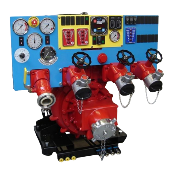
Page 12: Major Components And Controls
MAJOR COMPONENTS AND CONTROLS General Arrangement Rotary twin screw compressor Mounting platform, incorporates PTO driven Gearbox with Integral gearbox oil cooler forklift points, anti-vibration compressor drive via an mountings and fluid drain points electromagnetic clutch Interlock for Compressor Clutch Control Models built from mid-2013 are fitted with a solid state device complete with pressure switch indicating LEDs and compressor hours run meter. -
Page 13: Foamlogix 3.3, 5.0, 6.5 Foam Pump Component Group
FoamLogix 3.3, 5.0, 6.5 Foam Pump Component Group Note: Hale FoamLogix 3.3, 5.0 or 6.5 foam pump is supplied loose for mounting by vehicle builder. FoamLogix 3.3 shown Dual Tank Literature Selector Pack (mandatory option) Control Head Harness (fitted to pump) Dual Tank Selector Extension... -
Page 14: Control Panel Foamlogix 3.3, 5.0, 6.5 - Typical
Control panel FoamLogix 3.3, 5.0, 6.5 - typical NB: Options and gauge types may vary. 18 19 11 12 13 11 12 13 Engine speed control - Up = increase, Down = decrease, Left or right = pre-set speeds. Vehicle status lamps: Engine - high coolant temperature. Engine - low oil pressure Vehicle - low battery charge. -
Page 15: System Overview
SYSTEM OVERVIEW The PC1_ or PC2_ is a Compressed Air Foam System comprising of three major components (in addition to the main water pump) – Air compressor (with separate heat exchanger and oil/water separator), FoamLogix (foam proportioning unit) and manifold (foam mixing and control system). -
Page 16: Foamlogix - Foam Proportioning System
Manifold The manifold incorporates an air ratio control valve through which degrees of wet or dry foam mixture can be selected. Compressed air is then injected and the resulting foam / water / air combination is thoroughly mixed by the X-mixers during discharge. A By-pass valve is fitted to help obtain the required dry foam flow rate, this valve is adjusted and set during the installation stage, it is not required during normal operation. -
Page 17: Installation And Initial Set-Up
INSTALLATION AND INITIAL SET-UP The following connection points should be considered when installing the PC1_ or PC2_ assembly into a vehicle. Lifting Points Secure handling of the unit for installation and maintenance is vital. Use only the lifting points provided on the unit. Fork Lift points ©Godiva Ltd. -
Page 18: Foamlogix 3.3, 5.0, 6.5 System - Remote Mounted
FoamLogix 3.3, 5.0, 6.5 System – Remote Mounted (Model 3.3 shown) By-pass valve and connection point (on reverse of valve) To foam injection point on manifold. 13mm (1/2inch) NPT Tubing suitable for 22.5 bar pressure Inlet from foam tank, Models 3.3, 5.0 – 19mm (3/4inch) NPT Model 6.5 –... -
Page 19: Fluid Drain Points
Fluid Drain Points Pump bearing housing, and gearbox oil drain points are located at the lower left side of the pump (viewed from the suction tube end). Gearbox coolant and the pump drain points are located at the lower right hand side of the pump. -
Page 20: Oil Filling Points
Oil Filling Points The unit is supplied without oil and must be filled with the correct quantity and specification before starting the pump. Bearing Housing The oil filling point for the pump bearing housing is located on the right side of the pump (viewed from suction tube). -
Page 21: Gearbox Oil Filling And Checking - Vertical Position
Gearbox Oil Filling and Checking – vertical position When the gearbox is in the vertical position, an oil fill point and oil level check point are located on both sides of the housing. Gearbox oil fill point Gearbox oil level check point Fill the gearbox until the oil flows from the oil level check point. -
Page 22: Gearbox Oil Filling And Level Checking - Horizontal Position, Left Or Right Of Pump
Gearbox Oil Filling and Level Checking - Horizontal Position, Left or Right of pump The oil filling point is on the side of the casing (LH gearbox shown) and is symmetrically opposite for RH gearbox. The oil level check point is lower on the side. Oil capacity and type as Down position detail. Fill the gearbox until the oil flows from the oil level check point. -
Page 23: Compressor Drive Belt
Compressor Drive Belt The compressor is driven by a Goodyear Eagle PD synchronous drive belt.. The installer must allow for access to adjust the belt tensioner. Tension the belt to achieve a 5mm deflection with a load of 145N (new belt) or 108N (used belt) applied at mid span, see photograph below. -
Page 24: Separator Tank For Compressor Oil
Separator Tank for Compressor Oil Note. Separator must be installed in the vertical position as shown. Pipework from compressor to oil tank must be arranged so that any oil in the compressor will drain back to the tank. Compressor Oil Cooling Unit ©Godiva Ltd. -
Page 25: Smartcafs Mixing Manifold
SmartCAFS Mixing Manifold Wet/dry foam setting valve Flow sensor Foam injection Water flow 3” Victaulic Air injection By-pass valve lever connection point for setting dry foam (Both ends, not consistency shown) Manifold should be mounted with provision for drainage. Foam and air injection points identified above. By-Pass Valve This valve is adjusted to give the required dry foam flow-rate - typically 100 litres/minute. -
Page 26: Schematic - Cafs Fluid
Schematic - CAFS Fluid ©Godiva Ltd. Our policy is one of continuous development. We therefore reserve the right to amend specifications without notice or obligation. - Page 27 Schematic – Plumbing Connections – Part 1 FOAM AIR and OIL WATER for numbers in circles see photographs on page 27 ©Godiva Ltd. Our policy is one of continuous development. We therefore reserve the right to amend specifications without notice or obligation.
-
Page 28: Compressor And Separator Tank - Relative Positions In Installation
Compressor and Separator tank – Relative positions in installation Please observe the relationship between compressor air/oil outlet and separator air/oil inlet connections when installing 212.5 62.5 1000 1050 237.5 Example – 87.5 1100 If distance A is 300mm, then distance B 1150 262.5 must be at least 50mm... -
Page 29: Schematic - Plumbing Connections - Part 2
Schematic – Plumbing Connections – Part 2 1. Oil scavenge line from separator tank to 6mm connection on rear of compressor 2. Air supply from separator tank to compressor, 6mm tubing/connector. 3. Air pressure for pump functions, connect from vehicle supply with 6mm tubing - 3.1 - High Pressure discharge, pneumatic operation of valve - if option fitted. -
Page 30: Smartcafs200 Wiring Harness - With Kzco Actuator Eh5 Prima
SmartCAFS200 Wiring Harness – with KZCO Actuator EH5 Prima ©Godiva Ltd. Our policy is one of continuous development. We therefore reserve the right to amend specifications without notice or obligation. -
Page 31: Foam Pump Harness Diagram
Foam Pump Harness Diagram Circuit Colour Power Pink Can high Yellow Can Shld Black Tank A Select Blue Tank B Select White Tank A Low Violet Tank B Low Gray Sensor supply Brown Ind sensor signal Black Sensor GND Blue Can Low Green Ground 2... - Page 32 SmartCAFS200 Wiring Harness Circuit Colour Circuit Colour SW No Orange GND Ref PAD Black Remote LED (-) Remote LED (+) Blue Pos Ref PAD SW Common Black Sign Pad WHL White Requires connection to foam pump Circuit Colour FoamLogix control head harness Can high Yellow Part numbers 113436, 113437, 113438,...
-
Page 33: Prima Smartcafs Engine Control Schematic
Prima SmartCAFS Engine Control Schematic Vehicle builder to use a 10amp fuse in power supply +24V +24V +24V +24V +24V +24V +24V FAST PRESET 2 SLOW COLOUR KEY (MAIN/TRACER) B = BLACK B/R = BLACK/RED N = BROWN B/W = BLACK/WHITE U = BLUE R/W = RED/WHITE W = WHITE... -
Page 34: Additional Installation Points
Foam Tank Low Level Sensor The unit is supplied with a connector for a low foam level sensor. The sensor is supplied with the unit ready for installation (instructions supplied with the sensor). The low foam level sensor is part of the Safety Interlock system and must be installed. Note: The low foam level sensor must be installed in the tank in the correct orientation. -
Page 35: Vehicle Design Considerations
VEHICLE DESIGN CONSIDERATIONS The following information is included to assist the vehicle builder to achieve a successful installation. The in-line foam strainer / valve assembly is a low-pressure device, rated at 3 bar and will NOT withstand high flushing water pressure. Seal all electrical power and ground connections with silicone sealant to prevent corrosion. -
Page 36: Installation And Initial Set-Up Foamlogix 3.3/5.0/6.5
INSTALLATION AND INITIAL SET-UP FOAMLOGIX 3.3/5.0/6.5 For foam pump installation, please refer to the FoamLogix Model 3.3/5.0/6.5 Description, Installation and Operation manual, part number 029-0021-68-0, supplied separately. Optional fitting - For further information on the MDTII Manual Tank Selector, please see the separate manual supplied, part number 029-0020-40-0. -
Page 37: Operation
OPERATION Caution: PC2_ or PC1_ pumps should only be used when working from open water or a tank feed. NEVER USE CAFS WITH A PRESSURE FEED INTO THE EYE OF THE PUMP. Problems will occur with the water / air pressure ratio, should pressurised (hydrant) water supply be applied directly to the suction tube. -
Page 38: Calibration Of Foamlogix
Select simulated flow on the FoamLogix by pressing both up ↑ & down ↓ at the same time. Press the on button, and the pump will prime itself. The pump will run for 30 seconds or until prime is achieved. If no prime is made, the display will show “no pr”. Repeat this step once more to attempt to prime the pump. -
Page 39: Wet And Dry Buttons
WET and DRY buttons The WET (or DRY) button is used to position the air ratio control valve at the preset position for the desired CAFS consistency. The WET button will open the valve to its WET preset position, and the DRY button will close the valve to its DRY preset position. The Smart Switch Panel will only open or close the valve within the operating range dictated by the preset WET and DRY limits calibrated by the factory. -
Page 40: Valve Position Bargraph Indicator (Leds)
Valve position bargraph indicator (LEDs) The valve position bargraph indicates the relative position of the valve in reference to the WET (open) and DRY (closed) presets. Fully WET (open) will light all six (6) bars and fully DRY (closed) will light only the bottom bar. Note: turning off the FoamLogix or disengaging the compressor will send the Air Ratio Control valve to the extreme WET position. -
Page 41: Foamlogix Control Panel
FoamLogix Control Panel Engaging PTO & Priming Main Pump 1. To ensure a clean pump prime and delivery when running from the tank, leave the pump wet, or if the pump is drained, run the pump at idle until a vacuum of approximately -0.5 bar is achieved and then slowly open the tank to pump valve. -
Page 42: Discharging Foam / Water Solution Only
Discharging Foam / Water Solution Only (May be operated from open water, tank, or hydrant into pump suction) 1. Engage the main pump PTO, open the tank to pump valve and set the pump at required pressure. 2. Ensure that the foam only option is selected by pressing the bottom of the Foam / Selector switch, marked with the symbol –... -
Page 43: Overheat Shut Down
6. Increase pump speed to required operating pressure (4-10 Bar). The system should not be operated outside these pressures. For dry foam the best pressure setting is 6-7 Bar. When air is being injected into the manifold, the air injection indicator will be illuminated (item 13, page 15). -
Page 44: Maintenance Schedule Pc2_/Pc1
MAINTENANCE SCHEDULE PC2_/PC1_ Note: The Godiva Compressor service intervals replace those in the Gardner Denver Compressor manuals EQUIPMENT ACTION PROCEDURE EVERY 3 MONTHS PC1_/PC2_ Check the pump and gearbox oil levels Pages 20-22 Do a vacuum test to test for leaks Page 46 PC2_ Clean the high pressure filter... -
Page 45: Maintenance Operations Pc2
IMPORTANT! In high usage or abnormal operating conditions, the above procedures may need to be more frequent. The best practise is to flush the system after each use. MAINTENANCE OPERATIONS PC2 Strainer - High Pressure 1) Remove strainer / Cap assembly 2) With care, remove debris from the strainer by washing. -
Page 46: Maintenance Operations Pump - Pc1 Or Pc2
MAINTENANCE OPERATIONS PUMP – PC1 OR PC2 CAFS Mixing Manifold – Greasing Ball Valve The CAFS Mixing Manifold contains a ball valve as part of the air ratio control system. This ball valve must be maintained by inserting lubricating grease at three monthly intervals to ensure smooth and efficient operation. -
Page 47: Thermal Relief Valve (Trv) Test - If Option Fitted
Apply a water pressure of 3.5 - 7.0 bar to the pump and check for leaks. The area causing the leak should be visible, and can be dismantled and rectified. If no leaks are apparent, the leakage must lie between the priming valve and the primer. Points to be checked are: The inlet seal in the primer end cap The priming valve diaphragm Thermal Relief Valve (TRV) Test –... -
Page 48: Fault Finding
FAULT FINDING PUMP OPERATING FAULTS 1 – LOSS OF SUCTION Loss of Suction All suction Suction lift Tighten all Reduce connectio too deep? connections suction lift ns air Air leaks in system system? Do a Vacuum Test Do a Pressure Test Trace leaks, rectify and retest pump Suction is restored... -
Page 49: Pump Operating Faults 2 - Excessive Pump Noise
PUMP OPERATING FAULTS 2 – EXCESSIVE PUMP NOISE Pump makes excessive rattling noise during operation Probably due to pump cavitation Decrease pump speed Has noise Continue using disappeared the pump Reduce suction lift Has noise Continue using disappeared the pump Investigate further –... -
Page 50: General Operating Faults - Cafs
GENERAL OPERATING FAULTS - CAFS No water Check oil cooler Compressor supply or pipework for Overheating restricted flow obstructions No Foam FoamLogix Switch on FoamLogix Solution not operating concentrate in Refill the foam tank foam tank Foam pump Prime the foam pump not primed Chatter/ Depleted... -
Page 51: Air Injection Faults
AIR INJECTION FAULTS No Air Injection Turn on FoamLogix and FoamLogix set the required turned on? Is CAFS Turn on CAFS turned on? Check drive belt compressor running? Check power supply to clutch Disconnect Is Foam Low Level Low Level Fill foam tank Switch to Switch... - Page 52 AIR INJECTION FAULTS continued Continued from previous page Does flow Does flow Test flow register when register when sensor and discharging discharging wiring liquid? liquid? connections Refer to Troubleshooting in FoamLogix Manual Is solenoid Does air Press test seeing +12/24V Replace the injection button on...
- Page 53 Godiva Prima pump illustrated parts list Please refer to: Godiva Ltd. publications: PC2 model – GP/258 Compressor illustrated parts list Please refer to: Gardener Denver Enduro 12 manual. Foamlogix illustrated parts list Please refer to: FoamLogix Model 3.3/5.0/6.5 Description, Installation and Operation manual, part number 029-0020-68-0.
-
Page 54: Recommended Spares Kit For Bi-Annual Service
RECOMMENDED SPARES KIT FOR BI-ANNUAL SERVICE Item Unit Comment Compressor Filter - Oil 70025 Filter - Air 010-0690-00-0 Belt - Drive 61291 Tensioner assembly - Belt drive 61198/002 PC2_ / PC1_ Strainer - Hi Pressure 60051 Not PC1_ series Washer - Dowty - Oil drain UFP 2303/08 Washer - Dowty - High Pressure UFP 2303/15... -
Page 55: Installation Drawings - Pc2_ With Smartcafs200
INSTALLATION DRAWINGS – PC2_ WITH SMARTCAFS200 Figure 1A (based on PC2_4010) ©Godiva Ltd. Our policy is one of continuous development. We therefore reserve the right to amend specifications without notice or obligation. - Page 56 Figure 1B (based on PC2_4010) ©Godiva Ltd. Our policy is one of continuous development. We therefore reserve the right to amend specifications without notice or obligation.
-
Page 57: F 1C ( Pc2_4010)
Figure 1C (based on PC2_4010) See page 64 ©Godiva Ltd. Our policy is one of continuous development. We therefore reserve the right to amend specifications without notice or obligation. - Page 58 Figure 1D (based on PC2_4010) ©Godiva Ltd. Our policy is one of continuous development. We therefore reserve the right to amend specifications without notice or obligation.
- Page 59 Figure 1E (based on PC2_4010) ©Godiva Ltd. Our policy is one of continuous development. We therefore reserve the right to amend specifications without notice or obligation.
-
Page 60: F 1F ( Pc2_4010)
Figure 1F (based on PC2_4010) ©Godiva Ltd. Our policy is one of continuous development. We therefore reserve the right to amend specifications without notice or obligation. - Page 61 Figure 2A Manifold ©Godiva Ltd. Our policy is one of continuous development. We therefore reserve the right to amend specifications without notice or obligation.
- Page 62 Figure 2B Manifold ©Godiva Ltd. Our policy is one of continuous development. We therefore reserve the right to amend specifications without notice or obligation.
- Page 63 Figure 3A Cooling Cool water supply Oil outlet to inlet from pump compressor Water return to Oil inlet from separator tank pump suction line ©Godiva Ltd. Our policy is one of continuous development. We therefore reserve the right to amend specifications without notice or obligation.
-
Page 64: F 3B C
Figure 3B Cooling ©Godiva Ltd. Our policy is one of continuous development. We therefore reserve the right to amend specifications without notice or obligation. -
Page 65: F 4A O S
Figure 4A Oil Separator ©Godiva Ltd. Our policy is one of continuous development. We therefore reserve the right to amend specifications without notice or obligation. - Page 66 Figure 4B Oil Separator See page 55 ©Godiva Ltd. Our policy is one of continuous development. We therefore reserve the right to amend specifications without notice or obligation.
-
Page 67: F 5A F L D
Figure 5A FoamLogix Dimensions Fig 5B FoamLogix Baseplate mounting hole locations ©Godiva Ltd. Our policy is one of continuous development. We therefore reserve the right to amend specifications without notice or obligation. -
Page 68: Recommended Foam Agents
RECOMMENDED FOAM AGENTS Class A Foam Manufacturer Brand name Forestry Service ANSUL Silvex Class Foam Approved Concentrate Angus Forexpan S (0.1% - 1.0%) Chubb National Foam Defense Class Coldwater Foam Chubb National Foam Knock-Down Monsanto Phoscheck WD881 Chemonics Fire-Trol Fire Foam 103 Chemonics Fire-Trol Fire Foam 104 Light Water FT-1150...