
Related Manuals for Honeywell Notifier NFN-GW-EM-3


Summary of Contents for Honeywell Notifier NFN-GW-EM-3
- Page 1 NFN-GW-EM-3 Installation and Operation Manual NFN-GW-EM-3 Installation and Operation Manual Document LS10017-000NF-E 6/5/2014 Rev: P/N LS10017-000NF-E:C3 ECN 14-0243...
- Page 2 Fire Alarm & Emergency Communication System Limitations While a life safety system may lower insurance rates, it is not a substitute for life and property insurance! An automatic fire alarm system—typically made up of smoke (caused by escaping gas, improper storage of flammable materi- detectors, heat detectors, manual pull stations, audible warning als, etc.).
- Page 3 Datapoint Corporation. Microsoft and Windows are registered trademarks of the Microsoft Corporation. © 2014 by Honeywell International Inc. All rights reserved. Unauthorized use of this document is strictly prohibited. NFN-GW-EM-3 Installation and Operation Manual – P/N LS10017-000NF-E:C3 6/5/2014...
- Page 4 Documentation Feedback Your feedback helps us keep our documentation up-to-date and accurate. If you have any comments or suggestions about our on-line help or manuals, please e-mail us at FireSystems.TechPubs@honeywell.com. On-Line Help – Please include the following information: • Product name and version number (if applicable) •...
-
Page 5: Table Of Contents
Table of Contents Section 1 Product Overview ....................7 1.1: Operation ...............................7 1.2: Functionality ..............................7 1.3: Required Software ............................7 1.4: Environmental Requirements ........................7 1.5: System Architecture............................8 Figure 1.1 Direct Panel Architecture......................8 Figure 1.2 Single NFN Network Architecture ..................8 Figure 1.3 Multiple NFN Networks Architecture ..................9 1.5.1: Redundancy ............................10 Figure 1.4 Redundant NFN-GW-EM-3s ....................10 1.6: IP Requirements............................11... - Page 6 Table of Contents 3.2.4: Product Information...........................25 3.2.5: Additional Properties.........................26 3.2.6: Node List ............................27 3.3: Security Certificate ............................28 Figure 3.2 Chrome Security Warning Example ...................28 Appendix A: Gateway Settings....................29 A.1: Viewing Existing IP Settings ........................29 A.2: Resetting Factory Default Values .......................29 NFN-GW-EM-3 Installation and Operation Manual –...
-
Page 7: Section 1 Product Overview
Section 1 Product Overview 1.1 Operation ® ® ™ The NFN-GW-EM-3 serves as a bridge between an ONYXWorks Workstation or ONYX IRST ISION and the connected NFN or high-speed NFN network. The NFN-GW-EM-3: • Functions as a node on an NFN network and communicates the NFN network’s panel and device data ®... -
Page 8: System Architecture
Product Overview System Architecture 1.5 System Architecture An Internet or Intranet IP network connection is used with the architectures described in Figures 1.1, 1.2, and 1.3. Connection IP Network Ethernet Ethernet NFN-GW-EM-3 Workstation FACP Figure 1.1 Direct Panel Architecture IP Network Ethernet Ethernet Workstation... - Page 9 System Architecture Product Overview IP Network Ethernet Ethernet PC Gateway with Workstation Workstation Ethernet Ethernet NFN-GW-EM-3 Workstation HS-NCM NFN Network NFN Network FACP FACP FACP FACP FACP FACP Figure 1.3 Multiple NFN Networks Architecture NFN-GW-EM-3 Installation and Operation Manual – P/N LS10017-000NF-E:C3 6/5/2014...
-
Page 10: 1: Redundancy
Product Overview System Architecture 1.5.1 Redundancy A redundant gateway is a second gateway which communicates with an NFN network. If the main gateway cannot be reached, the system attempts to communicate with the network through the redundant gateway. For more information about configuring redundant gateways, refer to the ONYXWorks Workstation Installation and Operation Manual. -
Page 11: Ip Requirements
IP Requirements Product Overview 1.6 IP Requirements 1.6.1 IP Port Settings The following IP ports must be available to the NFN-GW-EM-3: Port Type Direction Purpose Web Based Configuration SNTP HTTPS communications 2017 Connection from Workstation (Events and Commands) 4016 Upgrade for embedded gateway 5000 VeriFire Tools Access 5100... -
Page 12: Agency Listings
Product Overview Agency Listings 1.7 Agency Listings 1.7.1 Standards Compliance - This product has been investigated to, and found to be in compliance with, the following standards: National Fire Protection Association • NFPA 72 National Fire Alarm Code Underwriters Laboratories •... -
Page 13: Compatible Equipment
Compatible Equipment Product Overview 1.8 Compatible Equipment For additional documentation on this product, go to http://esd.notifier.com. This additional documentation for the NFN-GW-EM-3 may be used as reference only. Table 1.1 Compatible Equipment Type Equipment • NFS-320 Fire Panels: • NFS2-640 •... - Page 14 Product Overview Compatible Equipment NFN-GW-EM-3 Installation and Operation Manual – P/N LS10017-000NF-E:C3 6/5/2014...
-
Page 15: Section 2 Installation
Section 2 Installation 2.1 Required Equipment NFN-GW-EM-3 Assembly: The following components are shipped with the NFN-GW-EM-3: • NFN-GW-EM-3 printed circuit board • Surge suppressor (P/N PNET-1) • NUP-to-NUP Cable (P/N 75577) - Used to connect the NFN-GW-EM-3 board to an NCM-W or NCM-F board or supported panel. -
Page 16: Board Installation
Installation Board Installation 2.2 Board Installation The NFN-GW-EM-3 may be installed in a CAB-3 or CAB-4 cabinet as shown below. Keypad Removed Mounting Studs Board Board Bracket Slot Install bracket on 1/2” standoffs. Place the board’s Mount in 4th column of the NFS2-640 Series tab in the bracket slot, screw the board to the top of chassis. -
Page 17: Connections
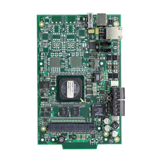
Connections Installation 2.3 Connections 2.3.1 Board Layout USB “B” Device (J1) USB “A” Host (J2) Ethernet Connector (J3) NUP A Connector (J4) Mounting Hole (1 of 12) Not Used (J5) Not Used (TB1) 24 V Out (TB2) 24 V In Figure 2.5 NFN-GW-EM-3 Connections Table 2.1 Connection Specifications Reference... - Page 18 Installation Connections (J1) (J3) LEDs (See Table Below) (J4) (J5) (TB1) (TB2) Figure 2.6 NFN-GW-EM-3 LEDs Table 2.2 LED Definitions Reference Label Description Designator ACTIVE Active/Lit indicates that WinCE is running. NUPA RX Blinks when data is received on the NUP A port (J4). PROGRAM Not Used NUPB RX...
-
Page 19: 2: Connecting To A Standard Ncm
Connections Installation 2.3.2 Connecting to a Standard NCM Connect Either Cable to Either NUP Connector on the NCM Communication from NUP A (J4) Only NFN-GW-EM-3 Out to NCM – 24V In From External Power Source to TB2 – 24 VDC Figure 2.7 Routing Power and Communication to a Standard NCM Table 2.3 Standard NCM Connections Type... -
Page 20: 3: Connecting To An Hs-Ncm
Installation Connections 2.3.3 Connecting to an HS-NCM For Communications, Connect USB A to B OR USB B to A HS-NCM NFN-GW-EM-3 Out to HS-NCM – – 24V In From External 24 VDC Power Source to TB2 Figure 2.8 Routing Power and Communication to an HS-NCM Table 2.4 HS-NCM Connections Type Connections... -
Page 21: 4: Connecting To A Fire Alarm Control Panel (Facp)
Connections Installation 2.3.4 Connecting to a Fire Alarm Control Panel (FACP) NUP Cable Provides Both Power and Communication From FACP To NUP “A” NUP Connector (J4) only NFN-GW-EM-3 FACP Not Used Figure 2.9 Connecting to an FACP via NUP Connector 2.3.5 Connecting to the PNET-1 Surge Suppressor Ground PNET-1... -
Page 22: System Power
Installation System Power 2.4 System Power Table 2.5 Power Requirements Power Requirement Input Voltage (Nominal) 24 VDC Input Current @ 24 VDC 125 mA 2.5 Testing and Maintenance Testing and maintenance should be performed according to the Testing and Maintenance section of NFPA-72 and CAN/ULC S561-03. -
Page 23: Section 3 Configuration
Section 3 Configuration 3.1 Configuration Web Page Configuration of the NFN-GW-EM-3 is via a web page running on the NFN-GW-EM-3. Supported web browsers are listed in 1.3, "Required Software". The following information applies to IP settings: • Each NFN-GW-EM-3 is shipped with a default IP address of 192.168.1.2 and a default node number of 240. -
Page 24: 2: Basic Configuration Tool Layout
Configuration Configuring the NFN-GW-EM-3 3.2.2 Basic Configuration Tool Layout Click to Select Click to Click for Product Main Menus (see 3.2.3) Select/Deselect Information (see 3.2.4) Click to Enter/Change Property/Value Pane Navigation Tree: Additional Properties (see 3.2.5) Click to View Sub-items Node List (see 3.2.6) Figure 3.1 Basic Configuration Tool Layout NFN-GW-EM-3 Installation and Operation Manual –... -
Page 25: 3: Main Menus
Configuring the NFN-GW-EM-3 Configuration 3.2.3 Main Menus The configuration main menus are located at the upper left-hand area of the screen (see Figure 3.1). Menu Sub-Menu Description File Reboot Reboots the NFN-GW-EM-3. View Node Table Displays a window containing software version information for all monitored nodes. -
Page 26: 5: Additional Properties
Configuration Configuring the NFN-GW-EM-3 3.2.5 Additional Properties The Additional Properties folder is located in the navigation tree area of the configuration tool (see Figure 3.1). Sub-Item Property Value Time Zone GMT Minute Offset - Click the value to set the offset (in minutes) to Greenwich Mean Time. Reference Settings Default is -300 (Eastern Standard Time). -
Page 27: 6: Node List
Configuring the NFN-GW-EM-3 Configuration Sub-Item Property Value Send Time to NFN Settings When the checkbox is selected, the NFN-GW-EM-3 will send the time to the NFN network. Panels (Cont’d) (Default is with box checked) Channel A Select High for a high-noise NFN network. Threshold Set to Low for a low-noise NFN network. -
Page 28: Security Certificate
Configuration Security Certificate 3.3 Security Certificate The NFN-GW-EM-3 communicates with the browser using secure communications. When connecting to the NFN-GW-EM-3, the browser may display a security warning. An example is shown in Figure 3.2. The NFN-GW-EM-3 includes a self-signed security certificate which causes the browser to display the warning. The self-signed security allows the encrypted connection between the NFN-GW-EM-3 and the browser. -
Page 29: Appendix A: Gateway Settings
Appendix A: Gateway Settings NOTE: The procedures in this Appendix require the use of a USB flash memory drive. A.1 Viewing Existing IP Settings 1. Connect the flash drive to the NFN-GW-EM-3. 2. Reboot the gateway. A file is created that matches the configured IP address of the gateway, followed by the extension “.txt”... - Page 30 NFN-GW-EM-3 Installation and Operation Manual – P/N LS10017-000NF-E:C3 6/5/2014...
- Page 31 Manufacturer Warranties and Limitation of Liability Manufacturer Warranties. Subject to the limitations set forth herein, Manufacturer warrants that the Products manufactured by it in its Northford, Connecticut facility and sold by it to its authorized Distributors shall be free, under normal use and service, from defects in material and workmanship for a period of thirty six months (36) months from the date of manufacture (effective Jan.
- Page 32 World Headquarters 12 Clintonville Road Northford, CT 06472-1610 USA 203-484-7161 fax 203-484-7118 www.notifier.com...