Table of Contents
Advertisement
Quick Links
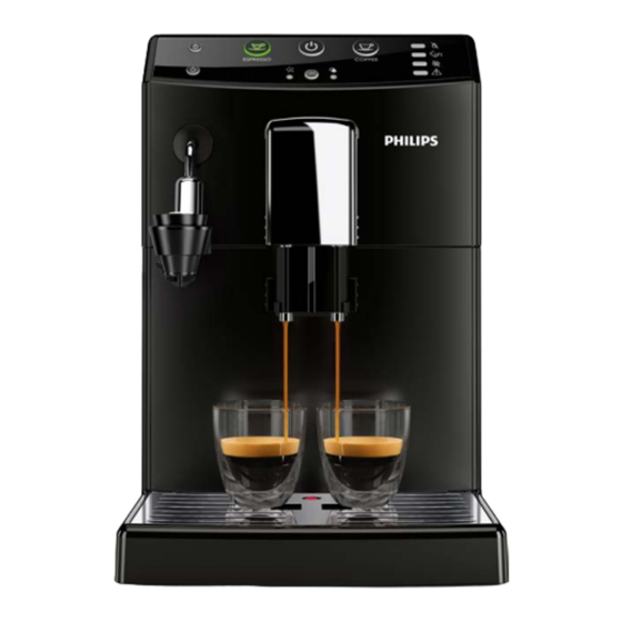
Coffee Machine
Service
General Information
Description
Housing material
Size (w x h x d)
Weight
Power Cord length
Control panel
Cup size
Water tank
Coffee bean hopper capacity
Coffee grounds drawer capacity
Pump pressure
Boiler
Safety devices
All parts of this document are the property of Philips.
All rights reserved. This document and all the information herein is provided without liability deriving from any errors or omissions. Furthermore, no part may be reproduced, used or
collected, except where express authorisation has been provided in writing or through a contractual agreement.
Published by Philips
Service Manual
Value
Thermoplastic material
215mm x 330mm x 429 mm
6.7 kg for CMF-AMF 7.5 Kg for OTC (data may vary depending on the model)
0.8m -1.2m
Front panel
Up to 152 mm
1.8 litres - Removable type
250 g
15
15 bar
Stainless steel type
Thermal fuse
Subject to modification
Philips 4000 and 3000
Rev. 25 JULY 2016
EN 4219 400 00027
2015-August-06
Advertisement
Table of Contents

Related Manuals for Philips 4000


Summary of Contents for Philips 4000
- Page 1 Thermal fuse All parts of this document are the property of Philips. All rights reserved. This document and all the information herein is provided without liability deriving from any errors or omissions. Furthermore, no part may be reproduced, used or collected, except where express authorisation has been provided in writing or through a contractual agreement.
-
Page 2: Table Of Contents
Machine parameters and performance 7.4. Coffee grinder adjustment 7.5. Carafe connection and hot/Steam water dispenser Brief instructions 3.1. Customer menu in the Philips 4000 OTC 7.6. Central plate 3.2. Customer menu in the Philips 4000 AMF 7.7. Pin boiler 3.3. - Page 3 PHILIPS 4000 and 3000 CHAPTER 1 INTRODUCTION...
-
Page 4: Introduction
PHILIPS 4000 and 3000 01 INTRODUCTION Documentation required The following documentation is needed for repair procedures: • Instruction booklet for specific model • Technical documentation for specific model (diagrams, exploded view, sympton cure and service manual) Tools and equipment required As well as the standard equipment, the following is required: Qty. Description Notes Screwdriver Pliers for Oetiker clamps CC -A - Vdc tester Digital thermometer Scale limit >... - Page 5 PHILIPS 4000 and 3000 01 INTRODUCTION Simply turning off the main machine power switch is not an adequate safety precaution. This domestic appliance is rated as insulation class I. On completion of the repair work, insulation and dielectric rigidity tests must be performed. Disassembling the machine, the operator must pay attention to hot and under Pressure parts: boiler, pin-boiler, valves, dispensing, steam tube, brew unit, connections and pipes to avoid burns. Please refer to specific hydraulic circuit (Image1) to know the parts in detail.
-
Page 6: Service Policy
PHILIPS 4000 and 3000 01 INTRODUCTION Service POLICY grid as used for coffee machine For IN WARRANTY repairs is raccomanded to use when and where possible the single compo- nents, available in the exploded views of the coffee machines or of the specific components. If you find the information “SEE THE EXPLODED VIEW E..” in the assembly description field, it means that the single components of the assembly are available in the other pages of the exploded view. -
Page 7: External Machine Parts Philips 4000
PHILIPS 4000 and 3000 01 INTRODUCTION 1.6.1. External machine parts Philip 4000 Automatic Milk Frother (also for steam dispensing) (AMF) Classic Milk Frother (also for wa- ter/steam dispensing) (CMF) Pre-ground coffee Water tank Espresso/Coffee compartment selection level Coffee bean (OTC) -
Page 8: External Machine Parts Philips 3000
PHILIPS 4000 and 3000 01 INTRODUCTION 1.6.2. External machine parts Philip 3000 Automatic Milk Frother (also for steam dispensing) (AMF) Water tank Pre-ground coffee compartment Coffee bean hopper with lid Classic Milk Frother (also for water/steam dispensing) (CMF) Coffee dispenser... -
Page 9: Internal Machine Parts
PHILIPS 4000 and 3000 01 INTRODUCTION 1.6.3 Internal machine parts Power board Pump Thermostat Boiler Flow-meter Grinding adjustment insert Coffee grinder Safety valve 2-way solenoid valve Coffee dispenser Boiler pin... -
Page 10: Technical Specifications
PHILIPS 4000 and 3000 CHAPTER 2 TECHNICAL SPECIFICATIONS... -
Page 11: Technical Specifications
PHILIPS 4000 and 3000 02 TECHNICAL SPECIFICATIONS 2.1. Technical specifications Power supply and output: 240 V~ 50 Hz 1850 W - 230 V~ 50/60 Hz 1850 W 120 V~ 60 Hz 1500 W Temperature monitoring: (NTC) variable resistor sensor - transmits the value to the... -
Page 12: Specification For The Measurement Of The Coffee Products
PHILIPS 4000 and 3000 02 TECHNICAL SPECIFICATIONS 2.2.1. Specification for the measurement of the coffee products temperature. The temperature is influenced by the flow from the dispenser and stratification of temperatures in the glass. In order to consider these phenomena and to introduce measures that allow comparisons in controlled conditions, below guidelines must be followed: Conditions: a) Water temperature in tank: 23°C (+/-2°C). b) It must be used a plastic cup (see picture N°1). -
Page 13: Specification For The Measurement Of The Milk Products
PHILIPS 4000 and 3000 02 TECHNICAL SPECIFICATIONS 2.2.2. Specification for the measurement of the Milk products temperature. Milk evaluation To carry out the test, a partially skimmed UHT milk with a percentage of grease between 1.5-1.8% at a refrigerator temperature Trefr. (between 4 to 10°C) must be used. The milk product must be checked on a beaker of 250 ml of capability and with an inner diameter of 70mm, brewing 100gr of product. - Page 14 PHILIPS 4000 and 3000 02 TECHNICAL SPECIFICATIONS How to measure the milk cream. The temperature (Trefr or Tamb) of the milk doesn’t affect as much the test result on measuring the milk cream; by convection is assumed to always use milk at refrigerator temperature Trefr..
-
Page 15: Machine Parameters And Performance
PHILIPS 4000 and 3000 02 TECHNICAL SPECIFICATIONS 2.3. Machine parameters and performance Programm. by PRODUCT Default quantity User Production / QUANTITY (Grams) programmable Service Espresso 40 +/- 10gr Espresso lungo 120 +/- 10% Classic coffee Min.145 Max.190 Hot water Continues until the water supply has been exhausted (capacitive sensor) -
Page 16: Brief Instructions
PHILIPS 4000 and 3000 CHAPTER 3 BRIEF INSTRUCTIONS... -
Page 17: Customer Menu In The Philips 4000 Otc
PHILIPS 4000 and 3000 03 BRIEF INSTRUCTIONS 3.1. Customer menu in the Philips 4000 OTC Espresso Classic coffee brew button brew button Long espresso “Aroma” Pre-ground brew button coffee button ON/OFF button Cappuccino MENU button brew button This machine is equipped with a colour-coded system to make your understanding of the display signals easier. - Page 18 PHILIPS 4000 and 3000 03 BRIEF INSTRUCTIONS The machine is programming the amount of milk to be dispensed for a cappuccino. The machine reminds you to The machine is programming insert the carafe and remove the amount of coffee to be the dispensing spout.
-
Page 19: Customer Menu In The Philips 4000 Amf
The machine is out of order. The error code is displayed in the right bottom corner. For error codes 1 -3 - 4 - 5, please refer to the “Troubleshooting” chapter. For any other error codes, follow the instructions below: Turn off the machine. Turn it back on after 30 seconds. Try this 2 or 3 times. 3.2. Customer menu in the Philips 4000 AMF Espresso Classic coffee brew button brew button “Aroma”... - Page 20 PHILIPS 4000 and 3000 03 BRIEF INSTRUCTIONS Espresso brewing using pre- The machine is programming the ground coffee in progress. amount of espresso to be brewed. The machine is programming the Long espresso brewing using amount of long espresso to be pre-ground coffee in progress.
- Page 21 PHILIPS 4000 and 3000 03 BRIEF INSTRUCTIONS 3.3. Customer menu in the Philips 4000 AMF Classic coffee Espresso brew button brew button Long espresso “Aroma” Pre-ground brew button coffee button ON/OFF button Hot water/steam MENU button button Ready Signals (Green Colour) The machine is brewing one cup of classic coffee.
- Page 22 PHILIPS 4000 and 3000 03 BRIEF INSTRUCTIONS Warning Signals (Yellow Colour) The brew group is being The machine is warming up. reset due to machine reset. The machine is performing the Fill the coffee bean hopper with rinse cycle. Wait until the machine coffee beans and restart the has completed the cycle.
-
Page 23: Customer Menu In The Philips 3000 Amf
PHILIPS 4000 and 3000 03 BRIEF INSTRUCTIONS 3.4. Customer menu in the Philips 3000 AMF Coffee brew button Espresso ON/OFF button brew button No water light Cappuccino Empty coffee grounds button drawer light No coffee light Hot water button General warning light... - Page 24 PHILIPS 4000 and 3000 03 BRIEF INSTRUCTIONS The machine is brewing two cups of coffee. Quick double flashing The machine is programming the amount of espresso to be brewed. Flashing quickly The machine is programming the amount of coffee to be brewed. Flashing quickly The machine is in the steam dispensing phase.
-
Page 25: Customer Menu In The Philips 3000 Cmf
Steady on Your machine is out of order. Turn off the machine. Turn it back on after 30 seconds. Repeat the procedure 2 or 3 times. If the machine does not start, contact the Philips hotline in your country (contact details in the warranty booklet). All lights flashing simultaneously 3.5. Customer menu in the Philips 3000 CMF... - Page 26 PHILIPS 4000 and 3000 03 BRIEF INSTRUCTIONS Warning Signals The machine is performing one of the following operations: - Warm-up - Automatic rinse. Flashing The machine needs to prime the circuit. Press the “ ” button. Once pressed, the button turns off . The “ ” and ” “ lights flash while the circuit is being primed, and they turn off once priming has been completed. “ ” steady on “ ” and “ ” flashing The machine is ready for product brewing.
- Page 27 PHILIPS 4000 and 3000 03 BRIEF INSTRUCTIONS The machine is programming the amount of coffee to be brewed. Flashing quickly The machine is in the steam dispensing phase. Flashing slowly The machine is in the hot water dispensing phase. Flashing slowly Fill the water tank.
- Page 28 PHILIPS 4000 and 3000 03 BRIEF INSTRUCTIONS The coffee grounds drawer is not inserted into the machine. Wait a few seconds until the “ ” light turns off and the “ ” light shines steadily. Then insert the coffee grounds drawer and close the service door.
-
Page 29: Operation, Cleaning And Maintenance
PHILIPS 4000 and 3000 03 BRIEF INSTRUCTIONS 3.6. Operation, cleaning and maintenance Operating the machine Fill water tank Fill the coffee bean hopper Switch on the appliance Press the button to start the appliance Heating When the heating phase begins, wait for it to finish Rinse Carry out a rinse cycle for the internal circuits... -
Page 30: Operating Logic
PHILIPS 4000 and 3000 CHAPTER 4 OPERATING LOGIC... -
Page 31: Water Circuit Philips 4000-3000
PHILIPS 4000 and 3000 04 OPERATING LOGIC 4.1. Water circuit Philips 4000 - 3000 1/10... -
Page 32: Milk Carafe
PHILIPS 4000 and 3000 04 OPERATING LOGIC 4.2. Milk Carafe 4000 OTC 1) Steam input 2)Bring the cappuccino maker into dispensing position 3) Milk tank The milk is heated by the steam and taken towards the emulsion chamber Steam where it is mixed with air and transformed into foam The steam passes... -
Page 33: Single Microswitch
PHILIPS 4000 and 3000 04 OPERATING LOGIC 4.3. Single microswitch Switching on When the machine is switched on, the gear motor repositions itself as follows: - It acts on microswitch 1 - The gear motor changes its rotation direction and moves upwards again by approx. 1-2 mm. - T he boiler begins to heat the water for approx. 45 sec., at full power, in order to reach the optimal temperature. The temperature will then remain at a constant level. -
Page 34: Coffee Grinder Philips 4000
PHILIPS 4000 and 3000 04 OPERATING LOGIC 4.4. Coffee grinder Philips 4000 The coffee grinder is driven by a direct current motor (1) using a worm screw helicoidal wheel transmission (2). The worm screw (2) drives a plastic gear wheel (3), which turns the lower grinder (4) and the increment pin (5) 4.4.1 Autodose system description Aroma 4/5... -
Page 35: Coffee Lack Detection An Coffee Grinder Blocked
PHILIPS 4000 and 3000 04 OPERATING LOGIC 1) When the system get the stability (i.e. the system got the current target) the coffee doses should be: A2/3 A4/5 7,5 9,0 10 ±1,5 grams with medium grinding (500±60μm) and using coffee of test. 2) the 3 grinding times are always: <T <T beside, every grinding time is, respectively: 4,0s ≤T... -
Page 36: Coffee Cycle
PHILIPS 4000 and 3000 04 OPERATING LOGIC 4.5. Coffee cycle Main switch ON START STOP Time Coffee grinder Time (Dosage) Heating approx. 45 sec. Pump Pump operation (flow meter pulses) in accordance with the amount of product selected. Brewing unit gear motor... -
Page 37: Coffee Grinder Philips 3000 And 120V
PHILIPS 4000 and 3000 04 OPERATING LOGIC 4.5.1. Coffee grinder Philips 3000 and 120V The coffee grinder is driven by a direct current motor (1) using a worm screw helicoidal wheel transmission (2). The worm screw (2) drives a plastic gear wheel (3), which turns the lower grinder (4) and the increment pin (5) There are two magnets (6) in the gear wheel; at every rotation these induce two pulses to a Hall sensor, which in turn transmits them to the electronic system. -
Page 38: Dose Self-Learning (Sas)
PHILIPS 4000 and 3000 04 OPERATING LOGIC 4.5.3. Dose self-learning (SAS) The aim of this function is to automatically regulate the average dose of ground coffee (SELF- LEARNING); this takes place with an algorithm based on the following values and setting by the user: 1. -
Page 39: Water Level Detection (Water Tank)
PHILIPS 4000 and 3000 04 OPERATING LOGIC 4.6. Water level detection (water tank) “Water low” message (water reserve) Function: The water level is monitored by a capacitative sensor, located one Water tank third of the way up the water tank wall. If the electronics assembly detects, by means of the sensor, that the amount of water in the tank has dropped below the... -
Page 40: Water Filter
PHILIPS 4000 and 3000 04 OPERATING LOGIC 4.8. Water filter Function: • Reduced limescale deposits which take longer to form. • Improved water quality. • Improved taste due to the ideal water hardness. Life span / descaling performance: • - 10 ° dH • 60 litres... -
Page 41: Service Mode
PHILIPS 4000 and 3000 CHAPTER 5 SERVICE MODE... -
Page 42: Test Mode Philips 4000
PHILIPS 4000 and 3000 05 SERVICE MODE 5.1. Test Mode Philips 4000. Introduction This document describes the Test Mode of the Philips 4000 (CMF,AMF & OTC) Coffee Machine. This application is used in order to test the machine in its mechanics and electronic components. To enter Test Mode The machine enters in Test mode by holding pressed together Z1 and Z6 buttons while switching on the machine by the main switch on the backside of the CA. - Page 43 PHILIPS 4000 and 3000 05 SERVICE MODE Page 5: High voltage loads test (Heater , Grinder ): a) Heater (230V AC) b) Grinder (320V DC) The user can change the page by pressing the Z7 button. Page 0 is accessible only entering Test Mode from power-off mode; at the start up all loads are turned off.
- Page 44 PHILIPS 4000 and 3000 05 SERVICE MODE Page 1 (KEYBOARD) Start condition Press buttons from 1 to 7 Only when a button is pressed a O appears on the relative position of button pressed. In the middle of display appears the name of the button pressed.
- Page 45 PHILIPS 4000 and 3000 05 SERVICE MODE Insert a full Water Tank The indication H20 changes from “N” to “Y”. Note: the switching from “N” to “Y” requires about 1-2 seconds. ERROR: The indication TANK-H2O doesn’t change; check the capacitive sensor (fixing) and the wiring (JP23) Insert the BrewUnit The indications BU-P changes from “N” to “Y”.
- Page 46 PHILIPS 4000 and 3000 05 SERVICE MODE When the BU reaches the work position the indication WORK changes from “N” to “Y”, the number of the current is less than 200mA (without BU) or 300mA (with BU). ERROR: The indication WORK doesn’t change and remain “N”, the display backlight changes from green to red; Check the work microswitch (broken?), the BU motor (blocked?) and the wiring (JP16).
- Page 47 PHILIPS 4000 and 3000 05 SERVICE MODE The machine passes to the Page 4 (EV - PUMP) Page 4 (EV - PUMP) Start condition Press the Z1 button to open the Electro Valve IMPORTANT NOTE: If the DREGDRAWER is not inserted or the DOOR is not closed the EV test cannot be performed.
- Page 48 PHILIPS 4000 and 3000 05 SERVICE MODE Start condition Press the Z4 button to switch on the grinder. The grinder rotates and in the indication GRINDER the number increasing up to 5000 (5seconds test). The other numbers inside the GRINDER box are not important for this test.
-
Page 49: Steamout
PHILIPS 4000 and 3000 05 SERVICE MODE 5.1.1. SteamOut This document describes the Steam-Out procedure; the application is used in order to empty the heater. To enter in SteamOut The machine enters in Steam-Out mode by holding pressed together: the “ESPRESSO LUNGO” button and the MENU button;... - Page 50 PHILIPS 4000 and 3000 05 SERVICE MODE When the Steam-Out is complete the following parameters are reset to their default values: Length “Espresso” product (Default 128 impulses) Length “Espresso Lungo” product (Default 292 impulses) Length “Large Coffee” product (Default 428 impulses) Length “Cappuccino”...
-
Page 51: Test Mode Philips 3000
PHILIPS 4000 and 3000 05 SERVICE MODE 5.2. Test Mode Philips 3000 To enter Test Mode The machine enters in test mode by holding together Espresso and Calc-Clean button while switching on the machine by mean of the main switch on the backside of the CA. - Page 52 PHILIPS 4000 and 3000 05 SERVICE MODE The user can switch the level by pressing the Button Stand-By, the machine shows the level of the test: a) Level 1 : Led Espresso ON (G), Led Stand-by ON (R) b) Level 2 : Led Espresso ON (G), Led Descale ON (O) c) Level 3 : Led Espresso ON (G), Led Descale ON (O), Led Calc-Clean ON (O) d) Level 4 : Led Espresso ON (G), Led Descale ON (O), Led Calc-Clean ON (O),Led Rinsing ON (O) e) Level 5 : Led Espresso ON (G), Led Descale ON (O),Led Calc-Clean ON (O),Led Rinsing ON (O), Led Coffee ON (G). Legend: (O) = Orange (G) = Green (R) = Red TEST MODE Level0 Pressing button Stand-By TEST MODE Level1 Pressing button Stand-By...
- Page 53 PHILIPS 4000 and 3000 05 SERVICE MODE Press Espresso Button Action by user LED INDICATION Led Dreg NoBeans NoWater GenAlarm drawer full Descale Rinsing Switch on Red Leds NoWater & Dreg drawer full ERROR: Led NoWater remains off, check the interface board and flat cable (JP21) ERROR: Led Dreg drawer full remains off, check the interface board and flat cable (JP21) ERROR: Led NoWater & Dreg drawer full remain off, check the interface board and flat cable (JP21) Press CalcCLean Button Action by user...
- Page 54 PHILIPS 4000 and 3000 05 SERVICE MODE Press Hot Water Button Action by user LED INDICATION Led Steam Button Led Hot-Water Button Switch on green Led under the Hot Water button ERROR: Led Hot-Water remains off, check the interface board and flat cable (JP21) Finish condition: NO BU, NO drag drawer, LED INDICATION door open and No Water sensor...
- Page 55 PHILIPS 4000 and 3000 05 SERVICE MODE Press BUTTON Stand-By to move to the next screen Level 3 (Brewing unit) Start condition: NO BU, Drag drawer, door LED INDICATION Closed and No Water sensor Led Dreg NoBeans NoWater GenAlarm drawer full If the Dreg drawer is not inserted or the Service door is not closed the BU test cannot be performed.
- Page 56 PHILIPS 4000 and 3000 05 SERVICE MODE Press the Espresso button to open the EV Action by user LED INDICATION Led Dreg NoBeans NoWater GenAlarm drawer full It is possible to hear the “click” from ElectroValve. The Led NoBeans is switched on...
- Page 57 PHILIPS 4000 and 3000 05 SERVICE MODE Press the Espresso button to switch on the Heater Action by user LED INDICATION Led Dreg NoBeans NoWater GenAlarm drawer full The user checkers that the absorbed current is OK ERROR: the absorbed current is KO; check the wiring...
-
Page 58: Steamout
PHILIPS 4000 and 3000 05 SERVICE MODE 5.2.1. SteamOut To enter in SteamOut The machine enters SteamOut mode by holding pressed together the COFFEE button and the CALC_CLEAN button while switching on the machine. Once entered the machine shows Led Descale and Led Rinsing flashing in series. -
Page 59: Error Codes
PHILIPS 4000 and 3000 05 SERVICE MODE 5.3. Error codes ERROR DESCRIPTION CODES The coffee grinder is blocked (grinder blades jammed or sensor not reading properly) The grinder is disconnected (Only coffee grinder without electronic sen- sor) The brewing unit is blocked in work position (microswitch not released in up position after 3", torque error trying to move down, descent time... -
Page 60: Service And Maintenance
PHILIPS 4000 and 3000 CHAPTER 6 SERVICE AND MAINTENANCE... -
Page 61: Repair Flow
Repair Flow PHILIPS 4000 and 3000 06 SERVICE AND MAINTENANCE 6.1. Repair Flow Proces stap Saeco no. Action Intake 1 Visual inspection (transport damage) take care for pictures Check Type/serialnumber 2 Log all available accessory ... - Page 62 Grinder Is the grinder noise normal Steam Steam Does the steam work Hot Water Does the hot water work PHILIPS 4000 and 3000 06 SERVICE AND MAINTENANCE Milk (if applicable) Cappuchino Does the cappuccinatore produce good froth Leakage Leakage 14 Did the product leak during the testing ...
-
Page 63: Disassembly
PHILIPS 4000 and 3000 CHAPTER 7 DISASSEMBLY... -
Page 64: Outer Shell
PHILIPS 4000 and 3000 07 DISASSEMBLY 7.1. Outer Shell Philips 3000 Remove the water tank, coffee container cover, drip tray, dreg drawer, brewing unit. Coffee dispenser 4000 Remove the dispenser cover leveraging the grooves Unscrew the screws shown and remove the lever Remove the dispenser Unscrew the screw shown and remove... -
Page 65: Coffee Grinder
PHILIPS 4000 and 3000 07 DISASSEMBLY exploded view of the 3000 4000 coffee dispenser Upper cover Unscrew the screws shown, raise the top cover and remove the electrical and water circuit con- nections. 7.2. Coffee grinder When reassembling the coffee Raise the coffee grinder and remove the connections. grinder, make sure the spring is repositioned correctly (see photo). The new machines have a coffee grinder with the screw to prevent the disassembly of the upper coffee grinder support (see photo). -
Page 66: Grinder Blades
PHILIPS 4000 and 3000 07 DISASSEMBLY 7.3. Grinder blades Caution in the new coffee grinder with the screw, Unscrew this last, before disassembly of the upper coffee grinder sup- port. To extract the top support of the appliance, press on the grinding adjustment spindle (A) and turn the support anti- clockwise until it unhooks. Turn the grinder blades anticlockwise out of the support. Turn the grinder blades clockwise out of the support. The bayonet connections can be accessed from the rear. -
Page 67: Coffee Grinder Adjustment
PHILIPS 4000 and 3000 07 DISASSEMBLY 7.4. Coffee grinder adjustment The grinding adjustment can be set by the user (only with the cof- fee grinder in operation) by pressing and turning (only by one click at a time) the insert inside the coffee bean hopper with the aid of the wrench supplied. -
Page 68: Central Plate
PHILIPS 4000 and 3000 07 DISASSEMBLY hot water dispenser unscrew the screws Removes the covers shown shown 7.6. Central plate unscrew the screws shown Lift up the center plate 7.7. Pin boiler Loosen the screws as illustrated and remove the boiler pin (A). -
Page 69: Gear Motor
PHILIPS 4000 and 3000 07 DISASSEMBLY 7.8. Gear motor Loosen the screws as illustrated and remove the gear motor cover. The following are located inside the compartment protected by the casing: - Electric motor (A) with gears (B) and (C) for transmission and timing of the dispenser. -
Page 70: Pump
PHILIPS 4000 and 3000 07 DISASSEMBLY 7.9. Pump Unhook the pump Disconnect the water circuit connections (A) and from the supports. electrical connections (B), loosen the safety valve (C) and slide the pump off the brackets (D). 7.10. Flow-meter Lift the flow meter out of the casing assembly and remove the electrical and water circuit connections. 7.11. Boiler Unscrew the screw shown and remove the electrical and water circuit connections. -
Page 71: Cpu Board
PHILIPS 4000 and 3000 07 DISASSEMBLY 7.12. CPU board Loosen the screws slide the card off the support and disconnect the electrical connections. 7.13. Programming access for SSC (Saeco Service Center) Loosen the screw for remove the cover. 7.14. KYB interface and display Remove the cover. -
Page 72: Fitting And Removing Oetiker Clamps
PHILIPS 4000 and 3000 07 DISASSEMBLY 7.15. Fitting and removing Oetiker clamps 1) Boiler connection. 2) Other connections. Use a suitable pair of pliers to remove the Tighten the clamp as illustrated. clamp (as illustrated). -
Page 73: Notes
PHILIPS 4000 and 3000 CHAPTER 8 NOTES... - Page 74 PHILIPS 4000 and 3000 08 NOTES...
-
Page 75: Water Circuit Diagram
PHILIPS 4000 and 3000 CHAPTER 9 WATER CIRCUIT DIAGRAM... - Page 76 PHILIPS 4000 and 3000 09 WATER CIRCUIT DIAGRAM Philips 4000/3000...
-
Page 77: Electrical Diagram
PHILIPS 4000 and 3000 CHAPTER 10 ELECTRICAL DIAGRAM... - Page 78 PHILIPS 4000 and 3000 10 ELECTRICAL DIAGRAM Philips 4000...
- Page 79 PHILIPS 4000 and 3000 10 ELECTRICAL DIAGRAM Philips 3000...