Makita LS1019L Instruction Manual
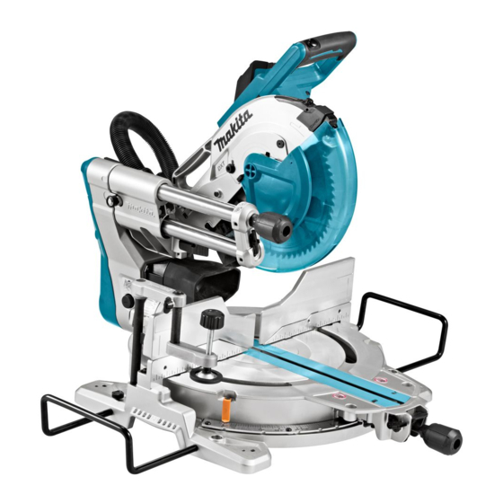
Slide compound miter saw
Hide thumbs
Also See for LS1019L:
- Instruction manual (181 pages) ,
- Instruction manual (141 pages) ,
- Instruction manual (92 pages)

Related Manuals for Makita LS1019L


Summary of Contents for Makita LS1019L
- Page 1 INSTRUCTION MANUAL Slide Compound Miter Saw LS1019 LS1019L DOUBLE INSULATION Read before use.
-
Page 2: Specifications
SPECIFICATIONS Model: LS1019 LS1019L Blade diameter European countries 260 mm Countries other than Europe 255 mm - 260 mm Hole diameter European countries 30 mm Countries other than Europe 25.4 mm Max. kerf thickness of the saw blade 3.2 mm Max. -
Page 3: Power Supply
) : 101 dB (A) The term "power tool" in the warnings refers to your Uncertainty (K) : 3 dB(A) mains-operated (corded) power tool or battery-operated Model LS1019L (cordless) power tool. Sound pressure level (L ) : 91 dB(A) Work area safety... -
Page 4: Safety Instructions For Mitre Saws
Use personal protective equipment. Always wear eye Service protection. Protective equipment such as a dust mask, Have your power tool serviced by a qualified repair non-skid safety shoes, hard hat or hearing protection used person using only identical replacement parts. This will for appropriate conditions will reduce personal injuries. - Page 5 Inspect your workpiece before cutting. If the 19. Hold the handle firmly when making an incom- workpiece is bowed or warped, clamp it with plete cut or when releasing the switch before the outside bowed face toward the fence. the saw head is completely in the down posi- Always make certain that there is no gap tion.
-
Page 6: Parts Description
14. Make sure that the turn base is properly 21. Do not attempt to lock the trigger in the "ON" position. secured so it will not move during operation. 22. Always use accessories recommended in this Use the holes in the base to fasten the saw to a manual. -
Page 7: Installation
Switch trigger Lock-off button Hole for padlock Switch (for laser line) Hose (for dust Stopper pin (for carriage Guide fence (lower Guide fence (upper extraction) elevation) fence) fence) Dust bag 0° adjusting bolt (for Bevel angle scale Releasing lever (for 48° bevel angle) bevel angle) Latch lever (for bevel Pointer (for bevel angle) -
Page 8: Bench Mounting
When cleaning is complete, reverse procedure above and secure bolt. Do not remove spring holding blade guard. If guard becomes discolored through age or UV light exposure, contact a Makita service center for a new guard. DO NOT DEFEAT OR REMOVE GUARD. 8 ENGLISH... - Page 9 ► 1 . Left bevel cut 2. Straight cut 3. Right bevel cut 4. Saw blade 5. Blade teeth 6. Kerf board First, unplug the tool. Loosen all the screws (2 each on left and right) securing the kerf boards until the kerf boards can still be easily moved by hand.
-
Page 10: Adjusting The Miter Angle
Adjust the blade position by turning the adjusting bolt WARNING: After installing a new blade and with the hex wrench. The periphery of the blade should with the tool unplugged, always be sure that the extend slightly below the top surface of the turn base blade does not contact any part of the lower base and also comes to the point where the front face of the when the handle is lowered completely. -
Page 11: Adjusting The Bevel Angle
Pull and turn the latch lever to the position as illustrated. ► 1 . Latch lever ► 1 . Lock lever 2. Grip 3. Releasing lever 4. Pointer Match the pointer with your desired angle on the scale by moving the carriage then tighten the knob. Rotate the grip counterclockwise to unlock the turn base. -
Page 12: Slide Lock
NEVER use the tool if it runs when you simply pull the switch trigger without press- ing the lock-off button. A switch in need of repair may result in unintentional operation and serious personal injury. Return tool to a Makita service center for proper repairs BEFORE further usage. ► 1 . Latch lever CAUTION: After changing the bevel angle, always secure the knob. -
Page 13: Electronic Function
Soft start feature This function allows the smooth start-up of the tool by limiting the start-up torque. Laser beam action For model LS1019L only CAUTION: Never look into the laser beam. Direct laser beam may injure your eyes. To turn on the laser beam, press the upper position (I) of the switch. -
Page 14: Removing The Blade
Accidental start up of the tool may result in serious personal injury. WARNING: Use only the Makita wrench provided to install or remove the blade. Failure to use the wrench may result in overtightening or insufficient tightening of the hex socket bolt and serious personal injury. ► 1 . Center cover 2. Hex wrench 3. Blade guard... -
Page 15: Installing The Blade
When you wish to perform clean cutting operation, con- the direction of the arrow on the surface of the blade matches nect a Makita vacuum cleaner to the dust nozzle using the direction of the arrow on the blade case. -
Page 16: Securing Workpiece
Guide fences WARNING: Before operating the tool, make sure that the upper fence is secured firmly. WARNING: Before bevel-cutting, make sure that no part of the tool, especially the blade, contacts the upper and lower fences when fully lowering and raising the handle in any position and while moving the carriage through its full range of travel. - Page 17 The horizontal vise can be installed in two positions on Vertical vise either the left or right side of the base. When performing 22.5° or greater miter cuts, install the horizontal vise on WARNING: the side opposite the direction in which the turn base is The workpiece must be secured to be turned.
-
Page 18: Operation
Push the carriage toward the guide fence until it OPERATION stops and lock it with the stopper pin. Secure the workpiece with the proper type of vise. WARNING: Make sure the blade is not contacting Switch on the tool without the blade making any contact the workpiece, etc. -
Page 19: Miter Cutting
Switch on the tool without the blade making any Remove the upper fence on the side that you are contact and wait until the blade attains full speed. going to tilt the carriage. Press the handle down and push the carriage Unlock the stopper pin. - Page 20 In the case of left bevel cut (a) (b) (c) (d) (a) (b) (c) (d) ► 1 . Inside corner 2. Outside corner ► 1 . Inside corner 2. Outside corner Table (A) – Molding Bevel angle Miter angle position 52/38°...
- Page 21 In the case of right bevel cut At right 45° miter angle (a) (b) (c) (d) ► 1 . Crown molding stopper L 2. Crown molding stop- ► 1 . Inside corner 2. Outside corner per R 3. Turn base 4. Guide fence Table (A) At left 45°...
-
Page 22: Groove Cutting
Groove cutting WARNING: Do not attempt to perform this type of cut by using a wider type blade or dado blade. Attempting to make a groove cut with a wider blade or dado blade could lead to unexpected cutting results and kickback which may result in serious personal injury. -
Page 23: Maintenance
► 1 . Screw on pointer 2. Screws on miter angle scale 3. Miter scale WARNING: Stopper pin for carriage elevation Set the turn base to the 0° position using the positive is for carrying and storage purposes only and not stop function. - Page 24 Align the pointer with 0° position in the bevel angle scale and then tighten the screw. Adjusting the laser line position 45° bevel angle NOTICE: For model LS1019L only Before adjusting the 45° bevel angle, finish 0° bevel angle adjustment. WARNING: The tool must be plugged in while Loosen the knob and fully tilt the carriage to the side adjusting the laser line.
- Page 25 NOTICE: Have the tool repaired by a Makita authorized service center for any failure on the laser unit. The movable range of laser line is decided by the range adjustment screws on both sides. Perform following...
-
Page 26: Replacing Carbon Brushes
OPTIONAL ACCESSORIES WARNING: These Makita accessories or attachments are recommended for use with your Makita tool specified in this manual. The use of any other accessories or attachments may result in serious personal injury. ► 1 . Limit mark WARNING: Only use the Makita accessory Remove and check the carbon brushes regularly. - Page 28 Makita Europe N.V. Jan-Baptist Vinkstraat 2, 3070 Kortenberg, Belgium Makita Corporation 3-11-8, Sumiyoshi-cho, Anjo, Aichi 446-8502 Japan 885575A224 www.makita.com 20170119...