
Related Manuals for XtendLan DPC-D244-R


Summary of Contents for XtendLan DPC-D244-R
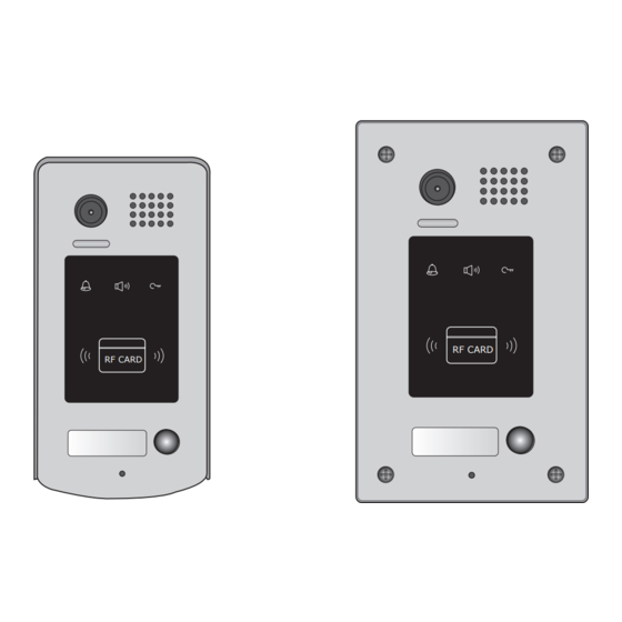
- Page 1 2 -Wire Intercom System DPC-D244-R DPC-D244-FR User's manual RF CARD RF CARD DPC-D244-R DPC-D244-FR...
-
Page 2: Parts And Functions
1.Parts and Functions Camera Lens Speaker Indicator ID card window RF CARD RF CARD 28 mm Nameplate Call Button Microphone Rainy Cover DT596/ID 90 mm Camera Lens Speaker Indicator ID card window RF CARD RF CARD Nameplate Call Button Screws for panel mounting Microphone Mounting box... -
Page 3: Door Station Mounting
• • S1+,•S2+:•Lock•power(+)•output,•to•connect•2•locks. • • S-:•Lock•power(-)•output,•connect•to•the•power(-)•input•of•locks(only•when•using•the•camera•to•power• the•locks,•if•using•the•external•power•supply•for•the•locks,•the•S-•will•not•be•connected). 3.Door Station Mounting DPC-D244-R Mounting adjust camera angle Drill holes in the wall to match the size of Connect the cable correctly and adjust screws and attach the rainy cover to the wall. -
Page 4: Adjusting Camera Angle
DPC-D244-FR Mounting adjust camera angle Drill a hole in the wall to match the size of the Connect the cable correctly and adjust mounting box and attach to the wall. right angle for camera Attach the panel to the mounting box and Place name label use screws supplied to fix the panel Adjusting Camera Angle... -
Page 5: Placing Name Label
Placing Name Label Press•the•plastic•cover•on•right/left•side•to•move•away•the•cover,insert•a•name•paper,then•put•the•plastic• cover•back•to•the•panel. RF CARD 4. System Wiring and Electric Lock Connection Basic Connection monitor L1 L2 PL S1+ S2+ S-... -
Page 6: Electric Lock Connection
Electric Lock Connection Door Lock Controlled with Internal Power •••••Note: 1.• Electronic•lock•of•Power-on-to-unlock•type•should•be•used. 2.• The•door•lock•is•limited•to•12V,•and•holding•current•must•be•less•than•250mA. 3.• The•door•lock•control•is•not•timed•from•Exit•Button(EB). 4.• The•Unlock Mode•Parameter•of•Monitor•must•be•set•to•0•(by•default). 1 2 3 1 2 3 Connect one lock Connect two locks Jumper position in Jumper position in LOCK LOCK LOCK Door Lock Controlled with Dry Contact •••••Note: 1.•... -
Page 7: Unlock Parameter Setting(Set On Monitor)
connect•one•lock connect•two•locks Take off the Jumper Take off the Jumper POWER POWER SUPPLY SUPPLY LOCK LOCK LOCK Unlock parameter setting(set on monitor) H/W : DT14-CT a1.3 S/W: V17.11.418.00 Manual Monitor Intercom Multimedia Monitor Local addr: Unlock timing: Video standard: Close UI-CODE: Memory Album... -
Page 8: Multi Door Stations Connection
Multi Door Stations Connection monitors DBC4 A B C D 85~260VAC 4# Camera 3# Camera 2# Camera 1# Camera ID=11 ID=01 ID=10 ID=00 1 2 3 4 1 2 3 4 1 2 3 4 1 2 3 4 L1 L2 PL S1+ S2+ S- L1 L2 PL S1+ S2+ S- L1 L2 PL S1+ S2+ S- L1 L2 PL S1+ S2+ S-... -
Page 9: Multi Monitors Connection
Multi Monitors Connection Basic IN-OUT Wiring Mode monitor 3 4 5 6 Code=15, DIP-6=on monitor 3 4 5 6 Code=14, DIP-6=off monitor 3 4 5 6 Code=0, DIP-6=off 85~260AC ID=00 RF CARD 1 2 3 4... -
Page 10: Dip Switches Settings Of Door Station
5.DIP Switches Setting ON(1) OFF(0) DIP Switches Settings of Door Station Total•4•bits•on•the•DIP•switches•can•be•configured.The•switches•can•be•modified•either•before•or•after• installation. Setting Item Bit state Descriptions Default•setting,•ID•=•0(00),•set•to•the•first•Door•Station. 1 2 34 ID•=•1(10),•set•to•the•second•Door•Station. Bit1•and•Bit2 1 2 34 (it•is•used•to•set•the•ID• code•for•door•station) ID•=•2(01),•set•to•the•third•Door•Station. 1 2 34 ID•=•3(11),•set•to•the•fourth•Door•Station. 1 2 34 The•relay•2•doesn't•respond•the•second•lock,showing•user• cards•controlled•two•locks•or•pressing•unlock•2nd•on•monitor• can• not• release• the• second• lock.During• this• time,After• continuously•showing•access•card•10•times,the•relay•2•will•be•... - Page 11 Bit-6•is•used•to•match•the•video•impendance,•which•have•to•be•set•to•on•if•the•monitor•is•in•the•end•of•the• bus,•otherwise•set•to•off.• Bit state Setting Bit state Setting The•monitor• The•monitor•is•• is•at•the•end• not•at•the•end• of•the•bus. 1 2 3 4 5 1 2 3 4 5 of•the•bus. Bit-1•to•Bit-5•are•used•to•User•Code•setting.The• DPC-D244 •responds•to•0~15•. Bit state User Code Bit state User Code Bit state User Code Code=0 Code=6 Code=11 3 4 5...
-
Page 12: Add User Cards
Add User Cards: 1.Control one lock(the first lock) Show•the• Show•user•cards•to•be• Show•the•• MASTER CARD MASTER CARD •card•to•ID•card•window• added,•one•by•one.• ••card•to•exit.But•it•will• in•standby•mode. return•to•standby•mode•if•no• operation•within•15s. blue blue blue (on) (off) (blink) (off) (off) (off) beep+,beep beep+ beep,beep+ 2.Control two locks Show•the• Press•"CALL"•button. Show•the•• MASTER CARD MASTER CARD •card•to•ID•card•window•... -
Page 13: Unlock Operations
Authorize master cards: By•default,there•are•two•master•cards•marked• •and• •,but•you• MASTER CARD ADD MASTER CARD DELETE should•know•that•the•master•card•can•be•authorized•by•users•at•any•time.That•means•any•two•user•cards• can•be•authorized•to•master•cards,When•registered•new•master•cards,•the•old•master•cards•are•invalid• automatically. Continuously•set•DIP4• The•first•card•showed•is•the• The•second•card•showed•is• switch•status•to•"off"->"on"• •card,it the• • MASTER CARD ADD MASTER CARD DELETE ->"off">"on"->off"->"on"•in• will•return•to•standby•if•no• card,it•will•return•to•standby• sequence,must•finish•in•3s. operation•within•10s. if•no•operation•within•10s. blue blue blue (on) (on) (off) (on) beep+ beep+,beep... -
Page 14: Specifications
• • You•can•activate•the•electric•door•strike•by•pressing•the•request•to•exit•button•connected•to•the•unit.• Pressing•request•to•exit•button•1•releases•relay•1,•and•pressing•request•to•exit•button•2•releases•relay• 2.(The•unlock•function•will•work•when•the•request•to•exit•button•is•pushed,•even•while•the•proximity• access•is•forbidden. 1.•If•show•the•authorized•user•card,the•buzzer•will•sound•of•beep+,and•the•LED•indicator•will•light• 2.•If•show•the•unauthorized•user•card,the•buzzer•will•sound•of•beep,beep,beep. 8. Precaustions • • Please•clean•the•unit•with•soft•cotton•cloth,•don't•use•the•organic•impregnant•or•chemical•clean•agent.•If• necessary,•please•use•a•little•pure•water•or•dilute•soap•water•to•clean•the•dust. • • The•unit•is•weather•resistant.•However•do•not•spray•high•pressure•water•on•access•control•keypad• directly.•Excessive•moisture•may•cause•problems•with•the•unit. • • You•must•use•the•right•adaptor•which•is•supplied•by•the•manufacture•or•approved•by•the•manufacture.. • • Pay•attention•to•the•high•voltage•inside•the•products,•please•refer•service•only•to•a•trained•and•qualified• professional. 9. Specifications • • Power•Supply•:•• • • • DC•24V•(supplied•by•PS4-24V•or•PS5-24V); • • Power•Consumption:•• • • Standby•60mA;•Working•status•200mA;... -
Page 15: Cables Requirements
10. Cables Requirements The•maximum•distance•of•the•wiring•is•limited•in•the•DT•system.•Using•different•cables•may•also•affect•the• maximum•distance•which•the•system•can•reach.• The farest monitor monitor with two or four monitors monitor monitor DBC/DBC-4 When Monitor quantity < 20 Cable Usage 60• 60• 30• Twisted•cable•2x0.75•mm 80• 80• 40• Twisted•cable•2x1•mm When Monitor quantity > 20 Cable Usage 70• 30•... - Page 16 The design and specifications can be modified without notice to the user. Right to interpret and copyright of this manual are reserved.