Table of Contents
Advertisement
Quick Links
Advertisement
Table of Contents

Related Manuals for XtendLan DPC-D218ID


Summary of Contents for XtendLan DPC-D218ID
-
Page 1: User Manual
DPC-D218ID D oor Stat ion User Manual RF CARD... -
Page 2: Parts And Functions
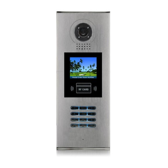
1.Parts and Functions Camera Lens Night View LED Adjustable Camera Speaker LCD Screen Connectiong Port RF CARD ID Card Window 3 2 1 Digital Keypad Microphone 128 mm With rainy cover 2. Terminal Descriptions SD Card Slot CN-LK T/R -T/R+ 3 2 1 RF CARD J/KMB... -
Page 3: Door Station Mounting
3.Door Station Mounting Camera angle Drill a hole and attach the The view for rainy Adjust the camera angle and attach the rainy cover to it cover after mounted metal to the panel and wire correctly. Attach screws to fix the Attach the unit to the rainy Attach the baffle to protect metal box... -
Page 4: Door Lock Connections
4. Door Lock Connections 1. Internal Power Supply Mode Use the power of the system to supply for the electronic lock, so that the lock can be connected to the door station directly, without an additional power supply for the electronic lock. Note that the door station can only output 12Vdc power, therefore the kind of lock is limited. -
Page 5: External Power Supply Mode
2. External Power Supply Mode When the electronic lock is over 12 Vdc, additional power supply for the lock is needed. • The power supply for the lock must be less than 48Vdc 1.5A. • The Jumper must be removed when using external power supply. The default setting is Power-to-Unlock type(Normally open mode), if use Power-off-to-Unlock type, change... -
Page 6: Door Station Configurations
5. Door Station Configurations 1. About room code(address): Room Code(also called room address) is a code assigned to each monitor, to identify different monitors; each monitor have a unique room code in one buidling.The room Code is stored in each Monitor’s inner EEPROM memory, and does not lose even the monitor is power off. 2. - Page 7 Table 1: Item Submenu 1. ID Code 2. Unlock Timing [05] 3. Unlock Output 4. Card Memory 5. Doorplate Mode 1. Installer Setup 6. Audio Options ... 7. Parameters ... 8. Installer Code ... 9. Default ... 1. Language 2. Tone Select [03] 3.
- Page 8 Basic Tools Detail: Table 2(Installer Setup): Factory Item Description If only one door station is installed in this building, set to 1; If multi door stations are installed, primary door station ID Code Single must be set to 1, and other slave door stations must be set from 2 to 4.
- Page 9 Table 2.1(Parameters): Factory Item Description Monitor Timing To show the monitor time,Range from 6s to 600s To show the surveillance time for each Door Station or Switch Timing CCTV camera.Range from 6s to 600s Wait Timing To show the calling wait time,Rang from 10s to 600s To show the limitation time of talking,Range from 10s Talk Timing to 600s...
- Page 10 Table 3(Setup): Factory Item Description To change language.the code format is 4 digits.Please refer Language to part 5,section 10(change door station language) for more detail informations. Select the chime of Door Station in calling wait state, 12 Tone Select chord tunes are available, key in 01 to 12 to select. Adjust the tone volume for dooor station in calling.Rang from Tone Volume 01~15...
- Page 11 Table 4(Card Memory): Factory Item Description Add Card ... To add the user card Delete By Card To delete card by user card Delete By M.code To delete card by room code Cards Information To show the informations about cards Format To format informations about cards 4.
-
Page 12: Change Ring Tone
1 . I D C o d e . [ 1 ] > > D e b u g S t a t e < < 2 . U n l o c k T i m i n g [ 0 5 ] 3 . - Page 13 7. Change Installer Code(administrator password): The Installer Code is the password to access the door station debug State. The default Installer Code is '66666666'. Note that if the Default Set have been activated, the Installer Code will be set to default value. 1 .
- Page 14 9. Change Unlcok Code: If door station runs as Debug State, you can press “1#” to activate Tools Menu, then select “2” to enter setup page,then select 4 item.If it runs as Normal State, follow these steps: 1 . L a n g u a g e [ 1 ] 2 .
- Page 15 1 . A d d C a r d . . . 1 . A d d C a r d . . . 1 . A d d C a r d . . . [ - - ] [ 0 1 ] [ 0 1 ] C a r d numbs : 1 5 9 7 7 1 3 1...
-
Page 16: Card Information
Card information: 4 . C a r d s I n f o r m a t i o n Enter Card Information page, and the screen will display the authorized User Cards count, and card read access Card Count: 1000 events count. - Page 17 1 . L a n g u a g e [ 1 ] 1 . L a n g u a g e 2 . To n e S e l e c t [ 0 3 ] 3 . To n e V o l u m e [ 0 3 ] Setup [ 8002 ] [ - - - - ]...
- Page 18 Check online monitors: > > D e b u g S t a t e < < 4 . O n l i n e M o n i t o r s 1 . I n s t a l l e r S e t u p 0 - # R e d i a l Tools...
-
Page 19: Specification
6. Specification ● Power supply: DC24V(Powered by DPA-D2A) ● Camera Lens: 1/4 ACS 4T image sensor with DSP processor ● Power consumption: Standby 3W;Working status 9W ● Screen: 3.5 inch TFT ● Resolution: 320(R, G, B)X240 pixels ● Video signal: CCIR/EIA Optional...