
Related Manuals for Lanner LEC-3034


Summary of Contents for Lanner LEC-3034
- Page 1 All manuals and user guides at all-guides.com LEC-3034_user manual Industrial Communication Platforms LEC-3034 User Manual Version: 1.1 Date of Release:2019-06-10...
- Page 2 - assumed to be qualified in the servicing of computer equipment, such as professional system integrators, or service personnel and technicians. The latest version of this document can be found on Lanner’s official website, available either through the product page or through the...
- Page 3 This document is copyrighted © 2019 by Lanner Electronics Inc. All rights are reserved. The original manufacturer reserves the right to make improvements to the products described in this manual at any time without notice.
- Page 4 7F, No.173, Sec.2, Datong Rd. Xizhi District, 层 New Taipei City 221, Taiwan T: +886-2-8692-6060 F: +886-2-8692-6101 T: +86 010-82795600 contact@lannerinc.com F: +86 010-62963250 service@ls-china.com.cn Taiwan Lanner Electronics Inc. 47790 Westinghouse Drive Fremont, CA 94539 T: +1-855-852-6637 F: +1-510-979-0689 T: +886-2-8692-6060 sales_us@lannerinc.com F: +886-2-8692-6101 contact@lannerinc.com Canada...
- Page 5 All manuals and user guides at all-guides.com LEC-3034_user manual This equipment has been tested and found to comply with the limits for a Class A digital device, pursuant to Part 15 of FCC Rules. These limits are designed to provide reasonable protection against harmful interference in a residential installation.
- Page 6 All manuals and user guides at all-guides.com Follow these guidelines to ensure general safety: Keep the chassis area clear and dust-free during and after installation. Do not wear loose clothing or jewelry that could get caught in the chassis. Fasten your tie or scarf and roll up your sleeves.
- Page 7 All manuals and user guides at all-guides.com LEC-3034_user manual an explosion. Leaving a battery in an extremely high temperature surrounding environment can result in an explosion or the leakage of flammable liquid or gas. A battery subjected to extremely low air pressure that may result in an explosion or the leakage of flammable liquid or gas.
- Page 8 The installation of this product must be performed by trained specialists; otherwise, a non-specialist might create the risk of the system’s falling to the ground or other damages. Lanner Electronics Inc. shall not be held liable for any losses resulting from insufficient strength for supporting the system or use of inappropriate installation components.
- Page 9 All manuals and user guides at all-guides.com LEC-3034_user manual Before turning on the device, ground the grounding cable of the equipment. Proper grounding (grounding) is very important to protect the equipment against the harmful effects of external noise and to reduce the risk of electrocution in the event of a lightning strike.
- Page 10 All manuals and user guides at all-guides.com This equipment must be grounded. The power cord for the product should be connected to a socket-outlet with earthing connection. Cet équipement doit être mis à la terre. La fiche d'alimentation doit être connectée à une prise de terre correctement câblée Suitable for installation in Information Technology Rooms in accordance with Article 645 of the National Electrical Code and NFPA 75.
- Page 11 All manuals and user guides at all-guides.com LEC-3034_user manual Key Features ..........................12 Package Content ......................... 12 Ordering Information ......................... 12 System Specifications ......................... 12 Physical Overview ........................14 Motherboard Information ......................20 Opening the Chassis ........................28 Installing the Key Components ....................29 Installing the SSD ........................
-
Page 12: Chapter 1: Product Overview
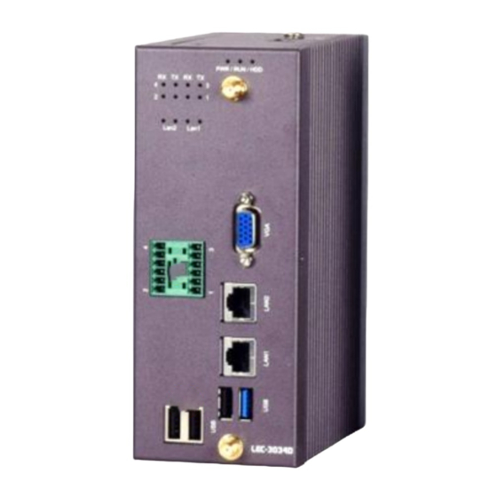
All manuals and user guides at all-guides.com Chapter 1: Product Overview Lanner LEC-3034 Series is a wireless rugged fanless edge gateway featuring dual-core Intel® Atom E3825 (codenamed BayTrail), optional 4G-LTE Mobile Connectivity, DDR3L SO-DIMM memory up to 8GB, 1 x SATA connector with 2.5”... - Page 13 All manuals and user guides at all-guides.com LEC-3034_user manual Intel® Atom™ Processor E3825 1.33 GHz CPU with Processor Options Heat-sink fanless thermal solution Frequency 1.33 GHz Processor System Core Number Chipset BIOS AMI SPI Flash BIOS Technology DDR3L 1067MHz Memory Max.
- Page 14 All manuals and user guides at all-guides.com Chapter 1: Product Overview...
- Page 15 All manuals and user guides at all-guides.com LEC-3034_user manual Description COM Transmission Indicator System Status Indicator LED Indicators Once powered, this system will then start running automatically with the PWR LED lit up. Wait for several minutes until System Status LED lights up to indicate that your system is up and running.
- Page 16 All manuals and user guides at all-guides.com Chapter 1: Product Overview...
- Page 17 All manuals and user guides at all-guides.com LEC-3034_user manual...
- Page 18 All manuals and user guides at all-guides.com Chapter 1: Product Overview...
- Page 19 All manuals and user guides at all-guides.com LEC-3034_user manual Description Reset Button Use a pin to reset the system DC Input For power supply Grounding Point For a proper cable to connect the ground...
- Page 20 All manuals and user guides at all-guides.com Chapter 1: Product Overview The motherboard layout shows the connectors and jumpers on the board. Refer to the following picture as a reference of the pin assignments and the internal connectors.
- Page 21 All manuals and user guides at all-guides.com LEC-3034_user manual The daughterboard carries SATA port and serial COM ports, the pin definition of which can be found in COM Port Pin-out.
- Page 22 All manuals and user guides at all-guides.com Chapter 1: Product Overview PWR1: Power Button Jumper Description Power ON/OFF system NC (Default) Normal CLR1: Clear CMOS Jumper Description Clear CMOS NC (Default) Normal J3 (Daughterboard):RS485 Switch Pin No. Description 1-2 (Default) RS485 Enable...
- Page 23 All manuals and user guides at all-guides.com LEC-3034_user manual SPIROM1: SPI ROM Connector (For RD debug) Description Description SPI_HOLD_N SPI_CS1_R_N SPI_CS0_R_N V_3P3_SPI_R SPI_MISO_R SPI_HD0_N SPI_CLK SPI_MOSI_R LPC1: LPC Connector (For RD debug) Description Description LPC_CLK_1 LPC_AD1 PLTRST_P80_N LPC_AD0 LPC_FRAME_N P3V3 LPC_AD3 LPC_AD2 J3 (Motherboard): Board to Board Connector 2x50P...
- Page 24 All manuals and user guides at all-guides.com Chapter 1: Product Overview Description Description Description Description LAN2_L1000_N_R COM4_RXD LAN2_ACTLED_N SW3_PCIE_TX_DN COM4_TXD SWLAN_PCIE_TX_DN LAN1_L100_N_R SW3_PCIE_TX_DP COM4_RTS# SWLAN_PCIE_TX_DP LAN1_L1000_N_R COM4_CTS# LAN1_ACTLED_N SW3_PCIE_RX_DN COM3_RXD SWLAN_PCIE_RX_DN LAN1_L100_N_R SW3_PCIE_RX_DP COM3_TXD SWLAN_PCIE_RX_DP SMB_SOC_CLK_3P3 COM3_RTS# SMB_SOC_DATA_3P3 CLK_SWCOM_PCIE_DN COM3_CTS# CLK_100M_PCIE2_DN COM5_DSR# CLK_SWCOM_PCIE_DP...
- Page 25 All manuals and user guides at all-guides.com LEC-3034_user manual Pin No. Description Pin No. Description P3V3SB_M2 P3V3SB_M2 PWROFF# USB_P0_DP USB_P0_DN UIM1_RST1 UIM1_CLK1 UIM1_DAT1 UIM1_PWR P3V3SB_M2 P3V3SB_M2 P3V3SB_M2...
- Page 26 All manuals and user guides at all-guides.com Chapter 1: Product Overview SIM1: Nano SIM Card Reader Description Description UIM_PWR UIM_RST# UIM_CLK UIM_DATA Please insert the SIM card into the socket as shown in the picture. Its golden contacts should face down. JUSB1: USB2.0 pin header Description Description...
- Page 27 All manuals and user guides at all-guides.com LEC-3034_user manual MPCIE1: MSATA Connector (Half Size) Pin No. Description Pin No. Description RSVD VCC3 RSVD RSVD RSVD RSVD RSVD RSVD RSVD RSVD RSVD RSVD RSVD Mechanical Key RSVD RSVD RSVD RSVD SATA RX+ VCC3 SATA RX- RSVD...
- Page 28 All manuals and user guides at all-guides.com Chapter 2: Hardware Installation To reduce the risk of personal injury, electric shock, or damage to the system, please remove all power connections to shut down the device completely. Also, please wear ESD protection gloves when conducting the steps in this chapter.
- Page 29 All manuals and user guides at all-guides.com LEC-3034_user manual In order to install the key components including M.2 card, mSATA card, the Nano SIM card and memory module, please remove (1) the heat sink that secures the daughter board, (2) the screws that secure the VGA connector on front panel and (3) the screws that secure the daughterboard on the standoffs.
- Page 30 All manuals and user guides at all-guides.com Chapter 2: Hardware Installation Install the key parts and make sure you replace the heatsink originally attached to the sockets mSATA Memory...
- Page 31 All manuals and user guides at all-guides.com LEC-3034_user manual 1. Remove the SSD bracket originally attached to the top cover and install the SSD onto it. Make sure you secure the disk onto the bracket with four disk screws. 2. Fix the bracket with SSD loaded onto the top cover, and connect the SATA cable and SATA power cable as shown in the picture.
-
Page 32: Chapter 3: Bios Setup
All manuals and user guides at all-guides.com Chapter 3: BIOS Setup To enter the BIOS setup utility, follow the steps below: 1. Boot up the system. 2. Pressing the <Tab> or <Del> key immediately allows you to enter the Setup utility, then you will be directed to the BIOS main screen. - Page 33 All manuals and user guides at all-guides.com LEC-3034_user manual Setup main page contains BIOS information and project version information. (The screenshots presented in this section are for reference only) Item Description BIOS Vendor: American Megatrends Core Version: AMI Kernel version, CRB code base, X64 Compliancy: UEFI version, PI version BIOS Information Project Version: BIOS release version...
- Page 34 All manuals and user guides at all-guides.com Chapter 3: BIOS Setup Select the Advanced menu item from the BIOS setup screen to enter the “Advanced” setup screen. Users can select any of the items in the left frame of the screen.
- Page 35 All manuals and user guides at all-guides.com LEC-3034_user manual This option allows you to configure parameters about Super IO Chip. Press <Enter> to access the submenu. Select the desired Serial Port Configuration item to enter sub setting screen.
-
Page 36: Serial Port 1 Configuration
All manuals and user guides at all-guides.com Chapter 3: BIOS Setup Serial port 1 Configuration Item Option Description Enabled Serial Port Enables or disables Serial Port 1. Disabled Device Settings IO=3F8h; IRQ = 4... - Page 37 All manuals and user guides at all-guides.com LEC-3034_user manual Item Description SYS1 Temp This value reports the CPU temperature. SYS2 Temp This value reports the System temperature. CPU VCORE This value reports the CPU VCORE. This value reports the 5V Input voltage. DCIN This value reports the DC Input voltage.
- Page 38 All manuals and user guides at all-guides.com Chapter 3: BIOS Setup Item Description Disabled On Board LAN LAN1 Select On Board LAN # boot Boot LAN2...
- Page 39 All manuals and user guides at all-guides.com LEC-3034_user manual Feature Options Description Select Com Mode as COM1 Mode RS-232/485/422 Disabled COM1 Termination COM RS-485/422 Receiver Termination Enabled Select Com Mode as COM2 Mode RS-232/485/422 Disabled COM2 Termination COM RS-485/422 Receiver Termination Enabled Select Com Mode as COM3 Mode...
- Page 40 All manuals and user guides at all-guides.com Chapter 3: BIOS Setup Disabled COM4 Termination COM RS-485/422 Receiver Termination Enabled Select Com Mode as COM5 Mode RS-232/485/422 Disabled COM5 Termination COM RS-485/422 Receiver Termination Enabled Select Com Mode as COM6 Mode RS-232/485/422 Disabled COM6 Termination...
- Page 41 All manuals and user guides at all-guides.com LEC-3034_user manual Item Description Limit CPUID Disabled Disable for Windows XP Maximum Enabled Disabled Execute Disable Bit Execute Disable Bit Enabled When enabled, a VMM can utilize the additional Intel Virtualization Disabled hardware capabilities provided by Vanderpool Technology Enabled Technology...
- Page 42 All manuals and user guides at all-guides.com Chapter 3: BIOS Setup Socket 0 CPU Information...
-
Page 43: Sata Mode
All manuals and user guides at all-guides.com LEC-3034_user manual Feature Options Description Disabled Serial-ATA (SATA) Enable/Disable Serial ATA Enabled Gen1 SATA Speed Support SATA Speed Support Gen1 or Gen2 Gen2 IDE Mode SATA MODE Select EDE/AHCI AHCI Mode Disabled Serial-ATA Port 0 Enable/Disable Serial ATA PORT 0 Enabled Disabled... - Page 44 All manuals and user guides at all-guides.com Chapter 3: BIOS Setup Feature Options Description Enables Legacy USB support. Enabled Auto option disables legacy support if no USB Legacy USB Support Disabled devices are connected; Auto Disabled option will keep USB devices available only for EFI applications.
- Page 45 All manuals and user guides at all-guides.com LEC-3034_user manual 10 sec 20 sec Maximum time the device will take before it properly reports itself to the Host Controller. Auto Device power-up delay Auto uses default value: for a Root port, it is 100 Manual ms, for a Hub port the delay is taken from Hub descriptor.
- Page 46 All manuals and user guides at all-guides.com Chapter 3: BIOS Setup Feature Options Description Enabled Enables TXE function. Disabled When user wants to update TXE to set this Enabled TXE HMRFPO item to enable, but this item only can Disabled active once.
- Page 47 All manuals and user guides at all-guides.com LEC-3034_user manual Select the Chipset menu item from the BIOS setup screen to enter the “Chipset” setup screen. Users can select any of the items in the left frame of the screen.
- Page 48 All manuals and user guides at all-guides.com Chapter 3: BIOS Setup Feature Options Description Dynamic 2 GB 2.25 GB Max TOLUD Maximum Value of TOLUD. 2.5 GB 2.75 GB 3 GB...
- Page 49 All manuals and user guides at all-guides.com LEC-3034_user manual...
- Page 50 All manuals and user guides at all-guides.com Chapter 3: BIOS Setup Feature Options Description Enabled Disabled XHCI Mode Mode of operation of xHCI controller. Auto Smart Auto...
- Page 51 All manuals and user guides at all-guides.com LEC-3034_user manual Select the Security menu item from the BIOS setup screen to enter the Security Setup screen. Users can select any of the items in the left frame of the screen. Feature Description If ONLY the Administrator's password is set, it only limits Administrator Password...
- Page 52 All manuals and user guides at all-guides.com Chapter 3: BIOS Setup Select the Boot menu item from the BIOS setup screen to enter the Boot Setup screen. Users can select any of the items in the left frame of the screen. Feature Options Description...
- Page 53 All manuals and user guides at all-guides.com LEC-3034_user manual Select the Save and Exit menu item from the BIOS setup screen to enter the Save and Exit Setup screen. Users can select any of the items in the left frame of the screen. Save Changes and Reset ■...
- Page 54 All manuals and user guides at all-guides.com Chapter 3: BIOS Setup ■ Restore Defaults Restore default values for all setup options. Select “Yes” to load Optimized defaults. Note The items listed under Boot Options will depend on the devices connected to this system.
- Page 55 All manuals and user guides at all-guides.com LEC-3034_user manual To install the Intel® LAN controller base driver for the Red Hat® and Linux operating system, please visit http://www.lannerinc.com/support/download-center/drivers, enter the product category and download the utility package of this system. For the latest driver update, please visit Intel®...
-
Page 56: Appendix B: Terms And Conditions
All manuals and user guides at all-guides.com Appendix B: Terms and Conditions 1. All products are under warranty against defects in materials and workmanship for one year from the date of purchase. 2. The buyer will bear the return freight charges for goods returned for repair within the warranty period; whereas the manufacturer will bear the after service freight charges for goods returned to the user. - Page 57 All manuals and user guides at all-guides.com LEC-3034_user manual When requesting RMA service, please fill out the following form. Without this form enclosed, your RMA cannot be processed.