Advertisement
Quick Links
Advertisement

Related Manuals for Lanner LEC-7233


Summary of Contents for Lanner LEC-7233
- Page 1 Industrial Communication Platforms LEC-7233 User Manual Version: 1.6 Date of Release:2021-09-02...
- Page 2 - assumed to be qualified in the servicing of computer equipment, such as professional system integrators, or service personnel and technicians. The latest version of this document can be found on Lanner’s official website, available either through the product page or through the...
- Page 3 This document is copyrighted © 2021 by Lanner Electronics Inc. All rights are reserved. The original manufacturer reserves the right to make improvements to the products described in this manual at any time without notice.
- Page 4 T: +86 010-82795600 大同路二段 173 號 7 樓 F: +86 010-62963250 T: +886-2-8692-6060 service@ls-china.com.cn F: +886-2-8692-6101 contact@lannerinc.com Lanner Electronics Inc. Lanner Electronics Canada Ltd. 47790 Westinghouse Drive 3160A Orlando Drive Fremont, CA 94539 Mississauga, ON T: +1-855-852-6637 L4V 1R5 Canada F: +1-510-979-0689 T: +1 877-813-2132 sales_us@lannerinc.com...
- Page 5 LEC-7233 User Manual Intel® and Intel® Atom are trademarks of Intel Corporation or its subsidiaries in the U.S. and/or other countries. Microsoft Windows and MS-DOS are registered trademarks of Microsoft Corp. All other product names or trademarks are properties of their respective owners.
- Page 6 Follow these guidelines to ensure general safety: Keep the chassis area clear and dust-free during and after installation. Do not wear loose clothing or jewelry that could get caught in the chassis. Fasten your tie or scarf and roll up your sleeves. Wear safety glasses if you are working under any conditions that might be hazardous to your eyes.
- Page 7 LEC-7233 User Manual Leaving a battery in an extremely high temperature surrounding environment can result in an explosion or the leakage of flammable liquid or gas. A battery subjected to extremely low air pressure that may result in an explosion or the leakage of flammable liquid or gas.
- Page 8 The installation of this product must be performed by trained specialists; otherwise, a non-specialist might create the risk of the system’s falling to the ground or other damages. Lanner Electronics Inc. shall not be held liable for any losses resulting from insufficient strength for supporting the system or use of inappropriate installation components.
- Page 9 LEC-7233 User Manual Before turning on the device, ground the grounding cable of the equipment. Proper grounding (grounding) is very important to protect the equipment against the harmful effects of external noise and to reduce the risk of electrocution in the event of a lightning strike. To uninstall the equipment, disconnect the ground wire after turning off the power.
- Page 10 Suitable for installation in Information Technology Rooms in accordance with Article 645 of the National Electrical Code and NFPA 75. Peut être installé dans des salles de matériel de traitement de l'information conformément à l'article 645 du National Electrical Code et à la NFPA 75. The machine can only be used in a restricted access location and has installation instructions by a skilled person (for Fan side).
- Page 11 LEC-7233 User Manual Key Features ..........................12 Ordering Information ......................... 12 System Specifications ......................... 13 Physical Overview ........................14 Opening the Chassis ........................24 Installing SO-DIMM Memory ...................... 25 Installing mSATA and Mini-PCIe Module ..................26 BIOS Setup ..........................27 Main Page ...........................
-
Page 12: Chapter 1: Product Overview
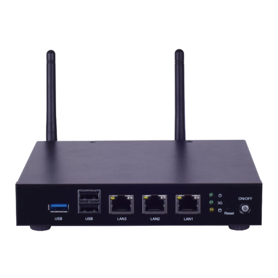
Chapter 1: Product Overview The LEC-7233, an industrial embedded system is empowered by Intel Baytrail CPU, with the option of Celeron N2807 or J1900. LEC-7233 provides the necessary performance with low power consumption, ideal as industrial embedded gateway. Regarding I/O features, LEC-7233 supports 3 x LAN ports, 2 x USB 2.0 ports, 1 x USB 3.0 port, 2 x COM ports and 1 x HDMI port. - Page 13 LEC-7233 User Manual Processor Options Intel® Bay Trail Celeron® N2807 Frequency 1.58GHz Processor System Core Number BIOS AMI SPI Flash BIOS Fanless Technology DDR3L 1333MHz Memory Max. Capacity 4 GB Socket 1x 204-pin SODIMM Controller Intel® i211 Ethernet Speed 10/100/1000Mbps...
- Page 14 Chapter 1: Product Overview Description USB 3.0 1 x USB3.0 Type-A port USB 2.0 2 x USB2.0 Type-A ports 3 x 10/100/1000 mbps RJ-45 LAN ports ⚫ Green: power-on/off status LEDs ⚫ Green: wireless network status Yellow: storage access Reset 1 x Reset button Power Switch 1 x power on/off switch...
- Page 15 LEC-7233 User Manual Description DC-IN 1 x DC input jack 5-pin terminal block supporting 4xDI and 4xDO 2 x D-sub COM ports with RS-232/485 signals HDMI 1 x HDMI port SMA Antenna 2 x SMA antenna holes (the antennas are NOT included by default) (optional) WARNING: Improper installation can cause injury or property damage.
- Page 16 Chapter 1: Product Overview The motherboard layout shows the connectors and jumpers on the board. Refer to the following picture as a reference of the pin assignments and the internal connectors. HDMI1 JSP1 DIO1 DC JACK1 COM1-2 SATAPWR1 SATA1 MPE3 MPE1 DIMM1 MSATA1...
- Page 17 LEC-7233 User Manual HDMI1: High-Definition Multimedia Interface connector Description Description DATA2+ DATA2- DATA1+ DATA1- DATA0+ DATA0- CLK+ CLK- DDC CLK DDC DAT HDMI_VCC...
- Page 18 Chapter 1: Product Overview JVGA1: 12-pin internal VGA pin header Description Description Description CRT_R CRT_G CRT_B HSYNC_1 VSYNC_1 D2DAT D2CLK LAN1/2/3: LAN Connector (RJ-45 connector with LED) Description TXD+ MD0+ TXD- MD0- RXD+ MD1+ MD2+ MD2- RXD- MD1- MD3+ MD3- 10-/100-/1000+ 10+/100+/1000- Active LED- (yellow)
- Page 19 LEC-7233 User Manual USB2/USB3: USB2.0 Type-A Connectors in double-stacked form Description USB_VCC1 -USB +USB USBB2/3 USB_VCC2 -USB +USB DIO: 2x5-pin Digital I/O terminal block with 4 x DI and 4 x DO Signal Signal DI_0 DO_0 DI_1 DO_1 DI_2 DO_2...
- Page 20 Chapter 1: Product Overview JTPM1: TPM module pin header for security and protection Signal Signal LPC_SERIRQ_H V3P3A LPC_AD0 V3P3A LPC_AD1 LPC_FRAM# PLTRST#_LS PLTRST# LPC_AD3 LPC_AD2 LPC1: LPC (low pin count) pin header for debug purpose Description Description LPC_CLK LAD1 PLTRST LAD0 LFRAME# 3.3V...
- Page 21 LEC-7233 User Manual +3.3V +3.3V LED_WLAN# +1.5V +3.3V MPCIE3: mini-PCIe Slot /w SIM (Half Size) Description Description +3.3V +1.5V PWR_UIM1 DAT_UIM1 CLK_UIM1 RST_UIM1 VPP_UIM1 PERST# +3.3V +1.5V SMB_CLK SMB_DAT USB_D- USB_D+ +3.3V +3.3V LED_WWAN# +1.5V +3.3V...
-
Page 22: Pin Description
Chapter 1: Product Overview MSATA1: mSATA slot for storage device (full-sized form) Description Description +3.3V SATA_RXp +3.3V MSATA1 SATA_RXn SATA_TXn SATA_TXp +3.3V +3.3V +3.3V DCIN1: DC Power Jack Description CMOS1 CMOS1 DC_IN (12V) DC_IN (-) Normal(Def) Clear CMOS... - Page 23 LEC-7233 User Manual CMOS1: Clear CMOS Short Pins Description Normal (Default) Clear CMOS J_RST1: 2-pin reset pin header Description Ground Reset SPI1: SPIROM pin header for debug purpose Description Description SPI_HOLD SPI_CS# SPI_VCC SPI1 SPI_MO SPI_CLK SPI_MI...
- Page 24 Also, please wear ESD protection gloves when conducting the steps in this chapter. To access some components and perform certain service procedures, you must perform the following procedures first. 1. Power off LEC-7233 and remove power cord. 2. Remove the screws from all sides and the rear, as circled in the image below.
- Page 25 LEC-7233 User Manual The system is designed with a SO-DIMM socket supporting up to 4GB DDR3L 1333MHz. Please follow the steps below for proper installations. 1. Locate the SO-DIMM socket on the motherboard. 2. Align the memory module’s key with the SO-DIMM socket’s key.
- Page 26 Chapter 2: Hardware Installation The system provides a mSATA and a mini-PCIe sockets for internal storage. Please follow the steps below for installations. 1. Locate the mSATA and the mini-PCIe socket, the system includes one mSATA (MSATA1), one half-sized mini-PCIe (MPE1) and one full-sized mini-PCIe (MPE3) sockets. The system will detect no mSATA or mini- PCIe card if put the wrong location.
- Page 27 LEC-7233 User Manual LEC-7233 has AMI BIOS built-in, with a Setup utility that allows users to configure required settings or to activate certain system features. Pressing the <Tab> or <Del> key immediately allows you to enter Setup utility. Control Keys...
-
Page 28: Chapter 3: Software Setup
Chapter 3: SOFTWARE SETUP Setup main page contains BIOS information and project version information. Feature Description BIOS Vendor: American Megatrends Core Version: AMI Kernel version BIOS Information Compliancy: UEFI version, PI version Project Version: BIOS release version System Date To set the Date, use <Tab> to switch between Date elements. System Time To set the Date, use <Tab>... - Page 29 LEC-7233 User Manual Select the Advanced menu item from the BIOS setup screen to enter the “Advanced” setup screen. Users can select any of the items in the left frame of the screen.
- Page 30 Chapter 3: SOFTWARE SETUP Feature Options Description Disable Enables or Disables BIOS support for security device. O.S. will not Security Device Enable show Security Device. TCG EFI protocol and INT1A interface will not Support be available. TPM 1.2 TPM 1.2 will restrict support to TPM 1.2 devices, TPM 2.0 restrict TPM 2.0 support to TPM 2.0 devices, Auto will support both with the default Device Select...
- Page 31 LEC-7233 User Manual...
- Page 32 Chapter 3: SOFTWARE SETUP Feature Options Description Disabled Serial Port Enable or Disable Serial Port (COM) Enabled Device Settings IO=3F8h; IRQ = 4; Loopback RS-232 COM1 MODE Select Com Mode as RS-232/RS485/RS422 RS-485 RS-422...
- Page 33 LEC-7233 User Manual Feature Options Description Disabled Serial Port Enable or Disable Serial Port (COM) Enabled Device Settings IO=3F8h; IRQ = 4; Loopback RS-232 COM2 MODE Select Com Mode as RS-232/RS485/RS422 RS-485 RS-422...
-
Page 34: Cpu Configuration
Chapter 3: SOFTWARE SETUP CPU Configuration Feature Options Description Limit CPUID Disabled for Windows XP Disabled Maximum Enabled Execute Disable Bit XD can prevent certain classes of malicious buffer overflow attacks Disabled when combined with a supporting OS (Windows Server 2003 SP1, Enabled Windows XP SP2, SuSE Linux 9.2, RedHat Enterprise 3 Update 3.) Intel Virtualization... - Page 35 LEC-7233 User Manual...
- Page 36 Chapter 3: SOFTWARE SETUP Feature Description CPU temperature This value reports the CPU temperature. System temperature This value reports the System temperature. VCORE This value reports the CPU VCORE. VGFX This value reports the VGFX. VCC5V This value reports the VCC5V Input voltage. VCC12V This value reports the VCC12V Input voltage.
- Page 37 LEC-7233 User Manual Feature Options Description Enabled Serial-ATA (SATA) Enable / Disable Serial ATA Disabled Gen1 SATA Speed Support SATA Speed Support Gen1 or Gen2 Gen2 IDE Mode SATA Mode Select IDE / AHCI AHCI Mode Enabled Serial-ATA Port 0...
- Page 38 Chapter 3: SOFTWARE SETUP Feature Options Description Disabled CSM Support Enable/Disable CSM Support. Enabled UPON REQUEST – GA20 can be disabled using BIOS Upon Request services. GateA20 Active Always ALWAYS – do not allow disabling GA20; this option is useful when any RT code is executed above 1MB. Force BIOS Option ROM Messages Set display mode for Option ROM...
- Page 39 LEC-7233 User Manual Feature Options Description Enables Legacy USB support. Enabled Auto option disables legacy support if no USB devices Legacy USB Support Disabled are connected. Disabled option will keep USB devices Auto available only for EFI applications. Enabled XCHI Legacy Support Enable/Disable XHCI Controller Legacy support.
- Page 40 Chapter 3: SOFTWARE SETUP Feature Options Description Disabled PXE Function LAN1 Select On Board LAN for enable PXE boot function. LAN2 LAN3...
- Page 41 LEC-7233 User Manual Select the Chipset menu item from the BIOS setup screen to enter the “Chipset” setup screen. Users can select any of the items in the left frame of the screen.
- Page 42 Chapter 3: SOFTWARE SETUP Feature Options Description 2 GB 2.25 GB Max TOLUD Maximum Value of TOLUD. 2.5 GB 2.75 GB 3 GB...
- Page 43 LEC-7233 User Manual Feature Options Description Enabled High Precision Enable or Disable the High Precision Event Timer. Disabled Power Off Select AC power state when power is re-applied after a Restore AC Power Loss Power On power failure. Last State...
- Page 44 Chapter 3: SOFTWARE SETUP Feature Options Description Enabled USB 2.0(EHCI) Control the USB EHCI (USB 2.0) functions. One EHCI Support controller must always be enabled Disabled Enabled USB Port 0 Enable / Disable USB Port 0 Disabled Enabled USB Port 1 Enable / Disable USB Port 1 Disabled Enabled...
- Page 45 LEC-7233 User Manual Select the Security menu item from the BIOS setup screen to enter the Security Setup screen. Users can select any of the items in the left frame of the screen. Feature Description Administrator If ONLY the Administrator's password is set, then this only limit Password access to Setup and is only asked for when entering Setup.
- Page 46 Chapter 3: SOFTWARE SETUP Select the Boot menu item from the BIOS setup screen to enter the Boot Setup screen. Users can select any of the items in the left frame of the screen. Feature Options Description Number of seconds to wait for setup activation key. Setup Prompt Timeout 65535(0xFFFF) means indefinite waiting.
- Page 47 LEC-7233 User Manual Select the Save and Exit menu item from the BIOS setup screen to enter the Save and Exit Setup screen. Users can select any of the items in the left frame of the screen. ■ Save Changes and Reset When Users have completed the system configuration changes, select this option to save the changes and reset from BIOS Setup in order for the new system configuration parameters to take effect.
- Page 48 Chapter 3: SOFTWARE SETUP ■ Discard Changes and Exit Select this option to quit Setup without saving any modifications to the system configuration. The following window will appear after the “Discard Changes and Exit” option is selected. Select “Yes” to Discard changes and Exit Setup.
- Page 49 LEC-7233 User Manual A watchdog timer is a piece of hardware that can be used to automatically detect system anomalies and reset the processor in case there are any problems. Generally speaking, a watchdog timer is based on a counter that counts down from an initial value to zero. The software selects the counter’s initial value and periodically restarts it.
-
Page 50: Appendix B: Terms And Conditions
Appendix B: Terms and Conditions 1. All products are under warranty against defects in materials and workmanship for one year from the date of purchase. 2. The buyer will bear the return freight charges for goods returned for repair within the warranty period; whereas the manufacturer will bear the after service freight charges for goods returned to the user. - Page 51 LEC-7233 User Manual When requesting RMA service, please fill out the following form. Without this form enclosed, your RMA cannot be processed.