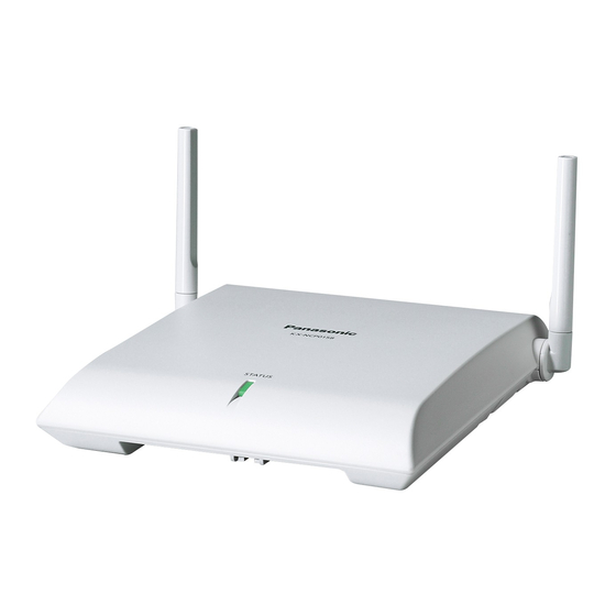
Panasonic KX-NCP0158 Quick Installation Manual
Dect 6.0 8-channel ip cell station unit
Hide thumbs
Also See for KX-NCP0158:
- Quick installation manual (88 pages) ,
- Quick installation manual (72 pages)
Table of Contents
Advertisement
Quick Links
Advertisement
Table of Contents

Related Manuals for Panasonic KX-NCP0158


Summary of Contents for Panasonic KX-NCP0158
- Page 1 DECT 6.0 8-Channel IP Cell Station Unit KX-NCP0158 Model No. Thank you for purchasing a Panasonic DECT 6.0 8-Channel IP Cell Station Unit. Please read this manual carefully before using this product and save this manual for future use. Document Version: 2009-06...
- Page 2 Important Information Important Information SAVE THESE INSTRUCTIONS Safety Notices Please observe the safety notices in this manual in order to avoid danger to users or other people, and prevent damage to property. The notices are classified as follows, according to the severity of injury or damage: WARNING This notice means that misuse could result in death or serious injury.
- Page 3 Important Information • When driving the screws into the wall, be careful to avoid touching any metal laths, wire laths or metal plates in the wall. • To prevent malfunction, deformity, overheating, rust, and discoloration, do not install or place equipment in the following types of locations: –...
- Page 4 Important Information Additional Information F.C.C. REQUIREMENTS AND RELEVANT INFORMATION CAUTION Any changes or modifications not expressly approved by the party responsible for compliance could void the user's authority to operate this device. Note This equipment has been tested and found to comply with the limits for a Class B digital device, pursuant to Part 15 of the FCC Rules.
-
Page 5: Table Of Contents
Table of Contents Table of Contents 1 Overview ....................6 2 Procedure Overview ................12 3 Site Planning ..................14 4 Before Site Survey .................25 5 Site Survey Using the KX-TD7685/KX-TD7695/KX-TD7696 ....30 6 After Site Survey ..................35 7 Connecting IP Cell Stations ..............37 8 Registering IP Cell Stations ..............42 9 Confirming the Status of Air Synchronization for IP Cell Stations ....................47... -
Page 6: Overview
1 Overview 1 Overview System Overview The IP Cell Station Unit (IP-CS) can be connected to a PBX via a LAN. The IP-CS supports existing DECT 6.0 Portable Stations (PSs) with the same features as using a traditional CS. The IP-CS allows for easy and cost-saving installation using an existing IP network infrastructure. - Page 7 1 Overview Air Synchronization It is necessary to establish synchronization for stable operation and handover between IP-CSs and other CSs. As a method of synchronization, air synchronization is used. Headquarters Headquarters Remote Office Remote Office IP-CS IP-CS Switching Hub Router Router Switching Hub IP-CS...
- Page 8 1 Overview System Connection Examples Connection Example Characteristics Using one IP-CS only • No need to conduct site planning and When installing only one IP-CS at a remote office. site survey for air synchronization. Switching Hub IP-CS Using multiple IP-CSs •...
- Page 9 1 Overview Names and Locations RJ45 Modular Antennas DC Jack CS ID Number (ID: xxxxxxxxxx) DIP Switch Unpacking Unpack the box and check the items below: Cell Station Wall Mounting Plate Screws Washers LED Indications Indication Color Description STATUS Green/Red/ CS status indication Amber •...
- Page 10 For more details about the Portable Station (PS), refer to the Operating Instructions of the PS. Maximum Number of CSs Supported by PBX Notice The CSs are for connection to specified Panasonic PBXs only. The following number of CSs can be supported by each PBX. Maximum Number...
- Page 11 1 Overview RF Specification Item Description Radio Access Method MultiCarrier TDMA-TDD Frequency Band 1920 MHz to 1930 MHz Number of Carriers Carrier Spacing 1728 kHz Bit Rate 1152 kbps Carrier Multiplex TDMA, 24 (Tx12, Rx12) slots per frame Frame Length 10 ms Modulation Scheme GFSK...
-
Page 12: Procedure Overview
2 Procedure Overview 2 Procedure Overview When connecting the wireless system, use extreme care in conducting the site survey. Site surveys can be conducted using the KX-TD7685/KX-TD7695/KX-TD7696 PS. An incorrectly performed site survey can result in poor service area, frequent noise, disconnection of calls, and synchronization failure for CSs. 1. - Page 13 2 Procedure Overview Turn off the PS. Stop supplying power, and return all DIP switches of each CS to the OFF position. 5. Connect the CS to the PBX Refer to "7 Connecting IP Cell Stations". Assign IP address information to the CS using the IP Terminal Maintenance Console. Connect the CS to the PBX over a LAN.
-
Page 14: Site Planning
3 Site Planning 3 Site Planning Choosing the best site for the CS requires careful planning and testing of essential areas. The best location may not always be convenient for installation. Read the following information before installing the unit. Understanding Radio Waves Characteristics of Radio Waves The transmission of radio waves and the CS coverage area depend on the structure and materials of the building. - Page 15 3 Site Planning Object Material Transmission Tendency Wall Concrete The thicker they are, the less radio waves penetrate them. Ferroconcrete Radio waves can penetrate them, but the more iron there is, the more radio waves are reflected. Window Glass Radio waves usually penetrate them. Glass with wire net Radio waves can penetrate them, but tend to be reflected.
- Page 16 3 Site Planning CS Coverage Area for Establishing Conversation Using PSs The example below shows the size of the area where one CS can cover PSs, if it is installed in an area with no obstacles. Note Radio signal strength levels are measured during the site survey (refer to "5 Site Survey Using the KX-TD7685/KX-TD7695/KX-TD7696").
- Page 17 3 Site Planning Implementing Air Synchronization CS Coverage Area for Air Synchronization between CSs The example below shows the size of the area where one CS can synchronize with other CSs, if it is installed in an area with no obstacles. Note Radio signal strength levels are measured during the site survey (refer to "5 Site Survey Using the KX-TD7685/KX-TD7695/KX-TD7696").
- Page 18 3 Site Planning CS Classifications CSs are assigned to any one of the following three classifications for implementing air synchronization: CS Class Description Master CS1 (synchronization Generates clock signal. source clock) Master CS2 (backup for Receives clock signal from Master CS1 (can also generate Master CS1) clock signal if Master CS1 malfunctions).
- Page 19 3 Site Planning • It is recommended that the number of levels in the synchronization hierarchy is minimized for stable air synchronization. The maximum number of levels is 4. Notice A repeater can only receive the clock signal from one source CS (Secondary CS cannot be set). Therefore, when you extend the coverage area using repeaters, minimize the number of IP-CSs that are synchronized with the repeater.
- Page 20 3 Site Planning Recommended Configuration IP-CS Traditional CS Primary CS Secondary CS [Configuration Example 1] Diagram Slave CS3 Slave CS1 Slave CS5 Master CS1 Master CS2 Slave CS4 Slave CS2 Slave CS6 Air Synchronization Tree : Hierarchy levels (e.g., Master CS2: 1st hierarchy level) Slave CS5 or or Slave CS3...
- Page 21 3 Site Planning [Configuration Example 2] Diagram Slave CS5 Slave CS1 Master CS1(B) Slave CS4 Slave CS8 Slave CS7 Slave CS3 Master CS1(A) Slave CS2 Slave CS6 Air Synchronization Tree : Hierarchy levels (e.g., Slave CS1: 1st hierarchy level) Slave CS7 or or or or Slave CS5...
- Page 22 3 Site Planning Site Survey Preparation Obtain a map and investigate the installation site. Check the obstacles (e.g., shelves, columns, and partitions). Check the materials of the structures (e.g., metal, concrete, and plywood). Check the layout and dimensions of the room, corridor, etc. Write down the above information on the map.
- Page 23 3 Site Planning CS installation plan: • The coverage area of each CS will not extend as far as when there are no obstacles, because the radio signals will be weakened by separating walls. Therefore, you will need 6 CSs to cover the entire room. 120 m (394 ft) 60 m (197 ft)
- Page 24 3 Site Planning Air Synchronization Tree Primary CS Secondary CS Hierarchy levels (e.g., Master CS2: 1st hierarchy level) Slave CS3 or or Slave CS1 Master CS1 Master CS2 Slave CS2 or or Slave CS4 Quick Installation Guide Document Version 2009-06...
-
Page 25: Before Site Survey
4 Before Site Survey 4 Before Site Survey Use the KX-TD7685/KX-TD7695/KX-TD7696 PS to conduct the site survey. Note Display prompts for the site survey are only available in English. Checking the CS ID Number Check the CS ID number label attached to the CS. If the CS ID number label is not attached to the CS, check the CS ID number using the Maintenance Console. - Page 26 4 Before Site Survey Setting and Installing the CS Temporarily for Site Survey Switch the Radio Signal Test switch from OFF to ON. Set the channel number switches as desired. DIP Switch Channel Number Switch Keep this switch at the default "OFF"...
- Page 27 4 Before Site Survey CAUTION The DC jack cover poses a choking hazard. Keep the DC jack cover out of reach of children. To AC Adaptor Cover KX-A421 (PSLP1662) [Connecting the Battery] WARNING • Make sure that you do not short the battery or cables. •...
- Page 28 4 Before Site Survey User-supplied Items Battery: VRLA (Valve Regulated Lead Acid) 12 V DC ´ 1 • • Battery cable: PSJS02P57 Cover Battery Cable PSJS02P57 Fuse Black Battery (12 V DC) Power Supply Duration Battery Conditions: 12 V DC, 2.5 Ah to 28 Ah Example Battery Capacity Power Supply Duration...
- Page 29 4 Before Site Survey [Connecting the PoE Hub or PoE Adaptor] To PoE Hub/PoE Adaptor Ethernet Straight Cable Install the CS temporarily for the site survey. Install the CS at least 2 m (6 ft 7 in) above the floor, and place the antennas so that they are pointing in directions that are 90 degrees apart (for antenna diversity), as follows: 45º...
-
Page 30: Site Survey Using The Kx-Td7685/Kx-Td7695/Kx-Td7696
5 Site Survey Using the KX-TD7685/KX-TD7695/KX-TD7696 5 Site Survey Using the KX-TD7685/ KX-TD7695/KX-TD7696 The PS has a Radio Signal Test mode that monitors the state of the radio link to the CS for site survey. In Radio Signal Test mode, the frame loss and signal strength of a synchronous slot, and the signal strength of the other slots can be measured when the PS is monitoring the CS. - Page 31 5 Site Survey Using the KX-TD7685/KX-TD7695/KX-TD7696 consistently 2% or more, there may be interference from external wireless equipment. In this case, the following may happen regardless of the radio signal strength level. Error Rate for Establishing Conversation Using PSs Error Rate Description Approx.
- Page 32 5 Site Survey Using the KX-TD7685/KX-TD7695/KX-TD7696 Move away from the CS and identify the CS coverage area within which the radio signal strength level is greater than "3". Draw the area on the map. L:12 L:05 L:03 Radio Signal Strength Levels For Establishing Conversation Using PSs Level: 11 to 12 Better...
- Page 33 5 Site Survey Using the KX-TD7685/KX-TD7695/KX-TD7696 • When planning the location of CS , make sure that CSs (clock signal sources) are within the area where the radio signal strength level of CS is "5". Make sure that the radio signal strength level is greater than "3" at any location in the service area required by the user.
- Page 34 5 Site Survey Using the KX-TD7685/KX-TD7695/KX-TD7696 • If multiple CSs cover the same area, the phone connection may become noisy or the number of possible simultaneous calls with PSs may decrease due to interference between the CSs. As a guideline, the maximum number of CSs in an area with a radio signal strength of "11" is 2. Referring to the Stored Scan Data Using the KX-TD7685/KX-TD7695/KX-TD7696 Log No.
-
Page 35: After Site Survey
6 After Site Survey 6 After Site Survey After obtaining the proper measurement results, exit Radio Signal Test mode by following the procedure below, before registering the CS to the PBX. Hold down the POWER button on the PS until the PS is off. Disconnect the CS from the AC adaptor, battery, PoE hub, or PoE adaptor to stop supplying electricity. - Page 36 6 After Site Survey Switch all DIP switches on the CS from ON to OFF. Quick Installation Guide Document Version 2009-06...
-
Page 37: Connecting Ip Cell Stations
7 Connecting IP Cell Stations 7 Connecting IP Cell Stations Assigning IP address Information When the IP-CS is connected to the LAN for the first time, you must assign IP addressing information to the IP-CS. The IP addressing information for the IP-CS can be assigned automatically through a DHCP server or entered manually using the IP Terminal Maintenance Console. - Page 38 7 Connecting IP Cell Stations Assign the IP addressing information automatically through a DHCP server or enter it manually. Note It is not necessary to configure the Primary PBX IP Address setting regardless of whether or not you are using a DHCP server, because it is detected automatically.
- Page 39 7 Connecting IP Cell Stations IP-CS is connected to must be set to "Trunk" port, to allow VLAN tagging. Consult your network administrator for details. • It is possible to connect the IP-CS to the LAN while registering the IP-CS to the PBX. For details, refer to "8 Registering IP Cell Stations".
- Page 40 7 Connecting IP Cell Stations WARNING When installing or testing a product with an external AC adaptor, the AC adaptor should be plugged into a wall outlet or floor-mounted AC outlet. Do not connect the AC adaptor to a ceiling-mounted AC outlet, as the weight of the adaptor may cause it to become disconnected.
- Page 41 7 Connecting IP Cell Stations Pass the cord through the groove of the IP-CS in one of the following three ways. To AC Adaptor KX-A421 (PSLP1662) To AC Adaptor KX-A421 (PSLP1662) To AC Adaptor KX-A421 (PSLP1662) Connect the AC cord to the AC adaptor, then connect the AC cord to an AC outlet. Document Version 2009-06 Quick Installation Guide...
-
Page 42: Registering Ip Cell Stations
8 Registering IP Cell Stations 8 Registering IP Cell Stations Registering the IP-CS Note When using a traditional CS in the same area, connect it to the PBX first, as Master CS1, and then register IP-CSs. Connect the PC to the PBX with an Ethernet straight cable or RS-232C cross cable. Click Connect from the program launcher. - Page 43 8 Registering IP Cell Stations Highlight IP-CSs and click the right arrow to select them for registration. Click Next. A screen will appear with information on the selected IP-CS for programming. Note • If the IP-CS has been connected to the LAN and power has been turned on, the IP address of the PBX will be assigned automatically.
- Page 44 8 Registering IP Cell Stations Select the desired classification for the CS in the CS Class column. Note For details about other parameters on this screen, refer to the PC Programming Manual for your PBX. Click Command to return the status of the port to "INS". Setting the Synchronizing CS Search Order (Primary/Secondary) The search order of each CS can be set by the following procedure: Under Maintenance, click Air Synchronization.
- Page 45 8 Registering IP Cell Stations Note When uninstalling IP-CSs that are supplying the clock signal, air synchronization is lost. If there is an IP-CS that is synchronized with the IP-CS that is being uninstalled, reconstruct the air synchronization tree beforehand so that the uninstalled IP-CS is not supplying the clock signal to any IP-CSs. Under Configuration, click Slot.
- Page 46 8 Registering IP Cell Stations Highlight IP-CSs and click the right arrow to select them for de-registration. Click Next. A dialog box will appear. Click OK. A dialog box will appear. Click Confirm. If the de-registration is successful, the dialog box will show "Forced de-registration succeed".
-
Page 47: Confirming The Status Of Air Synchronization For Ip Cell Stations
9 Confirming the Status of Air Synchronization for IP Cell Stations 9 Confirming the Status of Air Synchronization for IP Cell Stations After registering the IP-CS to the PBX, it is necessary to monitor the status of air synchronization for the IP-CS. If the monitoring results are not satisfactory, relocate the IP-CS or change the IP-CS that it is currently synchronized with to another CS using the Maintenance Console. - Page 48 9 Confirming the Status of Air Synchronization for IP Cell Stations Note For details about the procedure for changing the synchronizing CS, refer to "Assigning the Synchronizing CSs". If you want to collect the monitored data, click Capture. A dialog box will be displayed. Navigate to the folder in which you want to save the file.
-
Page 49: Registering Portable Stations
10 Registering Portable Stations 10 Registering Portable Stations Registering the PS The PS must be registered to the PBX before it can be used. Programming of both the PS and PBX is required. A Proprietary Telephone (PT) with multiline display (e.g., KX-T7636 6-line display) is required to perform the PBX system programming. - Page 50 10 Registering Portable Stations Changing the Display Language of the PS Using the KX-TD7685/KX-TD7695/KX-TD7696 Note The illustrations shown in the procedure are based on the KX-TD7696 throughout this section. Press POWER Select Select for 2 seconds. "Setting Handset". "Display Option". Select Select the desired "Select Language".
- Page 51 10 Registering Portable Stations If "Rejected" or "Time out" is displayed The registration information is still stored in the PS. You need to delete the registration information from the Using the KX-TD7685/KX-TD7695/KX-TD7696 Press POWER Select Select Select for 2 seconds. "Setting Handset".
-
Page 52: Wall Mounting
11 Wall Mounting 11 Wall Mounting Mounting WARNING • Make sure that the wall that the unit will be attached to is strong enough to support the unit (approx. 440 g [16 oz]). If not, it is necessary for the wall to be reinforced. •... - Page 53 11 Wall Mounting Hook the CS on the screw heads. Washer Drive the screw to this point. Place the antennas so that they are pointing in directions that are 90 degrees apart (for antenna diversity), as follows: 45º 90º 45º Document Version 2009-06 Quick Installation Guide...
- Page 54 11 Wall Mounting Reference for Wall Mounting Please copy this page and use as a reference for wall mounting. Install a screw here. 83 mm (3-1/4 in) 100 mm (3-15/16 in) Install a screw here. Note Make sure to set the print size to correspond with the size of this page. If the dimension of the paper output still deviates slightly from the measurement indicated here, use the measurement indicated here.
-
Page 55: Troubleshooting
12 Troubleshooting 12 Troubleshooting PROBLEM PROBABLE CAUSE SOLUTION • • • The LED of the CS does not CS is not connected Make sure that the cable is connected change to Green ON. properly. properly with correct pin assignments. Also, make sure that the cable does not make short circuits. - Page 56 12 Troubleshooting PROBLEM PROBABLE CAUSE SOLUTION • • • The CS is not busy (i.e., the CSs are located too close Reduce the number of CSs in the area, status of the LED is not together in the same area. or increase the distance between CSs Moderate Green Flashing), (refer to "5 Site Survey Using the...
-
Page 57: Restarting The Ip Cell Station
13 Restarting the IP Cell Station 13 Restarting the IP Cell Station If the IP-CS does not operate properly, restart the IP-CS. Before restarting the IP-CS, try the system feature again to confirm whether there definitely is a problem or not. The IP-CS settings are changed back to their factory default by restarting the IP-CS. -
Page 58: A Network Management
A Network Management A Network Management DHCP (Dynamic Host Configuration Protocol) Server To establish communication over a VoIP network, IP addresses must be assigned to IP-CSs and the PBX to identify their locations on the network. While these addresses can be assigned manually, it is also possible to use a DHCP server to automatically assign IP address information. -
Page 59: B Packet Control Features
B Packet Control Features B Packet Control Features Jitter Buffer When voice signals are packetized and transmitted, individual packets can take different paths through the network and arrive at the destination at varied timings. This is referred to as "jitter", and it can cause degradation in speech quality. -
Page 60: C Guidance For Voip Installation
C Guidance for VoIP Installation C Guidance for VoIP Installation C.1 VoIP Requirements Bandwidth Assessment When using IP-CSs, you must ensure that the IP network in use has enough bandwidth to support VoIP communications. If the amount of bandwidth required for VoIP communications is more than the network can accommodate, speech quality will be compromised. - Page 61 C Guidance for VoIP Installation Note When a DHCP server (which automates IP addressing of devices on the network) is not used, static IP addressing must also be enabled for all IP-CSs. Does only a single router provide access to the IP network? In a dual network, 2 routers provide access to the IP network as shown in the diagram below.
- Page 62 TCP/UDP Default Port No. RTP (IP-CS) Real-time Transport Protocol. 12000 to 12255 Used for voice data transmission. Maintenance (IPCMPR) Panasonic proprietary protocol. 39300 Used for communication parameter Maintenance (IP-CS) 9301 negotiation with the PBX, download of country/area data, confirmation of...
- Page 63 C Guidance for VoIP Installation Are layer 2 or higher switches used? Use of repeater hubs can increase the network load, and therefore may result in degradation in speech quality. To ensure high speech quality, use only layer 2 or higher switches. Use of layer 2 or higher switches is also strongly recommended for connecting IP-CSs.
-
Page 64: Voip Requirements Checklist
C Guidance for VoIP Installation C.2 VoIP Requirements Checklist Use the following checklists to see if you can implement a VoIP network. The answers identified in underlined bold-face letters are the required answers for the corresponding questions. Bandwidth Assessment Question Answer Memo Ref. - Page 65 C Guidance for VoIP Installation Question Answer Memo Ref. Are layer 2 or higher switches used? Model of switch: Do not use repeater hubs as they can increase the network load. p. 63 Also note that the port of the switching hub that connects to the IPCMPR card should be set to operate under "Auto Negotiation"...
-
Page 66: D Information About Ip Terminal Maintenance Console
D Information about IP Terminal Maintenance Console D Information about IP Terminal Maintenance Console Parameters Network Settings Parameter Value Range DHCP Client Disable, Enable IP Address 1-223.0-255.0-255.0-255 Subnet Mask 0-255.0-255.0-255.0-255 (except 0.0.0.0 and 255.255.255.255) Default Gateway 0-223.0-255.0-255.0-255 PBX IP Address 0-223.0-255.0-255.0-255 Port Settings Parameter... - Page 67 D Information about IP Terminal Maintenance Console Parameter Value Range DSP Version Version number Document Version 2009-06 Quick Installation Guide...
- Page 68 Copyright: This material is copyrighted by Panasonic Communications Co., Ltd., and may be reproduced for internal use only. All other reproduction, in whole or in part, is prohibited without the written consent of Panasonic Communications Co., Ltd. Panasonic Communications Co., Ltd. 2009 PSQX5024ZA KK1009HS0 (v0.004)