
Related Manuals for Panasonic FP7 CPU Unit


Summary of Contents for Panasonic FP7 CPU Unit
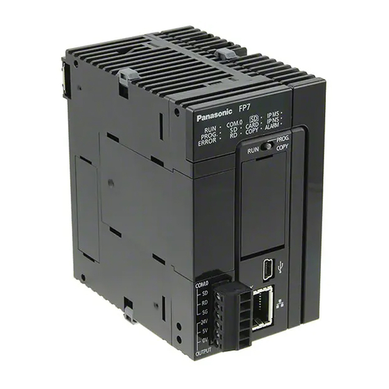
- Page 1 PROGRAMMABLE CONTROLLER FP7 CPU Unit User's Manual LAN port communication WUME-FP7LAN-01 2013.3 panasonic.net/id/pidsx/global...
-
Page 2: Safety Precautions
-This manual and its contents are copyrighted. -You may not copy this manual, in whole or part, without written consent of Panasonic Industrial Devices SUNX Co., Ltd. -Windows is a registered trademark of Microsoft Corporation in the United States and other countries. - Page 3 Introduction Thank you for buying a Panasonic product. Before you use the product, please carefully read the installation instructions and the users manual, and understand their contents in detail to use the product properly. Types of Manual • There are different types of users manual for the FP7 series, as listed below. Please refer to a relevant manual for the unit and purpose of your use.
-
Page 4: Table Of Contents
Types and Purposes of Communication Ports ........1-2 1.1.2 LAN Port Specifications ................1-3 Functions of LAN Port ................1-4 1.2.1 Communication Functions of FP7 CPU Unit ........... 1-4 1.2.2 System Connection ................. 1-4 1.2.3 User Connection ..................1-5 Overview of Communication Functions ..........1-6 1.3.1... - Page 5 Specifying Port Number ................ 3-12 4. Setting and Operation of User Connection ....... 4-1 Configuration Concerning Open Process ..........4-2 4.1.1 Connection of the FP7 CPU Unit ............4-2 4.1.2 Specifying Use of Connection ..............4-2 4.1.3 Open Method (Server/Client) ..............4-2 4.1.4...
- Page 6 Table of Contents 5. MEWTOCOL Master/Slave Communication ...... 5-1 Types of MEWTOCOL Communication ..........5-2 5.1.1 MEWTOCOL-DAT (Binary Communication) ........... 5-2 5.1.2 MEWTOCOL-COM (ASCII Communication) ........... 5-2 List of MEWTOCOL Supporting Commands .......... 5-3 5.2.1 MEWTOCOL-DAT ................... 5-3 5.2.2 MEWTOCOL-COM .................. 5-3 5.2.3 MEWTOCOL7-COM ................
-
Page 7: Specifications
Table of Contents 7. General-Purpose Communication ........7-1 Operation of General-Purpose Communication ........7-2 7.1.1 Read Data from an External Device ............7-2 7.1.2 Write Data into an External Device ............7-2 7.1.3 Sending Format in General-Purpose Communication ......7-3 Sending Operation .................. - Page 8 Table of Contents...
-
Page 9: Communication Functions Of Cpu Unit
Communication Functions of CPU Unit... -
Page 10: Communication Ports Of Cpu Unit
Communication Functions of CPU Unit 1.1 Communication Ports of CPU Unit 1.1.1 Types and Purposes of Communication Ports Communication ports of CPU unit Functions of Ports (1) COM1 and COM2 Ports Attach a separately sold communication cassette to use these ports. You can select from five types of communication cassettes. -
Page 11: Lan Port Specifications
Not used Functions of LED lamps (1) LINK Turns on when connection is established between the FP7 CPU unit and a device on Ethernet. (2) ACK Flashes when some communication is in progress with a connected device (e.g. sending/receiving a command or response). -
Page 12: Functions Of Lan Port
Configuration chart Communication functions of FP7 CPU Unit • The FP7 CPU Unit can open a virtual communication line with an Ethernet-supporting device connected to LAN, and send/receive data. • IP address of the FP7 CPU unit, protocol (TCP/UDP), connection method with devices, port numbers, etc. -
Page 13: User Connection
• The FP7 CPU Unit can open virtual communication lines for up to 16 connections with Ethernet-supporting devices connected to LAN, and send/receive data. • It can open multiple connections between the FP7 CPU unit and multiple nodes or a single node, and execute communication. -
Page 14: Overview Of Communication Functions
Communication Functions of CPU Unit 1.3 Overview of Communication Functions 1.3.1 MEWTOCOL-DAT Master/Slave Communication (Binary Communication) Overview of function • Execute communication using MEWTOCOL-DAT, a communication protocol usd by our PLC. • One of the PLC has the sending right, and executes communication by sending commands to PLCs that support MEWTOCOL-DAT, and receiving responses. -
Page 15: Mewtocol-Com Master/Slave Communication (Ascii Communication)
1.3 Overview of Communication Functions 1.3.2 MEWTOCOL-COM Master/Slave Communication (ASCII Communication) Overview of function • Execute communication using MEWTOCOL-COM, a communication protocol used by our PLC. • One of the device has the sending right, and executes communication by sending commands to devices that support MEWTOCOL-COM, and receiving responses. -
Page 16: Modbus Tcp Master/Slave Communication
Communication Functions of CPU Unit 1.3.3 MODBUS TCP Master/Slave Communication Overview of function • This is used for communicating with other devices that support the MODBUS TCP protocol. • In master communication, communication is performed when the master unit sends instructions (command messages) to slave units and the slave unit returns responses (response messages) according to the instructions. -
Page 17: General-Purpose Communication
1.3 Overview of Communication Functions 1.3.4 General-Purpose Communication Overview of function • General-purpose communication is used when PLC executes communication in accordance with the command specifications of the partner device. • Formulation and sending of command messages to the partner device, and reception processing of responses from the partner device, are performed by the user program. -
Page 18: Terms
Communication Functions of CPU Unit 1.4 Terms The following terms are used for settings on the software for connecting the FP7 CPU unit to Ethernet LAN, and in the Users Manuals. Server connection and client connection • These indicate methods for connecting a virtual communication line between FP7 and an external device. -
Page 19: Installation And Wiring
Installation and Wiring... -
Page 20: Installation Environment And Wiring For Lan Ports
Installation and Wiring 2.1 Installation Environment and Wiring for LAN Ports 2.1.1 Before Installation and Wiring Noise resistance of Ethernet The Ethernet is a network used in offices and buildings, where there is comparatively little noise. It does not have a higher resistance to noise than ordinary FA application networks. Caution is required when installing the hub, and when laying cables. -
Page 21: Wiring The Lan Port
2.2 Wiring the LAN Port 2.2 Wiring the LAN Port Selection of UTP cables • Use Category 5 UTP cable. • It is recommended to use a UTP cable of 10 m or shorter, taking account of noise resistance. •... -
Page 22: Noise Control Measures
Installation and Wiring 2.3 Noise Control Measures 2.3.1 Guidelines to Noise Generation • If any of the following are occurring, there is a danger that external noise is affecting the communication circuit. Appropriate measures should be taken. • Check to see if a communication error is occurring, in synchronization with the operation of the device. -
Page 23: Configuration
Configuration... -
Page 24: Procedure For Setting Communication Conditions
Configuration 3.1 Procedure for Setting Communication Conditions 3.1.1 Setup Procedure • To use communication functions based on the LAN port, communication conditions must be set. • Settings should be performed by the programming tool FPWIN GR7. PROCEDURE 1. From the menu bar, select "Option" > "FP7 Configuration". 2. -
Page 25: Setting Basic Communication Information
3.2 Setting Basic Communication Information 3.2 Setting Basic Communication Information 3.2.1 List of Setting Items List of setting items (basic communication information) Setting item Default Remark Automatic getting of IPv4 address Own IP address (IPv4) 192.168.1.5 Subnet mask (IPv4) 255.255.255.0 This is valid as long as the network (subnetwork) mask field is anything other than 0. -
Page 26: Setting Each Timer Value And Timeout Value
Configuration 3.2.2 Setting Each Timer Value And Timeout Value For setting each timer value and timeout value, please refer to the description below. Timer setting conditions in FPWIN GR7 Timer setting conditions in FPWIN GR7 are as follows. • TCP closed timer value ≥ TCP ULP timeout value ≥ TCP re-transmission timer value •... -
Page 27: Settings For Sntp Server
3.3 Settings for SNTP server 3.3 Settings for SNTP server These settings are required when the time is synchronized by SNTP while the calendar timer function is being used. List of setting items (SNTP server) Setting item Default Setting method Specification SNTP server address - Select the setting for SNTP server... -
Page 28: Settings For Ftp Server
Configuration 3.4 Settings for FTP server Select this to use the FTP server function. List of setting items (FTP server) Setting item Default Setting method Specifying use of FTP Select whether you will use the FTP server function. server Permission of anonymous If authentication by user account and password is not required, user... -
Page 29: Setting Of System Connection
3.5 Setting of System Connection 3.5 Setting of System Connection 3.5.1 List of Setting Items System connection is used when using a programming tool via LAN port. List of setting items Setting item Default System Connection - Setting method Operation Mode Setting MEWTOCOL-COM Select the operation mode MEWTOCOL-COM. - Page 30 Configuration Setting screen for system connection KEY POINTS • System connection is aimed at connecting a programming tool. Use this in default settings (MEWTOCOL-COM, server connection (unspecified partner), Auto OPEN, TCP/IP).
-
Page 31: Setting On The Programming Tool Side
3.5 Setting of System Connection 3.5.2 Setting on the Programming Tool Side • Settings should be performed on the programming tool FPWIN GR7 side. PROCEDURE 1. From the menu bar, select "Online" > "Communication Settings". The "Communication Settings" dialog box is displayed. 2. -
Page 32: Setting Of User Connection
Configuration 3.6 Setting of User Connection 3.6.1 List of Setting Items List of setting items Setting item Default Setting method Select an operating mode (MEWTOCOL-COM / MEWTOCOL-COM7 / MODBUS-TCP / Operation Mode Setting MEWTOCOL-COM MEWTOCOL-DAT / general-purpose communication). Specifying use of Not use Specify whether each connection is to be used. - Page 33 3.6 Setting of User Connection The MEWTOCOL communication type is a function to maintain compatibility • with the existing models of FP2 ET-LAN unit. For connection between FP7 units, default values should be used. For the open method, select "Open automatically". For server connection / •...
-
Page 34: Specifying Port Number
Configuration 3.6.2 Specifying Port Number Port number settings • Port numbers are allocated in order for the various communication processes provided by the TCP/IP or UDP/IP to be differentiated by the programmable controller or the computer. • The restrictions that apply to available port numbers are different for TCP/IP and UDP/IP, as indicated in the table below. -
Page 35: Setting And Operation Of User Connection
Setting and Operation of User Connection... -
Page 36: Configuration Concerning Open Process
4.1.1 Connection of the FP7 CPU Unit Operation of the FP7 CPU unit • The FP7 CPU unit opens a virtual communication line with devices in accordance with user connection information (open method, communication method, port number, partner unit IP address) in the configuration menu. -
Page 37: Instructions For Specifying Connection Conditions
4.1 Configuration Concerning Open Process 4.1.5 Instructions for Specifying Connection Conditions • In Ethernet communication using the FP7 unit, different operation modes, open method, and communication methods can be specified for each connection. • Specify the same conditions for operation mode (MEWTOCOL-DAT, MEWTOCOL-COM, MODBUS-TCP, general-purpose communication) and communication methods (TCP/IP, UDP/IP) for devices to be connected in each connection. -
Page 38: Communication Processing
• By default, the FP7 CPU unit is set to enable slave communication. • When master communication is to be performed from the FP7 CPU unit to devices, use the dedicated commands SEND/RECV. When general-purpose communication is to be performed, use GPSEND/GPRECV commands. -
Page 39: Input/Output Signals Used For Communication
4.3 Input/Output Signals Used for Communication 4.3 Input/Output Signals Used for Communication 4.3.1 I/O Allocation Input signal Input Response Effective Name Description signal connection Operation mode Connection 1 • When connection is ON in the general-purpose communication Connection 2 mode, the flag turns ON once data are received. - Page 40 Setting and Operation of User Connection Output signal Output Response Effective Name Description signal connection Operation mode Connection 1 • This reports the result when Connection 2 the execution of the general- purpose communication General-purpose sending command (GPSEND), communication Connection 10 or the master communication MEWTOCOL-COM...
-
Page 41: Mewtocol Master/Slave Communication
MEWTOCOL Master/Slave Communication... -
Page 42: Types Of Mewtocol Communication
MEWTOCOL Master/Slave Communication 5.1 Types of MEWTOCOL Communication 5.1.1 MEWTOCOL-DAT (Binary Communication) Instructions In master communication, PLC has the sending right, and executes communication by sending commands to devices that support MEWTOCOL-DAT, and receiving responses. Messages in accordance with the protocol are automatically generated by PLC. In the user program, reading and writing can be done simply by specifying the station no. -
Page 43: List Of Mewtocol Supporting Commands
5.2 List of MEWTOCOL Supporting Commands 5.2 List of MEWTOCOL Supporting Commands 5.2.1 MEWTOCOL-DAT Type of instruction Code Description Write data area Writes data to a data area. Read data area Reads the contents of a data area. Write contact information Turn ON or OFF contact in the specified area. -
Page 44: Mewtocol Master Communication (Recv)
MEWTOCOL Master/Slave Communication 5.3 MEWTOCOL Master Communication (RECV) 5.3.1 Read Data From an External Device Instructions In master communication, PLC has the sending right, and executes communication by sending commands to devices that support MEWTOCOL, and receiving responses. Messages in accordance with the protocol are automatically generated by PLC. In the user program, reading can be done simply by specifying the station no. - Page 45 5.3 MEWTOCOL Master Communication (RECV) Timing chart Conditions to enable execution of RECV Clear to send master command communication flag Clear to send flag (X90 - X9F): ON (X90 - X9F) Confirm ON Sending flag (Y90 - Y9F): OFF Confirm OFF Sending master Sending flag (Y90 - Y9F):...
-
Page 46: Recv Command (When Mewtocol Is Used)
MEWTOCOL Master/Slave Communication 5.3.2 RECV Command (When MEWTOCOL is Used) Command format Setting range Items Settings MEWTOCOL-DAT MEWTOCOL-COM Specify the operation unit. US / SS 1 - 64 (Note 1) Specify the partner station no. Specify the device initial address of the source 0 - 65535 0 - 99999 node data area in the partner node. -
Page 47: Mewtocol Master Communication (Send)
5.4 MEWTOCOL Master Communication (SEND) 5.4 MEWTOCOL Master Communication (SEND) 5.4.1 Write Data into an External Device Instructions In master communication, PLC has the sending right, and executes communication by sending commands to devices that support MEWTOCOL, and receiving responses. Messages in accordance with the protocol are automatically generated by PLC. - Page 48 MEWTOCOL Master/Slave Communication Timing chart Conditions to enable execution of SEND Clear to send master command communication flag Clear to send flag (X90 - X9F): ON (X90 - X9F) Confirm ON Sending flag (Y90 - Y9F): OFF Confirm OFF Sending master communication flag Sending flag (Y90 - Y9F):...
-
Page 49: Send Command (When Mewtocol Is Used)
5.4 MEWTOCOL Master Communication (SEND) 5.4.2 SEND Command (When MEWTOCOL is Used) Command format Setting range Setting Settings item MEWTOCOL-DAT MEWTOCOL-COM Specify the operation unit. US / SS Specify the header of the source node data (Note 1) area. 1 - 2038 words 1 - 507 words Specify the No. - Page 50 MEWTOCOL Master/Slave Communication 5-10...
- Page 51 MODBUS TCP Master/Slave Communication...
-
Page 52: Modbus Tcp Master/Slave Communication
MODBUS TCP Master/Slave Communication 6.1 MODBUS TCP Format 6.1.1 MODBUS TCP Data structure for the MODBUS TCP format • In MODBUS TCP, an MBAP header is attached to the function codes and data used in MODBUS-RTU. Function MBAP Header Data MODBUS TCP format Code... -
Page 53: List Of Modbus Tcp Supported Commands
6.2 List of MODBUS TCP Supported Commands 6.2 List of MODBUS TCP Supported Commands 6.2.1 List of MODBUS Function Codes Table of supported commands Remarks FP7 supported Code Name (MODBUS) Name (Reference no.) functions Read Coil Status Read Y and R Coils ●... -
Page 54: Modbus Tcp Master Communication (Recv)
MODBUS TCP Master/Slave Communication 6.3 MODBUS TCP Master Communication (RECV) 6.3.1 Read Data from an External Device Instructions In master communication, PLC has the sending right, and executes communication by sending commands to devices that support MODBUS, and receiving responses. Messages in accordance with the protocol are automatically generated by PLC. - Page 55 6.3 MODBUS TCP Master Communication (RECV) Starting conditions for RECV R100 execution ( ) Clear to send flag: ON Clear to send Sending master Execute Sending flag: OFF master communication flag RECV communication flag R100 Settings for communication port S1: CPU LAN port (U100) UNITSEL U100 S1: Connection 1 (U1)
- Page 56 MODBUS TCP Master/Slave Communication KEY POINTS Specify the connection No. targeted for communication, using UNITSEL • command immediately before SEND/RECV command. • Master communication is only valid when MEWTOCOL or MODBUS is selected. Confirm that the "clear to send master communication flag" (X90 - X9F) for the targeted connection is ON, and execute SEND/RECV command.
-
Page 57: Recv Command (Modbus Function Code Specified Type)
6.3 MODBUS TCP Master Communication (RECV) 6.3.2 RECV Command (MODBUS Function Code Specified Type) Command format Operand Items Settings Setting range Specify the operation unit. US / SS Specify the MODBUS function codes and partner station no. to be used. (Note 1) (Note 2) Higher Two hexadecimal digits that indicate the MODBUS H1 - H4 (1 - 4) -
Page 58: Recv Command (Modbus Function Code Unspecified Type)
MODBUS TCP Master/Slave Communication 6.3.3 RECV Command (MODBUS Function Code Unspecified Type) Command format Operand Items Settings Setting range Specify the operation unit. US / SS Specify the partner station no. H1 - HF7 (1 - 247) Specify the device initial address of the source node data area in the partner node. -
Page 59: Modbus Tcp Master Communication (Send)
6.4 MODBUS TCP Master Communication (SEND) 6.4 MODBUS TCP Master Communication (SEND) 6.4.1 Write Data into an External Device Instructions In master communication, PLC has the sending right, and executes communication by sending commands to devices that support MODBUS, and receiving responses. Messages in accordance with the protocol are automatically generated by PLC. - Page 60 MODBUS TCP Master/Slave Communication Timing chart Conditions to enable execution of SEND Clear to send master command communication flag Clear to send flag (X90 - X9F): ON (X90 - X9F) Confirm ON Sending flag (Y90 - Y9F): OFF Confirm OFF Sending master communication flag Sending flag (Y90 - Y9F):...
-
Page 61: Send Command (Modbus Function Code Specified Type)
6.4 MODBUS TCP Master Communication (SEND) 6.4.2 SEND Command (MODBUS Function Code Specified Type) Command format Operand Items Settings Setting range Specify the operation unit. US / SS Specify the header of the source node data area. (Note 1) 1 - 127 words Specify the No. -
Page 62: Send Command (Modbus Function Code Unspecified Type)
MODBUS TCP Master/Slave Communication 6.4.3 SEND Command (MODBUS Function Code Unspecified Type) Command format Operand Items Settings Setting range Specify the operation unit. US / SS Specify the header of the source node data area. (Note 1) 1 - 127 words Specify the No. -
Page 63: General-Purpose Communication
General-Purpose Communication... -
Page 64: Operation Of General-Purpose Communication
General-Purpose Communication 7.1 Operation of General-Purpose Communication 7.1.1 Read Data from an External Device Read data from a partner device In general-purpose communication, communication is executed by sending commands that suit the partner device, and receiving responses. Command messages are sent by formulating a data table for message in accordance with the protocol, on the given data register, and subsequently executing GPSEND command. -
Page 65: Sending Format In General-Purpose Communication
7.1 Operation of General-Purpose Communication 7.1.3 Sending Format in General-Purpose Communication Difference in operation based on selection of communication types • Data to be sent/received in LAN communication vary based on settings for user connection information: communication type. Communication Maximum no. -
Page 66: Sending Operation
General-Purpose Communication 7.2 Sending Operation 7.2.1 Overview of Sending Operation Sending in the general-purpose communication is performed by formulating a data table for sending on the given operation memory, and subsequently executing GPSEND command. External device Send message/data ABCDE DT100 00001 ・・・・・・・・... - Page 67 7.2 Sending Operation Timing chart • Data in the table specified by GPSEND command are sent, in ascending order from lower bytes. • While data are being sent, the sending general-purpose communication flag for the relevant connection (Y80 - Y8F) turns ON. The flag is turned OFF when sending is completed. •...
-
Page 68: Contents Of Sent Data
• The data size that can be sent in a single transmission based on GPSEND command from the LAN port of the FP7 CPU unit is up to 16,384 bytes. -
Page 69: Gpsend (General-Purpose Communication Sending Command)
7.2 Sending Operation 7.2.3 GPSEND (General-Purpose Communication Sending Command) Command format Setting Settings Setting range item Specify the operation unit. US / SS (Note 1) Specify the header of the source node data area. (Note 2) 1 - 16384 Specify the No. -
Page 70: Receiving Operation
General-Purpose Communication 7.3 Receiving Operation 7.3.1 Overview of Receiving Operation Procedures In the general-purpose communication mode, data received from the partner device are saved in the same reception buffer for each connection. When the GPRECV command is executed in a user program, data in the reception buffer can be copied into a given operation memory. External device Reception buffer (one for each connection) Receive message/data... - Page 71 Specify the connection targeted for communication, using UNITSEL command immediately before GPSEND command. • The data size that can be received in a single transmission based on GPRECV command from the LAN port of the FP7 CPU unit is up to 16,384 bytes.
-
Page 72: Contents Of Received Data
General-Purpose Communication 7.3.2 Contents of Received Data When data are copied into a given data register , based on GPRECV command, the data are saved in the following manner. Saving method for received data When data are saved in a given data register from the reception buffer, based on GPRECV command, the data are saved in the following manner. -
Page 73: Gprecv (General-Purpose Communication Receiving Command)
7.3 Receiving Operation 7.3.3 GPRECV (General-Purpose Communication Receiving Command) Command format Setting Settings Setting range item Specify the operation unit. US / SS Specify the initial address of the data area to save the received data. (Note 1) Specify the final address of the data area to save the received data. (Note 2) (Note 1): Devices that can be specified for D1 are: WX, WY, WR, WL, DT, LD. - Page 74 General-Purpose Communication 7-12...
-
Page 75: Specifications
Specifications... -
Page 76: Specifications Of Cpu Unit Lan Port Communication Function
Specifications 8.1 Specifications of CPU Unit LAN Port Communication Function LAN port Items Description Interface 100BASE-TX / 10BASE-T Baud rate 100 Mbps, 10 Mbps auto-negotiation (Note 1) Transmission system Baseband Max. segment length 100 m (Note 2) Communication cable UTP (Category 5) 100BASE-TX: 2 segments Max. -
Page 77: Mewtocol-Dat Format
8.2 MEWTOCOL-DAT Format 8.2 MEWTOCOL-DAT Format 8.2.1 MEWTOCOL-DAT Command Format in LAN Command Format • In data sent/received in LAN communication, a header is attached to the MEWTOCOL-DAT command data part, or the MEWTOCOL-DAT response data part, as indicated in the data structure below. -
Page 78: Mewtocol-Dat Command/Response Format
Specifications 8.2.2 MEWTOCOL-DAT Command/Response Format Format of command/response message Dedicated protocol by binary code in a dialog format Data contents (1) Header Make sure to indicate "80H" in the beginning of the message. (2) Command code and Response code Make sure to indicate "80H"... - Page 79 8.2 MEWTOCOL-DAT Format Example of command/response message Below is shown an example of "Read data area" (command code 51H).
-
Page 80: Mewtocol-Com Format
Specifications 8.3 MEWTOCOL-COM Format 8.3.1 MEWTOCOL-COM Command Format in LAN Communication Format of command/response message • Data to be sent/received in LAN communication vary based on settings for user connection information: MEWTOCOL communication type. Configuration MEWTOCOL Format of command and response communication type setting Only send the MEWTOCOL-COM command data part, or the MEWTOCOL- Do not connect with FP2-ET-LAN... -
Page 81: Mewtocol-Com Command Format
• The station no. of the PLC to which you want to send the command must be specified. The station no. of the PLC is specified by the system register. In the case of the FP7 CPU unit, the station no. is specified in the FPWIN GR7 configuration menu. - Page 82 Specifications The method for writing text segments in the message varies depending on • the type of command. • When the message to be sent contains a large number of characters, send the command divided in several times. • When the message contains a large number of characters, the response is sent divided in several times.
-
Page 83: Mewtocol-Com Response Format
8.3 MEWTOCOL-COM Format 8.3.3 MEWTOCOL-COM Response Format Response message After PLC receives a command, it returns the processing result. (1) Header (start code) • A “%” (ASCII code: H25) or “<” (ASCII code: H3C) must be at the beginning of a message. •... - Page 84 Specifications If no response is returned, the communication format may not be correct, or • the command may not have arrived at the PLC, or the PLC may not be functioning. Check if the specified connection is ON, or if the connection information setting is correct.
-
Page 85: Mewtocol7-Com Format
• The station no. of the receiving PLC to which you want to send the command must be specified with "@ and three digits". The station no. of the PLC is specified by the system register. In the case of the FP7 CPU unit, the station no. is specified in the FPWIN GR7 configuration menu. - Page 86 Specifications (5) Check code • This is a CRC (Cyclic Redundancy Check) to detect errors using a generating polynomial of hamming codes. • The CRC should be created so that it targets all of the text data from the header to the last text character.
-
Page 87: Mewtocol7 Response Format
8.4 MEWTOCOL7-COM Format 8.4.2 MEWTOCOL7 Response Format Response message (1) Header (start code) (2) Station no. of the receiver (3) Frame No. (4) Text (to be specified in accordance with the type of command) > Command name (data area read) Command code value Response code (normal status: $, abnormal status: !) Data (normal status: read data, abnormal... - Page 88 Specifications (5) Check code • This is a CRC (Cyclic Redundancy Check) to detect errors using a generating polynomial of hamming codes. • The CRC should be created so that it targets all of the text data from the header to the last text character.
- Page 89 Record of changes Manual No. Date Record of Changes WUME-FP7LAN-01 Mar.2013 First Edition...
- Page 92 ■ Overseas Sales Division (Head Office): 2431-1 Ushiyama-cho, Kasugai-shi, Aichi, 486-0901, Japan ■ Telephone: +81-568-33-7861 ■ Facsimile: +81-568-33-8591 panasonic.net/id/pidsx/global About our sale network, please visit our website. © Panasonic Industrial Devices SUNX Co., Ltd. 2013 March, 2013 PRINTED IN JAPAN WUME-FP7LAN-01...