HIKVISION 24 Series User Manual
Hide thumbs
Also See for 24 Series:
- Quick start manual (39 pages) ,
- User manual (26 pages) ,
- User manual (25 pages)
Table of Contents
Advertisement
Advertisement
Table of Contents

Related Manuals for HIKVISION 24 Series


Summary of Contents for HIKVISION 24 Series
- Page 1 24 Series Ethernet Switch User Manual UD03706B - I -...
- Page 2 Any and all information, including, among others, wordings, pictures, graphs are the properties of Hangzhou Hikvision Digital Technology Co., Ltd. or its subsidiaries (hereinafter referred to be “Hikvision”). This user manual (hereinafter referred to be “the Manual”) cannot be reproduced, changed, translated, or distributed, partially or wholly, by any means, without the prior written permission of Hikvision.
- Page 3 Regulatory Information FCC Information Please take attention that changes or modification not expressly approved by the party responsible for compliance could void the user’s authority to operate the equipment. FCC compliance: This equipment has been tested and found to comply with the limits for a Class A digital device, pursuant to part 15 of the FCC Rules.
- Page 4 Industry Canada ICES-003 Compliance This device meets the CAN ICES-3 (A)/NMB-3(A) standards requirements. Preparing for installation The HIKVISION 24 Series Ethernet Switch includes the following models: Model Name Ethernet Switch Symbol Conventions The symbols that may be found in this document are defined as follows.
-
Page 5: Table Of Contents
Table of Contents Chapter 1 24 SWITCH Introduction ..........................1 1.1 Appearance Description for Standard Configuration ..................... 1 1.2 24 SWITCH Systematic Characteristic Parameters ....................2 Chapter 2 Installation Preparation ..........................4 2.1 Caution of Usage ..............................4 2.2 Safety Advice ................................. 4 2.2.1 Safety Principles .............................. -
Page 6: Chapter 1 24 Switch Introduction
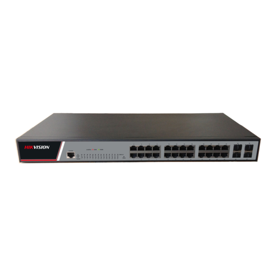
Chapter 1 24 SWITCH Introduction The section describes the characteristics and parameters of 24 SWITCH and gives an overview of 24 SWITCH. 1.1 Appearance Description for Standard Configuration The built-in ports of 24 SWITCH are: 24 gigabit Ethernet Base-T ports, 4 gigabit Ethernet SFP ports and 1 Console port. -
Page 7: Switch Systematic Characteristic Parameters
Forwards the 10/100M/1000M Ethernet 24 gigabit RJ45 ports electric signals Forwards 1000M Ethernet optical 4 SFP ports signals. Table 1-2 Parts at the front template of the 24 SWITCH Besides, 24 SWITCH has a grounding column and a power socket at its back. Figure 1-1 Back template of the 24 SWITCH Abbrev. - Page 8 Dimensions 440×230×45 (W×D×H) Operating temperature/ 0℃~45℃; 5%~95% non-condensing humidity Storage temperature/ -20℃~70℃; 5%~95% non-condensing humidity Input voltage: AC100~240V; Power characteristics Input frequency: 47~63Hz; - 3 -...
-
Page 9: Chapter 2 Installation Preparation
Chapter 2 Installation Preparation 2.1 Caution of Usage Similar to other electronic products, the semiconductor chip easily gets damaged if you power on or off abruptly and frequently. To restart up the switch of 24 SWITCH, you have to open the power on-off after the power is cut down for three to five seconds. -
Page 10: Safety Principles For Live Working
Read the installation guide carefully before you operate the system. Only professionals are allowed to install or replace the switch. Pull out the AC power socket and close the direct-current power before operating on the machine box or working beside the power source. ... -
Page 11: Electrostatic Discharge Damage Prevention
2.2.4 Electrostatic Discharge Damage Prevention Electrostatic discharge may damage devices and circuits. Improper treatment may cause the switch to malfunction completely or discontinuously. Move or locate the devices according to the measures of electrostatic discharge prevention, ensuring the machine box connects the ground. Another measure is to wear the static-proof hand ring. -
Page 12: Power Requirements
When you install the machine box at the open cabinet, prevent the frame of the cabinet from blocking the airway of the machine box. Ensure that nice ventilation is provided for the devices installed at the bottom of the cabinet. ... -
Page 13: Chapter 3 Installing The 24 Switch
Chapter 3 Installing the 24 SWITCH Caution: Only professionals are allowed to install or replace the devices. 3.1 Installation Flow of 24 SWITCH 3.2 Installing the Machine Box of the Switch The installation of the machine box has two modes: ... -
Page 14: Installing The Machine Box On The Cabinet
3.2.2 Installing the Machine Box on the Cabinet The machine box of the switch is fixed on the cabinet through the brackets. When you fix the brackets, the front template of the switch faces forward. The detailed operations are shown in Figure 3-1. Figure 3-1 Fixing the machine box of the switch After the brackets are installed, install the switch on the cabinet. - Page 15 Figure 3-3 RJ-45 connector of the console port Figure 3-4: Connecting the console port of 24 SWITCH with the computer Name Remarks No connect Input No connect Output No connect No connect No connect Table 3-1 Definition of the pins of the Console port Note: The console port of the 24 SWITCH does not support traffic control.
-
Page 16: Connecting Gigabit Ethernet Sfp Ports
Figure 3-5 Cable connection at the console port 3.3.2 Connecting Gigabit Ethernet SFP Ports The 24 SWITCH has 4 gigabit SFP ports. Each port has a corresponding indicator for showing their LINK/ACT state. If the indicator is always on, the port is normally linked;... -
Page 17: Checking After Installation
Because 24 10/100/1000Base-T ports of 24 SWITCH support the MDI/MDIX self-identification of the cable, 24 SWITCH can adopt five types of direct-through/cross network cables when it connects other Ethernet terminals. Figure 3-8 Connecting the 1000M Base-T port and other Ethernet terminals Pin name Abbr. - Page 18 If the switch is installed on the cabinet, check whether the installation point between the cabinet and the switch is strong. If the switch is installed on the desk, check whether there is enough space for the switch to discharge its heat and whether the desk is stable.
-
Page 19: Chapter 4 Maintaining Switch
Chapter 4 Maintaining Switch Caution: Before opening the machine box, make sure that you have released the static you carried and then turn off the power on-off of the switch. Before operating any step in Appendix B, read the section “Safety Advice”. Before performing operations beside the power source or on the machine box, turn off the power on-off and plug out the power cable. -
Page 20: Closing The Machine Box
Figure 4-1 Opening the chassis of 24 SWITCH When the cover is opened, put it aside. The mainboard of the system appears. Note: After taking off the cover, put it horizontally and avoid it to be crushed or collided. Otherwise, the machine box is hard to install. 4.2 Closing the Machine Box The section mainly describes how to put the cover and close the machine box. - Page 21 When the cover and the bottom are closely tied, let the cover slide the slot of the front template at the bottom. Nail the bolt and screw it tightly with the screwdriver. Reinstall the switch on the cabinet or the desk. Reconnect all cables of the switch.
-
Page 22: Chapter 5 Hardware Fault Analysis
Chapter 5 Hardware Fault Analysis The part describes how to remove the fault from the switch. 5.1 Fault Separation The key for resolving the systematic faults is to separate the fault from the system. You can compare what the system is doing with what the system should do to detect the fault. - Page 23 Abbrev. Name Description When the switch is powered on, the Power indicator indicator is on. When the indicator is always on, the system is being started up. System indicator When the indicator flickers, the system works well. If the indicator is on in orange: 10/100Mbps, LINK/ACT Port indicator...
-
Page 24: Chapter 6 Specifications
Chapter 6 Specifications Item 24 SWITCH Backplane 56Gbps Forwarding rate 42Mpps 1000Base-X 24 10/100/1000M Base-T ports+4 ports Ports Dimensions(W×D×H)(mm) 440*230*45 Consumption <15W AC : 100V-240V , 50Hz± 10% Power supply Operating temperature/humidity: 0 ℃ -45 ℃, 5%-95% non-condensing Environment Storage temperature/humidity: -20 ℃ -70 ℃; 5%-95% non-condensing Static configuration and dynamic MAC learning;... - Page 25 Flow monitoring and flow shaping Security L2/L3/L4 ACL flow identification and filtration DDoS attack prevention, TCP’s SYN Flood attack prevention, UDP Flood attack prevention, etc Broadcast/multicast/unknown unicast storm-control Port isolation Port security, and “IP+MAC+port” binding Static/LACP link aggregation Reliability EAPS and ERPS Console, Telnet, SSH2.0, Web SNMP v1/v2/v3 Management...
- Page 26 - 21 -...