
Related Manuals for Draytek VigorSwitch G2080


Summary of Contents for Draytek VigorSwitch G2080
- Page 1 VigorSwitch G2080 User’s Guide Version: 1.0 Date: 2008/03/06 Copyright 2008 All rights reserved.
-
Page 2: Copyright Information
Web registration is preferred. You can register your Vigor device via Owner http://www.draytek.com. Firmware & Tools Due to the continuous evolution of DrayTek technology, all devices will be regularly Updates upgraded. Please consult the DrayTek web site for more information on newest firmware, tools and documents. -
Page 3: Regulatory Information
This device complies with Part 15 of the FCC Rules. Operation is subject to the following two conditions: (1) This device may not cause harmful interference, and (2) This device may accept any interference received, including interference that may cause undesired operation. VigorSwitch G2080 User’s Guide... -
Page 4: Table Of Contents
1.5 Hardware Installation ... 6 1.5.1 Connecting the SFP Module to the Chassis... 6 1.5.2 Installing Optional SFP Fiber Transceivers to the switch ... 7 1.5.3 Installing Chassis to a 19-Inch Wiring Closet Rail ... 7 1.5.4 Cabling Requirements ... 7 1.5.5 Configuring the Management Agent of Switch ... - Page 5 2.18.2 Config File... 104 2.19 Diagnostics... 105 2.19.1 Diagnostics ... 105 2.19.2 Loopback Test ... 106 2.19.3 Ping Test... 106 2.20 TFTP Server... 107 2.21 Log ... 108 2.22 Firmware Upgrade ... 109 2.23 Reboot...110 2.24 Logout ...110 VigorSwitch G2080 User’s Guide...
- Page 6 Trouble Shooting ... 113 5.1 Resolving No Link Condition...113 5.2 Q & A ...113 VigorSwitch G2080 User’s Guide...
-
Page 7: Preface
IGMP Snooping capability via the intelligent software. It is suitable for both metro-LAN and office application. In this switch, Port 7 and Port 8 include two types of media --- TP and SFP Fiber (LC, BiDi LC…); this port supports 10/100/1000Mbps TP or 1000Mbps SFP Fiber with auto-detected function. -
Page 8: Features
IP multicast packets are running over the network. The VigorSwitch G2080, a standalone off-the-shelf switch, provides the comprehensive features listed below for users to perform system network administration and efficiently and securely serve your network. - Page 9 The trap event and alarm message can be transferred via e-mail and mobile phone short message Supports diagnostics to let administrator knowing the hardware status Supports external loopback test to check if the link is ok TFTP for firmware upgrade, system log upload and config file import/export VigorSwitch G2080 User’s Guide...
-
Page 10: Packing List
Please notify your sales representative immediately if any of the aforementioned items is missing or damaged. In the switch, Port 7~8 includes two types of media --- TP and SFP Fiber (LC, BiDi LC…); this port supports 10/100/1000Mbps TP or 1000Mbps SFP Fiber with auto-detected function. - Page 11 1 to 8 (Ethernet TP Port) Interface LAN P1 – P8 Reset One RS-232 DB-9 interface is offered for configuration or management. VigorSwitch G2080 User’s Guide Color Green Blinks when CPU is activity Lit when connection with the remote device is good.
-
Page 12: Hardware Installation
RJ-45 jack 1, 2, 3, 6 to 3, 6, 1, 2) can be used. It means you do not have to tell from them, just plug it. 1. Use Cat. 5 grade RJ-45 TP cable to connect to a TP port of the switch and the other end is connected to a network-aware device such as a workstation or a server. -
Page 13: Installing Optional Sfp Fiber Transceivers To The Switch
1. Wear a grounding device for electrostatic discharge. 2. Screw the mounting accessory to the front side of the switch (See Fig. 2-2). 3. Place the Chassis into the 19-inch wiring closet rail and locate it at the proper position. - Page 14 (BIDI LC) Takes the Delay Time into Account Theoretically, the switch partitions the collision domain for each port in switch cascading that you may up-link the switches unlimitedly. In practice, the network extension (cascading levels & overall diameter) must follow the constraint of the IEEE 802.3/802.3u/802.3z and other 802.1 series protocol specifications, in which the limitations...
- Page 15 If more than two switches are connected in the same network, select one switch as Level 1 switch and connect all other switches to it at Level 2. Server/Host is recommended to connect to the Level 1 switch. This is general if no VLAN or other special requirements are applied.
- Page 16 The same VLAN members could not be in different switches. Every VLAN members could not access VLAN members each other. The switch manager has to assign different names for each VLAN groups at one switch. Case 3: Port-based VLAN - 2 VLAN1 members could not access VLAN2, VLAN3 and VLAN4 members.
-
Page 17: Configuring The Management Agent Of Switch
We offer you three ways to startup the switch management function. They are RS-232 console, CLI, and Web. Users can use any one of them to monitor and configure the switch. You can touch them through the following procedures. Section 2-1-4-1: Configuring the Management Agent of VigorSwitch G2080 through the... - Page 18 VigorSwitch. Set IP Address, Subnet Mask and Default Gateway IP Address You can first either configure your PC IP address or change IP address of the switch, next to change the IP address of default gateway and subnet mask.
- Page 19 IP address or to know the IP address of the switch. Then, follow the procedures listed below. 1. Set up a physical path between the configured the switch and a PC by a qualified UTP Cat. 5 cable with RJ-45 connector.
- Page 20 Please refer to Fig. 2-9 about the switch’s default IP address information. 2. Run web browser and follow the menu. Please refer to Chapter 2 VigorSwitch G2080 User’s Guide...
-
Page 21: Ip Address Assignment
IP address range between 192.0.0.0 and 223.255.255.255. Each class C network has a 24-bit network prefix followed 8-bit host address. There are 2,097,152 (2^21)/24 networks able to be defined with a maximum of 254 (2^8 –2) hosts per network. VigorSwitch G2080 User’s Guide... - Page 22 They are the addresses with all zero’s and all one’s host number. For example, an IP address 128.1.2.128, what IP address reserved will be looked like? All 0s mean the network itself, and all 1s mean IP broadcast. 10.0.0.0 --- 10.255.255.255 172.16.0.0 --- 172.31.255.255 192.168.0.0 --- 192.168.255.255 VigorSwitch G2080 User’s Guide...
- Page 23 The gateway setting is used for Trap Events Host only in the switch. For assigning an IP address to the switch, you just have to check what the IP address of the network will be connected with the switch. Use the same network address and append your host address to it.
-
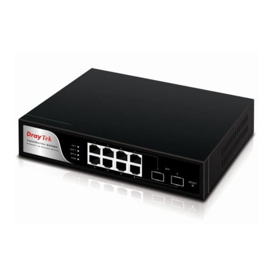
Page 24: Typical Applications
(such as a browser) will ask the DNS to resolve the IP address of the named server. The VigorSwitch G2080 implements 8 Gigabit Ethernet TP ports with auto MDIX and two slots for the removable module supporting comprehensive fiber types of connection including LC and BiDi-LC SFP modules. - Page 25 It is a system wide basic reference connection diagram. This diagram demonstrates how the switch connects with other network devices and hosts. Peer-to-peer application is used in two remote offices VigorSwitch G2080 User’s Guide...
- Page 26 Office network VigorSwitch G2080 User’s Guide...
-
Page 27: Operation Of Web-Based Management
Gigabit TP/SFP Fiber management Ethernet switch. With this facility, you can easily access and monitor through any one port of the switch all the status of the switch, including MIBs status, each port activity, Spanning tree status, port aggregation status, multicast traffic, VLAN and priority status, even illegal access record and so on. -
Page 28: Web Management Home Overview
This is helpful while malfunctioning. On the top side, it shows the front panel of the switch. In the front panel, the linked ports will display green; as to the ports, which are link off, they will be dark. For the optional modules, the slot will show only a cover plate if no module exists and will show a module if a module is present. - Page 29 Open the function folder, a sub-menu will be shown. The functions of each folder are described in its corresponded section respectively. When clicking it, the function is performed. The following list is the full function tree for web user interface. VigorSwitch G2080 User’s Guide...
-
Page 30: System Information
The model name of this device. As it is, this tells what this device is. Here, it is “L2 Managed Switch”. Basically, it is the location where this switch is put. User-defined. For easily managing and maintaining device, you may write down the contact person and phone here for getting help soon. -
Page 31: Ip Configuration
IP configuration is one of the most important configurations in the switch. Without the proper setting, network manager will not be able to manage or view the device. The switch supports both manual IP address setting and automatic IP address setting via DHCP server. - Page 32 Function name: IP Configuration Function description: Set IP address, subnet mask, default gateway and DNS for the switch. Parameter description: DHCP Setting: IP address: DHCP is the abbreviation of Dynamic Host Configuration Protocol. Here DHCP means a switch to turn ON or OFF the function.
- Page 33 Subnet mask: Default gateway: DNS Server VigorSwitch G2080 User’s Guide Subnet mask is made for the purpose to get more network address because any IP device in a network must own its IP address, composed of Network address and Host address, otherwise can’t communicate with other devices each other.
-
Page 34: Time Configuration
“Second” within the valid value range indicated in each item. If you input an invalid value, for example, 61 in minute, the switch will clamp the figure to 59. NTP is a well-known protocol used to synchronize the clock of the switch system time over a network. NTP, an internet draft standard formalized in system is version 3 protocol. - Page 35 VigorSwitch G2080 User’s Guide over the starting time, the system time will be increased one hour after one minute at the time since it passed over. And when the time passes over the ending time, the system time will be decreased one hour after one minute at the time since it passed over.
-
Page 36: Account Configuration
Through the management security configuration, the manager can do the strict setup to control the switch and limit the user to access this switch. The following rules are offered for the manager to manage the switch: Rule 1) : When no lists exists, then it will accept all connections. - Page 37 VLAN VID is able to be accepted or denied by the switch, the IP range of the user could be accepted or denied by the switch, the port that the user is allowed or not allowed to connect with the switch, or the way of controlling and connecting to the switch via Http, Telnet or SNMP.
- Page 38 A name is composed of any letter (A-Z, a-z) and digit (0-9) with maximal 8 characters. The switch supports two kinds of options for managed valid VLAN VID, including “Any” and “Custom”. Default is “Any”. When you choose “Custom”, you can fill in VID number.
-
Page 39: Virtual Stack
Virtual Stack Management (VSM) is the group management function. Through the proper configuration of this function, switches in the same LAN will be grouped automatically. And among these switch, one switch will be a master machine, and the others in this group will become the slave devices. -
Page 40: Port Configuration
It is used for the activation or de-activation of VSM. Default is Disable. The role that the switch would like to play in virtual stack. Two types of roles, including master and slave are offered for option. Default is Master. -
Page 41: Port Status
Port Status Function Description: Report the latest updated status of all ports in this switch. When any one of the ports in the switch changes its parameter displayed in the page, it will be automatically refreshed the port current status about every 5 seconds. - Page 42 This applies for uncongested traffic as well. The larger interframe gap will result in throughput rates less than 100%. For example, a stream of 64-byte frames and a stream of 1518-byte frames, their maximum throughput is 97.7% and 99.9% respectively. VigorSwitch G2080 User’s Guide...
- Page 43 Temperature: Vcc: Mon1(Bias) mA: Mon2(TX PWR): Mon3(RX PWR): VigorSwitch G2080 User’s Guide Display the connector type, for instance, UTP, SC, ST, LC and so on. Display the fiber mode, for instance, Multi-Mode, Single-Mode. Display the fiber optical transmitting central wavelength, for instance, 850nm, 1310nm, 1550nm and so on.
-
Page 44: Port Configuration
All of them are described in detail below. Function name: Port Configuration Function description: It is used to set each port’s operation mode. The switch supports 3 parameters for each port. They are state, mode and flow control. Parameter description: State: Mode: Set the communication capability of the port is Enabled or Disabled. -
Page 45: Simple Counter
Parameters description: Tx Byte: Rx Byte: Tx Packet: VigorSwitch G2080 User’s Guide In Auto-negotiation mode, no default value. In Forced mode, default value depends on your setting. There are two modes to choose in flow control, including Enable and Disable. If flow control is set Enable, both parties can send PAUSE frame to the transmitting device(s) if the receiving port is too busy to handle. -
Page 46: Detail Counter
Parameter description: Rx Packets: RX Octets: The counting number of the packet received. Number of collisions transmitting frames experienced. Number of bad packets received. The counting number of the packet received. Total received bytes. VigorSwitch G2080 User’s Guide... - Page 47 Rx CRC/Alignment: Rx Undersize: Rx Oversize: Rx Fragments: VigorSwitch G2080 User’s Guide Number of Rx packets classified as high priority. Number of Rx packets classified as low priority. Show the counting number of the received broadcast packet. Show the counting number of the received multicast packet.
-
Page 48: Mirror
Set up the port for monitoring. Valid port is Port 1~8 and default is Port 1. Set up the port for being monitored. Just tick the check box ( ) beside the port x and valid port is Port 1~8. VigorSwitch G2080 User’s Guide... -
Page 49: Bandwidth Management
Bandwidth Management function is used to set up the limit of Ingress and Egress bandwidth for each port. Note: Each port of the switch owns 16KB packet buffer. The packet buffer size will be reduced when the bandwidth rate limitation is enabled, which may cause that jumbo frame cannot be forwarded. -
Page 50: Qos(Quality Of Service) Configuration
The switch offers powerful 5 kinds of QoS functions. There are Per Port Priority that you can assign each port to different precedence, VLAN Tag priority that can make precedence of 8 priorities, IP TOS Classification, IP TCP/UDP Port Classification and IP DiffServe Classification. -
Page 51: Per Port Priority
Port 2 owns higher precedence of transmitting packets. Parameter description: Port No: Class: VigorSwitch G2080 User’s Guide User can choose the port (1~8) respectively with Priority Class on Per Port Priority function. User can set up High Priority or Low Priority for each port... -
Page 52: Vlan Tag Priority
VID equals 2 from the port 2 and the packets that have the value 0 0 1 in vlan-tagged field and VID equals 2 from the port 3 into the switch. We let the two kinds of packets be transmitted for port 1 until the port results in congestion. -
Page 53: Ip Tos Classification
Port: Bit 0, Bit 1, Bit 2: Class: VigorSwitch G2080 User’s Guide User can set up the port (1~8) respectively to let TOS QoS function work on them. If you would like to set up all ports at a time, user is also allowed to choose “All” in the selection list to simplify the procedure of configuration. -
Page 54: Ip Tcp/Udp Port Classification
Special TCP/UDP port for QoS. Display the TCP/UDP port number in L4 QoS. In “Disable IP TCP/UDP Port Classification” mode, user can randomly choose TCP/UDP port number that L4 QoS will affect. As to VigorSwitch G2080 User’s Guide... - Page 55 Default class (all other TCP/UDP ports): There are two modes for selection, including Low Port: Special UDP/TCP Port Selection: The following are port numbers defined by six specific VigorSwitch G2080 User’s Guide other special L4 QoS events, Special TCP/UDP port number will be took action. Of course, user could be allowed to add or modify the port number at random.
-
Page 56: Ip Diffserv Classification
IP Diffserve Classification function, it can form total 64 (0~63) kinds of Traffic Class based on the arrangement of 6-bit field in DSCP of the IP packet. In the switch, user is allowed to set up these 64 kinds of Class that belong to High or Low Priority. -
Page 57: Loop Detection
Loop Detection Function description: The switch will send out looping detection frame to detect the ports on the switch whether they have looping traffic happen. When the switch port receives the looping detection frame from itself, it means there is looping happen in the network. The looping ports will be locked to avoid the looping storm causing all traffic be blocked. -
Page 58: Snmp Configuration
The SNMP is a protocol that is used to govern the transfer of information between SNMP manager and agent and traverses the Object Identity (OID) of the management Information Base (MIB), described in the form of SMI syntax. SNMP agent is running on the switch to response the request issued by SNMP manager. - Page 59 Default trap host IP address: 0.0.0.0 Default port number:162 Trap: In the switch, there are 6 trap hosts supported. Each of them has its own community name and IP address; is user-definable. To set up a trap host means to create a trap manager by assigning an IP address to host the trap message.
- Page 60 VigorSwitch G2080 User’s Guide...
-
Page 61: Igmp Snooping
IP multicast packets are running over the network. This is because a switch that does not support IGMP or IGMP Snooping can not tell the multicast packet from the broadcast packet, so it can only treat them all as the broadcast packet. -
Page 62: Allowed Group
The allowed group function can limit the IGMP multicast group registration behavior on the switch. You can set some specific allowed IP multicast groups. If the switch received an IGMP report, but the IP multicast address is not included in the allowed IP multicast groups list, the switch will not do IGMP registration for this received IGMP report. - Page 63 IGMP registration to join the allowed IP multicast group. Custom – Use “Custom” to select the ports on the switch, they will be the allowed IP multicast group members. Only the member ports can do the IGMP registration to join the allowed IP multicast group.
-
Page 64: Max. Packet Length
At this moment, a bunch of switch or other network device on the LAN will try its best to find the server to get the services or try to set up the predefined links, they will issue many broadcast packets in the network. -
Page 65: Vlan
VLAN Mode: VigorSwitch G2080 User’s Guide Disable - Stop VLAN function on the switch. In this mode, no VLAN is applied to the switch. This is the default setting. Port-based - Port-based VLAN is defined by port. Any packet coming in or outgoing from any one port of a port-based VLAN will be accepted. - Page 66 Port 8, thus, total 7 groups consisting of 2 members are formed. 7&8 - Except Port 7 and Port 8, each port of the switch cannot transmit packets with each other. Each port groups a VLAN with Port 7 and Port 8, thus, total 6 groups consisting of 3 members are formed.
-
Page 67: Tag-Based Group
VLAN Name: VID: SYM-VLAN: Member: VigorSwitch G2080 User’s Guide The name defined by administrator is associated with a VLAN group. Valid letters are A-Z, a-z, 0-9, “ characters. The maximal length is 15 characters. VLAN identifier. Each tag-based VLAN group has a unique VID. - Page 68 SYM-VLAN function and choose the member by ticking the check box beside the port No., then, press the <Apply> button to have the setting taken effect. Delete Group: Just press the <Delete> button to remove the selected group entry from the Tag-based group table. VigorSwitch G2080 User’s Guide...
-
Page 69: Port-Based Group
User can add a new VLAN group by inputting a new VLAN name. Parameter description: VLAN Name: Member: VigorSwitch G2080 User’s Guide The name defined by administrator is associated with a VLAN group. Valid letters are A-Z, a-z, 0-9, “ characters. The maximal length is 15 characters. - Page 70 No., then, press the <Apply> button to have the setting taken effect. Delete Group: Just press the <Delete> button to remove the selected group entry from the Port-based group table. VigorSwitch G2080 User’s Guide...
-
Page 71: Tag Rule
1 to 4094. User also can choose ingress filtering rules to each port. There are two ingress filtering rules which can be applied to the switch. The Ingress Filtering Rule 1 is “forward only packets with VID matching this port’s configured VID”. The Ingress Filtering Rule 2 is “drop untagged frame”. -
Page 72: Management Vlan
Note: If Rule 1 is enabled and port 1, for example, receives an untagged packet, the switch will apply the PVID of port 1 to tag this packet, the packet then will be forwarded. But if the PVID of port 1 is 100 and port 1 is not member of VLAN 100, the packet will be dropped. -
Page 73: Mac Table
To create a secure VLAN for the switch management interface, all of the management traffic will be sent via an isolated VLAN. This is a security function. It can protect switch management interface, it also can avoid the switch CPU DoS by network attacking. - Page 74 The MAC address of the searched entry. The port that exists in the searched MAC Entry. VLAN Group that MAC Entry exists. Display the method that this MAC Entry is built. It may show “Dynamic MAC” or “Static MAC”. VigorSwitch G2080 User’s Guide...
-
Page 75: Mac Table Maintenance
MAC addresses. Parameter description: Aging Time: Flush: VigorSwitch G2080 User’s Guide Delete a MAC address idling for a period of time from the MAC Table, which will not affect static MAC address. Range of MAC Address Aging Time is 10-65535 seconds. -
Page 76: Static Forward
Static Forward table associated with a specified port of a switch is set up by manually inputting MAC address and its alias name. When a MAC address is assigned to a specific port, all of the switch’s traffics sent to this MAC address will be forwarded to this port. -
Page 77: Static Filter
Parameter description: MAC: VID: Alias: VigorSwitch G2080 User’s Guide It is a six-byte long Ethernet hardware address and usually expressed by hex and separated by hyphens. For example, 00 – 40 - C7 - D6 – 00 - 02 VLAN identifier. This will be filled only when tagged VLAN is applied. -
Page 78: Mac Alias Create/Edit Or Delete
MAC address and alias name directly. It is a six-byte long Ethernet hardware address and usually expressed by hex and separated by hyphens. For example, 00 – 40 - C7 - D6 – 00 - 01 MAC alias name you assign. VigorSwitch G2080 User’s Guide... -
Page 79: Gvrp Configuration
A time period for announcement that all registered device is going to be de-registered. If someone still issues a new join, then a registration will be kept in the switch. Valid range: 1000-5000 unit time, Default: 1000 unit time. The mode here means the type of participant. There are two modes, normal participant and non-participant, provided for the user’s choice. - Page 80 Enabled - In this mode, the switch does not create dynamic VLAN when this port received GVRP PDU. Except received dynamic VLAN message of the GVRP PDU is an existed static VLAN in the switch, this port will be added into the static VLAN members dynamically. VigorSwitch G2080 User’s Guide...
-
Page 81: Gvrp Counter
GVRP actions. Actually, they are GARP packets. Parameter description: Received: Transmitted: VigorSwitch G2080 User’s Guide Total GVRP Packets - Total GVRP BPDU is received by the GVRP application. Invalid GVRP Packets - Number of invalid GARP BPDU is received by the GARP application. - Page 82 VigorSwitch G2080 User’s Guide...
-
Page 83: Gvrp Group Information
User can enable Spanning Tree Protocol on switch’s web management and then set up other advanced items. We recommend that you enable STP on all switches to ensure a single active path on the network. -
Page 84: Stp Status
Show this switch’s current bridge priority setting. Default is 32768. Show root bridge ID of this network segment. If this switch is a root bridge, the “Designated Root” will show this switch’s bridge ID. Show the current root bridge priority. -
Page 85: Stp Configuration
User can set the following Spanning Tree parameters to control STP function enable/disable, select mode RSTP/STP and affect STP state machine behavior to send BPDU in this switch. The default setting of Spanning Tree Protocol is “Disable”. Parameter description: Spanning Tree Protocol:... - Page 86 Default is 2 seconds. When the GEL2-SW8 is the root bridge, the whole LAN will apply this figure set by this switch as their maximum age time. When a bridge received a BPDU originated from the root bridge and if the message age conveyed in the BPDU exceeds the Max.
-
Page 87: Stp Port Configuration
A port with a smaller path cost value would become the Root Port more possibly. The range is 0 – 200,000,000. In the switch, if path cost is set to be zero, the STP will get the recommended value resulted from auto-negotiation of the link accordingly and display this value in the field of Path Cost Status. - Page 88 BPDU instead of a legacy STP BPDU at the next transmission. The only benefit of this operation is to make the port quickly get back to act as an RSTP port. Click <M Check> button to send a RSTP BPDU from the port you specified. VigorSwitch G2080 User’s Guide...
-
Page 89: Trunking Configuration
This is also a disadvantage because the peer ports of your static trunk group may not know that they should be aggregate together to form a “logic trunked port”. Using Static Trunk on both VigorSwitch G2080 User’s Guide... -
Page 90: Port Setting/Status
“not ready” state when using static trunk to aggregate with high speed links. As to system restrictions about the port aggregation function on the switch, in the management point of view, the switch supports maximum 8 trunk groups for LACP and additional 8 trunk groups for Static Trunk. - Page 91 Aggtr: Status: VigorSwitch G2080 User’s Guide Passive - A Passive LACP port will not actively send LACPDU out before it receives an LACPDU from its link partner. Aggtr is an abbreviation of “aggregator”. Every port is also an aggregator, and its own aggregator ID is the same as its own Port No.
-
Page 92: Aggregator View
ID is the same as its own Port No.. Show the method a port uses to aggregate with other ports. Show all member ports of an aggregator (port). Show only the ready member ports within an aggregator (port). VigorSwitch G2080 User’s Guide... - Page 93 MAC Address: Port: Key: Trunk Status: VigorSwitch G2080 User’s Guide The switch you are watching on. The peer system from this aggregator’s view. Show the System Priority part of a system ID. Show the MAC Address part of a system ID.
-
Page 94: Lacp System Priority
According to IEEE802.1X, there are three components implemented. They are Authenticator, Supplicant and Authentication server shown in figure below. VigorSwitch G2080 User’s Guide... - Page 95 PAE. The Authenticator exchanges the message to authentication server using EAP encapsulation. Before successfully authenticating, the supplicant can only touch the authenticator to perform authentication message exchange or access the network from the uncontrolled port. VigorSwitch G2080 User’s Guide...
- Page 96 If success, the authentication server will notice the authenticator the grant. PC A, then, is allowed to access B and C via the switch. If there are two switches directly connected together instead of single one, for the link connecting two switches, it may have to act two port roles at the end of the link: authenticator and supplicant, because the traffic is bi-directional.
- Page 97 EAPOL and the left side is EAP. 1. At the initial stage, the supplicant A is unauthenticated and a port on switch acting as an authenticator is in unauthorized state. So the access is blocked in this stage.
- Page 98 10. When the supplicant issue an EAP-Logoff message to Authentication server, the port you are using is set to be unauthorized. Only MultiHost 802.1X is the type of authentication supported in the switch. In this mode, for the devices connected to this port, once a supplicant is authorized, the devices connected to this port can access the network resource through this port.
-
Page 99: 802.1X State Setting
802.1X port security application. Parameter description: Radius Server: Port Number: Secret Key: VigorSwitch G2080 User’s Guide RADIUS server IP address for authentication. Default: 192.168.1.1 The port number to communicate with RADIUS server for the authentication service. The valid value ranges 1-65535. -
Page 100: 802.1X Mode Setting
802.1X port access control works on the port. 802.1X with Multi-host - In Multi-host mode, for the devices connected to this port, once a supplicant is authorized, the devices connected to this port can access the network resource through this port. VigorSwitch G2080 User’s Guide... -
Page 101: Port Security Management
802.1X with Multi-host mode: When selecting 802.1X with Multi-host mode for a port in Function name: Param. Setting VigorSwitch G2080 User’s Guide When selecting Disable mode for a port in the function 802.1X Port Mode Configuration, the port is in the uncontrolled port state and does not apply 802.1X... - Page 102 A timeout condition in the exchange between the authenticator and the supplicant. The valid range: 1 –65535. Default: 30 seconds. A timeout condition in the exchange between the authenticator and the authentication server. The valid range: 1 –65535. Default: 30 seconds VigorSwitch G2080 User’s Guide...
- Page 103 VigorSwitch G2080 User’s Guide...
-
Page 104: Alarm Configuration
Events Configuration Function description: The Trap Events Configuration function is used to enable the switch to send out the trap information while pre-defined trap events occurred. The switch offers 24 different trap events to users for switch management. The trap information can be sent out in three ways, including email, mobile phone SMS (short message system) and trap. -
Page 105: Email/Sms Configuration
Note: SMS may not work in your mobile phone system. It is customized for different systems. Parameter description: Email: SMS: VigorSwitch G2080 User’s Guide Mail Server: the IP address of the server transferring your email. Username: your username on the mail server. Password: your password on the mail server. -
Page 106: Configuration
This is the ex-factory setting and cannot be altered. In Web UI, two restore default functions are offered for the user to restore to the default setting of the switch. One is the function of “Restore Default Configuration included default IP address”, the IP address will restore to default “192.168.1.1”... -
Page 107: Save/Restore
Function name: Save As Start Configuration Function description: Save the current configuration as a start configuration file in flash memory. VigorSwitch G2080 User’s Guide... - Page 108 Restore Default Configuration (includes default IP address) Function description: Restore Default Configuration function can retrieve the ex-factory setting to replace the start configuration. And the IP address of the switch will also be restored to 192.168.1.1. VigorSwitch G2080 User’s Guide...
- Page 109 Function description: Restore Default Configuration function can retrieve the ex-factory setting to replace the start configuration. However, the switch’s current IP address that the user set up will not be changed and will NOT be restored to 192.168.1.1 as well.
-
Page 110: Config File
Export User-Conf - Export Save As User’s config file stored in the flash. Import Start -Import Save As Start’s config file stored in the flash. Import User-Conf - Import Save As User’s config file stored in the flash. VigorSwitch G2080 User’s Guide... -
Page 111: Diagnostics
Diagnostics function provides a set of basic system diagnosis. It let users know that whether the system is health or needs to be fixed. The basic system check includes EEPROM test, UART test, DRAM test and Flash test. VigorSwitch G2080 User’s Guide... -
Page 112: Loopback Test
Loopback Test and the other is External Loopback Test. The former test function will not send the test signal outside the switch box. The test signal only wraps around in the switch box. As to the latter test function, it will send the test signal to its link partner. If you do not have them connected to active network devices, i.e. -
Page 113: Tftp Server
Specify the IP address where the TFTP server locates. Fill in the IP address of your TFTP server, then press <Apply> button to have the setting taken effect. VigorSwitch G2080 User’s Guide An IP address with the version of v4, e.g. 192.168.1.1. -
Page 114: Log
This function shows the log data. The switch provides system log data for users. There are 19 private trap logs, 5 public trap logs. The switch supports total 120 log entries. For more details on log items, please refer to the section of Trap/Alarm Configuration and SNMP Configuration. -
Page 115: Firmware Upgrade
Software upgrade tool is used to help upgrade the software function in order to fix or improve the function. The switch provides a TFTP client for software upgrade. This can be done through Ethernet. Function name: Firmware Upgrade Function description: The switch supports TFTP upgrade tool for upgrading software. -
Page 116: Reboot
We offer you many ways to reboot the switch, including power up, hardware reset and software reset. You can press the RESET button in the front panel to reset the switch. After upgrading software, changing IP configuration or changing VLAN mode configuration, then you must reboot to have the new configuration taken effect. - Page 117 Auto Logout: Default is ON. If it is “ON”, and no action and no key is stroke as well in any function screen more than 3 minutes, the switch will have you logout automatically. VigorSwitch G2080 User’s Guide...
- Page 118 VigorSwitch G2080 User’s Guide...
- Page 119 The connection ports on another must be connection ports. Please check if connection ports are used on that Managed Switch. Please check the uplink setup of the Managed Switch to verify the uplink function is enabled. The COM port default parameters are [Baud Rate: 57600, Data Bits: 8, Parity Bits: None, Stop Bit: A, Flow Control: None].
- Page 120 Check the RS-232 cable is connected well on the console port of the Managed Switch and COM port of PC. Check if the COM of the PC is enabled. The “Hyperterm” is the terminal program in Win95/98/NT. Users can also use any other terminal programs in Linux/Unix to configure the Managed Switch.