Advertisement
Quick Links
T
ECHNICAL INFORMATION
Model No.
Description
C
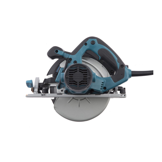
ONCEPT AND MAIN APPLICATIONS
Models HS7100, HS7101 have been developed as the successor models of
the current model 5705R, featuring compact & lightweight design without
riving knife.
Other features are:
• New aesthetic design with black blade case and rear cover
• Electronic brake for quick blade stop (for HS7101 only)
• Twin LED job light for easy tracing of cutting line in the dark place
(for HS7101 only)
These models are also available with plastic carrying case as "K" models;
HS7100K, HS7101K.
S
pecification
Voltage (V)
110
220 - 240
Specifications
Size of blade: mm (")
No load speed: rpm= min.
Max cutting capacity: mm (")
Protection against electric shock
Electric brake
Job light
Power supply cord: m (ft)
Weight according to
EPTA-Procedure 2003/01*
*1: with TCT saw blade, Dust nozzle
S
tandard equipment
TCT saw blade 190 ............. 1
Hex wrench ........................ 1
Guide rule (Rip fence) ....... 1
Dust nozzle ......................... 1
Guide rail adapter ............... 1 (for some countries only)
Note: The standard equipment for the tools shown above may vary by country.
O
ptional accessories
Saw blades
Guide rail 1400 set
Guide rail 1900 set
Guide rail 3000 set
HS7100, HS7101
Circular Saw 190mm (7-1/2")
Current (A)
Cycle (Hz)
13
50/60
6.4
50/60
Model No.
Diameter
Hole diameter
¹
ˉ
0 degree
45 degrees
50 degrees
: kg (lbs)
1
Position seat sets
Rubber seat set
Seat set
Guide rail adapter
Continuous Rating (W)
Input
1,400
1,400
HS7100
No
No
European countries: 4.0 (13.1), Australia, Brazil: 2.0 (6.6)
Other countries: 2.5 (8.2)
4.0 (8.8)
Bevel guide set
Guide rule (Rip fence)
Clamp set
Stopper
L
Dimensions: mm (")
Length (L)
Width (W)
Height (H)
Max. Output (W)
Output
680
640
HS7101
190 (7-1/2)
30 (1-3/16)
5,500
67.0 (2-5/8)
48.5 (1-15/16)
43.5 (1-11/16)
Double insulation
Yes
Yes (twin LED)
4.0 (8.9)
PRODUCT
P 1/16
H
W
310 (12-1/4)
246 (9-11/16)
258 (10-1/8)
1,750
2,200
Advertisement

Related Manuals for Makita HS7100K


Summary of Contents for Makita HS7100K
- Page 1 310 (12-1/4) (for HS7101 only) Width (W) 246 (9-11/16) These models are also available with plastic carrying case as “K” models; Height (H) 258 (10-1/8) HS7100K, HS7101K. pecification Continuous Rating (W) Voltage (V) Current (A) Cycle (Hz) Max. Output (W)
-
Page 2: Necessary Repairing Tools
Portion to lubricate Amount Blade case Gear room approx. 6 g Bearing box Drum portion where Safety cover pivots a little Angular guide Contact surface where (39) Blade case pivots a little Fig. 1 Makita Grease SG No.0 VG100 Safety cover... - Page 3 P 3/16 epair [3] DISASSEMBLY/ASSEMBLY [3] -1. Base DISASSEMBLING Set the cutting depth of the machine to maximum, and remove saw blade. Then remove both Rear angular guide section and Angular guide section from Base. Base can now be replaced. (Fig. 2) Fig.
- Page 4 P 4/16 epair [3] DISASSEMBLY/ASSEMBLY [3] -1. Base ASSEMBLING Base can be mounted to the machine by taking the reverse steps of Disassembling. Note: Follow the important instructions described in Fig. 2A. See Fig. 3 for Assembling and Adjustment of Lock lever for clamping Guide Rule. Fig.
- Page 5 P 5/16 epair [3] DISASSEMBLY/ASSEMBLY [3] -3. Depth Guide DISASSEMBLING Disassemble Depth guide as described in Fig. 4. Fig. 4 1. Set the cutting depth of the machine to minimum. 2. From M6x18 Hex bolt, remove Lever 70, M6 Hex nut, Remove Lock plate from Lever 70 by unscrewing Flat washer 6 and Sleeve 6.
- Page 6 P 6/16 epair [3] DISASSEMBLY/ASSEMBLY [3] -3. Depth Guide ASSEMBLING Assemble Depth guide section by taking the reverse step of Disassembling. (Fig. 4) Note: Follow the important instructions described in Fig. 5. Fig. 5 1. M6x18 Hex bolt must be mounted to Blade case so that the concave surface of the bolt head faces M5x8 Hex socket set screw.
- Page 7 P 7/16 epair [3] DISASSEMBLY/ASSEMBLY [3] -4. Angular Guide DISASSEMBLING Angular guide can be disassembled as described in Fig. 6. Fig. 6 1. Loosen M6x20 Hex bolt 2. Remove M6x20 Hex bolt 3. Loosen M6x8 Hex socket head set crew, with Lever 45, then remove by using Lever 45 as a tool, then remove Shoulder pin 6-7 that...
- Page 8 P 8/16 epair [3] DISASSEMBLY/ASSEMBLY [3] -5. Blade Case, Blade Cover, Safety Cover DISASSEMBLING (1) Separate Motor housing and Armature from Blade case section as described in Fig. 7. Fig. 7 1. Remove Carbon brush. 2. Remove three M5x45 Pan head screws. Brush holder Brush holder Carbon brush...
- Page 9 P 9/16 epair [3] DISASSEMBLY/ASSEMBLY [3] -5. Blade Case, Blade Cover, Safety Cover DISASSEMBLING (5) Remove Blade cover as described in Fig. 9. Fig. 9 1. Remove two M4x12 2. Grab Blade cover at the tab and the bottom 3. Pull off Blade cover from Pan head screws.
- Page 10 P 10/16 epair [3] DISASSEMBLY/ASSEMBLY [3] -6. Helical Gear, Ball Bearing 6003DDW DISASSEMBLING (1) Remove Safety cover, then remove Bearing box from Blade case. (Fig. 8) Then separate Helical gear together with Spindle from Bearing box as described in Fig. 11. Fig.
- Page 11 P 11/16 epair [3] DISASSEMBLY/ASSEMBLY [3] -7. Handle Cover, Electrical Parts in Handle DISASSEMBLING Remove Handle cover from Motor housing as described in Fig. 14. Note: No need to disassemble Blade case or Motor housing. Fig. 14 1. Lift up Handle cover 2.
- Page 12 P 12/16 epair [4] ADJUSTMENT [4]-2 Parallel Adjustment of Base to Saw Blade (1) Attach saw blade to the unplugged machine, and set the cutting depth of the machine to maximum with the bevel angle adjusted to 90 degrees. (2) Make parallel adjustment of Base to saw blade as described in Fig. 16. Fig.
-
Page 13: Circuit Diagram
P 13/16 ircuit diagram Fig. D-1 HS6100 & HS7100 (without Electric brake and LED light) Color index of lead wires' sheath Blue Black White Brown Brush Brush holder R holder F Switch Field Brush Brush holder R holder F Field, viewed from Noise suppressor Blade case side... -
Page 14: Wiring Diagram
P 14/16 iring diagram Fig. D-2 HS6100 & HS7100 (without Electric brake and LED light) Be careful not to put Lead wire (blue or white) Route Field lead wires of Power supply cord on Noise suppressor into Handle section Field lead wires must be after connecting it to Terminal block. - Page 15 P 15/16 ircuit diagram Fig. D-3 HS6101 & HS7101 (with Electric brake and LED light) Color index of lead wires' sheath Black Blue Brown Orange Purple White Yellow Brush Brush holder R holder F Switch Field Brush Choke coil Brush holder R holder F Field,...
- Page 16 P 16/16 iring diagram Fig. D-4 HS6101 & HS7101 (with Electric brake and LED light) Be careful not to put Route Field lead wires and Fix Lead wires of Lead wires of LED Light circuit LED Light circuit Lead wire (blue or white) into Handle section through in this Lead wire of Power supply cord...