Table of Contents
Advertisement
Quick Links
OPERATOR'S MANUAL
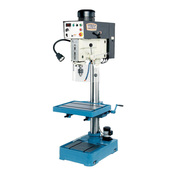
VARIABLE SPEED DRILL PRESS
REPRODUCTION OF THIS MANUAL IN ANY FORM WITHOUT WRITTEN APPROVAL OF BAILEIGH INDUSTRIAL
HOLDINGS LLC IS PROHIBITED. Baileigh Industrial Holdings LLC, Inc. does not assume and hereby disclaims any
liability for any damage or loss caused by an omission or error in this Operator's Manual, resulting from accident,
negligence, or other occurrence.
MODEL: DP-1250VS
Baileigh Industrial Holdings LLC
P.O. Box 531
Manitowoc, WI 54221-0531
Phone: 920.684.4990
Fax: 920.684.3944
sales@baileigh.com
© 2020 Baileigh Industrial Holdings LLC
Rev. 08/2020
Advertisement
Table of Contents

Related Manuals for Baileigh DP-1250VS


Summary of Contents for Baileigh DP-1250VS
- Page 1 REPRODUCTION OF THIS MANUAL IN ANY FORM WITHOUT WRITTEN APPROVAL OF BAILEIGH INDUSTRIAL HOLDINGS LLC IS PROHIBITED. Baileigh Industrial Holdings LLC, Inc. does not assume and hereby disclaims any liability for any damage or loss caused by an omission or error in this Operator’s Manual, resulting from accident, negligence, or other occurrence.
-
Page 2: Table Of Contents
Table of Contents THANK YOU & WARRANTY ..................1 INTRODUCTION ......................3 GENERAL NOTES ......................3 SAFETY INSTRUCTIONS ....................4 SAFETY PRECAUTIONS ....................7 Dear Valued Customer: ....................7 TECHNICAL SPECIFICATIONS ................... 10 TECHNICAL SUPPORT ....................11 UNPACKING AND CHECKING CONTENTS ..............12 TRANSPORTING AND LIFTING .................. - Page 3 Electrical Component Parts List ................. 48 Electrical Enclosure Components ................49 TROUBLESHOOTING ....................50 Troubleshooting the Inverter ..................51...
-
Page 4: Thank You & Warranty
THANK YOU & WARRANTY Thank you for your purchase of a machine from Baileigh Industrial Holdings LLC. We hope that you find it productive and useful to you for a long time to come. Inspection & Acceptance. Buyer shall inspect all Goods within ten (10) days after receipt thereof. Buyer’s payment shall constitute final acceptance of the Goods and shall act as a waiver of the Buyer’s rights to inspect or... - Page 5 We apologize for any discrepancies that may occur. Baileigh Industrial Holdings LLC reserves the right to make any and all changes deemed necessary in the course of business including but not limited to pricing, product specifications, quantities, and product availability.
-
Page 6: Introduction
INTRODUCTION The quality and reliability of the components assembled on a Baileigh Industrial Holdings LLC machine guarantee near perfect functioning, free from problems, even under the most demanding working conditions. However, if a situation arises, refer to the manual first. If a solution cannot be found, contact the distributor where you purchased our product. -
Page 7: Safety Instructions
IMPORTANT PLEASE READ THIS OPERATORS MANUAL CAREFULLY It contains important safety information, instructions, and necessary operating procedures. The continual observance of these procedures will help increase your production and extend the life of the equipment. SAFETY INSTRUCTIONS LEARN TO RECOGNIZE SAFETY INFORMATION This is the safety alert symbol. - Page 8 SAVE THESE INSTRUCTIONS. Refer to them often and use them to instruct others. PROTECT EYES Wear safety glasses or suitable eye protection when working on or around machinery. PROTECT AGAINST NOISE Prolonged exposure to loud noise can cause impairment or loss of hearing.
- Page 9 ENTANGLEMENT HAZARD – ROTATING SPINDLE Contain long hair, DO NOT wear jewelry or loose fitting clothing. EMERGENCY STOP BUTTON In the event of incorrect operation or dangerous conditions, the machine can be stopped immediately by pressing the E-STOP button. Twist the emergency stop button clockwise (cw) to reset. Note: Resetting the E-Stop will not start the machine.
-
Page 10: Safety Precautions
Baileigh does not recommend or endorse making any modifications or alterations to a Baileigh machine. Modifications or alterations to a machine may pose a substantial risk of injury to the operator or others and may do substantial damage to the machine. - Page 11 8. Do not force tool. Your machine will do a better and safer job if used as intended. DO NOT use inappropriate attachments in an attempt to exceed the machine’s rated capacity. 9. Use the right tool for the job. DO NOT attempt to force a small tool or attachment to do the work of a large industrial tool.
- Page 12 Additional Safety Precautions • Turn off main power to the machine and wait for the drill bit, or cutting tool to stop turning before removing debris, removing or securing the piece part, or changing the position of the work table. •...
-
Page 13: Technical Specifications
TECHNICAL SPECIFICATIONS Motor and Electricals: Power Input Requirements 220V, 1Ph, 60hz Motor Type TEFC Induction 2HP (1.5kw), 220V, 3ph, 60hz, 6.6A, Motor Power 1720rpm Starting Amps 9.2A Running Amps (No Load) 1.7A Inverter M-Type Power Cable 14awg, 6 Ft Power Plug Not included Recommended Circuit and Fuse/Breaker Size 20A Sound Emission Without Load... -
Page 14: Technical Support
(other than die sets and blades). For specific application needs or future machine purchases contact the Sales Department at: sales@baileigh.com, Phone: 920.684.4990, or Fax: 920.684.3944. Note: The photos and illustrations used in this manual are representative only and may not depict the actual color, labeling or accessories and may be intended to illustrate technique only. -
Page 15: Unpacking And Checking Contents
UNPACKING AND CHECKING CONTENTS Your Baileigh machine is shipped complete. Separate all parts from the packing material and check each item carefully. Make certain all items are accounted for before discarding any packing material. WARNING: SUFFOCATION HAZARD! Immediately discard any plastic bags and packing materials to eliminate choking and suffocation hazards to children and animals. -
Page 16: Transporting And Lifting
TRANSPORTING AND LIFTING NOTICE: Lifting and carrying operations should be carried out by skilled workers, such as a truck operator, crane operator, etc. If a crane is used to lift the machine, attach the lifting chain carefully, making sure the machine is well balanced. Follow these guidelines when lifting with truck or trolley: •... -
Page 17: Installation
• Use lift equipment such as straps, chains, capable of lifting 1.5 to 2 times the weight of the machine. • Take proper precautions for handling and lifting. • Check if the load is properly balanced by lifting it an inch or two. •... -
Page 18: Anchoring The Machine
• POWER SUPPLY PLACEMENT: The power supply should be located close enough to the machine so that the power cord is not in an area where it would cause a tripping hazard. Be sure to observe all electrical codes if installing new circuits and/or outlets. Anchoring the Machine •... -
Page 19: Getting To Know Your Machine
GETTING TO KNOW YOUR MACHINE... - Page 20 Motor Provides power to the chuck Changes spindle speed RPM. DO NOT change spindle 2-Speed Hi-Lo RPM until the spindle has stopped completely Electrical Enclosure Houses the electrical components Houses the operator’s controls Control Panel Down-Feed Handle Used by the operator to move the quill down and up. Column Supports the table and head Gear Rack...
- Page 21 Limit Switch Stops machine when guard is swung away Spring Cover Tensions down-feed handles (DO NOT REMOVE) Guard Knob Use to hold guard after pivoting sideways Guard Adjustment Knob Change guard height and lock with knob DIGITAL INDICATOR 245-2000 65-540 Coolant Pump On/Off Switch Starts the coolant flow for cutting.
- Page 22 High / Low Gear Selector A gear transmission lever that selects Hi or Low speeds. IMPORTANT: Use only while the machine is stopped. Failure to do so will cause damage to the gear system. Drill Head The Drill Head attaches to the top of the column. It houses the motor, spindle, controls, and transfer mechanisms.
-
Page 23: Electrical
ELECTRICAL CAUTION: HAVE ELECTRICAL UTILITIES CONNECTED TO MACHINE BY A CERTIFIED ELECTRICIAN! Check if the available power supply is the same as listed on the machine nameplate. WARNING: Make sure the grounding wire (green) is properly connected to avoid electric shock. DO NOT switch the position of the green grounding wire if any electrical plug wires are switched during hookup. - Page 24 • Improper connection of the equipment-grounding conductor can result in risk of electric shock. The conductor with insulation having an outer surface that is green with or without yellow stripes is the equipment-grounding conductor. If repair or replacement of the electric cord or plug is necessary, do not connect the equipment-grounding conductor to a live terminal.
-
Page 25: Set Up And Adjustments
SET UP AND ADJUSTMENTS Adjusting the Machine Head Height WARNING: Failure to lock the collar can result in personal injury or damage to the machine. The machine head is lowered for shipping and must be raised before operating. 1. Unlock the table by turning crankshaft (K) counterclockwise (ccw). -
Page 26: Adjusting The Gear Rack Height
Adjusting the Gear Rack Height WARNING: Failure to lock the collar can result in personal injury or damage to the machine. To raise the table to an adequate working height requires raising of the column gear rack. 1. Lock the table by turning crankshaft (K) clockwise (cw). 2. -
Page 27: Operation
OPERATION CAUTION: Always wear proper eye protection with side shields, safety footwear, and leather gloves to protect from burrs and sharp edges. When handling large heavy materials make sure they are properly supported. Drilling 1. Load and secure the piece part to the table. 2. -
Page 28: Tapping
Tapping 1. Load and secure the piece part to the table. 2. Secure tapping tool in the chuck. 3. Unlock the table, adjust to the desired height, and relock the table. 4. Adjust the safety guard up or down as needed. 5. -
Page 29: Removing Tooling From Spindle
Removing Tooling From Spindle 1. Disconnect machine from the power source. 2. Place a piece of wood on the table for protection. 3. Position the worktable approximately 10” under the bit and lower the spindle about 6”. 4. Place the drift key (AM) into the slot (AN) of the quill and tap the end of the drift key with a hammer until the bit or chuck arbor falls out. -
Page 30: Drilling Recommendations
DRILLING RECOMMENDATIONS Drilling Speeds The speed of a drill is usually measured in terms of the rate at which the outer periphery of the tool moves in relation to the work being drilled. The common term for this is Surface Feet per Minute (SFM). - Page 31 Speeds for High Speed Steel Drills Material Speed (SFPM) Alloy Steel — 300 to 400 Brinell 20-30 Stainless Steel 30-40 Automotive Steel Forgings 40-50 Tool Steel, 1.2C 50-60 Steel, .4C to .5C 70-80 Mild Machinery Steel, .2C to .3C 80-110 Hard Chilled Cast Iron 30-40 Medium Hard Cast Iron...
-
Page 32: Lubrication And Maintenance
LUBRICATION AND MAINTENANCE WARNING: Make sure the electrical disconnect is OFF before working on the machine. Maintenance should be performed on a regular basis by qualified personnel. Always follow proper safety precautions when working on or around any machinery. Daily Maintenance •... -
Page 33: Return Spring
Return Spring The spindle return is preset by the manufacturer and should not need adjustment. If future attention is ever required, proceed as follows: 1. Do NOT remove spring cap. 2. Loosen screw (A) just enough to rotate spring cap (B) past pin (Inside case. -
Page 34: Greasing The Machine
• Re-fill tank with coolant solution. Oils for Lubricating Coolant Any 10:1 (water to coolant) solution will work, however we recommend Baileigh B-Cool 20:1 (water to coolant) biodegradable metal cutting fluid. It has excellent cooling and heat transfer characteristics, is non-flammable, and extends tool and machine life. Each gallon of concentrate makes 21 gallons of coolant. -
Page 35: Motor / Drive Belt Replacement
Motor / Drive Belt Replacement 1. Disconnect machine from power source. Disconnect electrical power to drill press to avoid possibility of inadvertent operation and exposure to potentially lethal voltage levels. Note: Prefer to the parts diagram as needed to aid in disassembly and assembly. 2. -
Page 36: Head, Motor, And Electrical Parts Diagram
HEAD, MOTOR, AND ELECTRICAL PARTS DIAGRAM... -
Page 38: Head, Motor, And Electrical Parts List
Head, Motor, and Electrical Parts List Description Qty. DP1250VS-A1 Head Body DP1250VS-A2 Oil Window S-30 DP1250VS-A3 Ball Bearing 6202z DP1250VS-A4 C-Clip S-31 DP1250VS-A5 Gear M=2, T=32 DP1250VS-A6 Key 6x20 DP1250VS-A7 Drive Shaft M=2, T=13 DP1250VS-A8 Ball Bearing 6007z DP1250VS-A9 C-Clip R-62 DP1250VS-A10 Ball Bearing 6002z DP1250VS-A11... - Page 39 Description Qty. DP1250VS-A42 Hex Socket Capscrew M8x35 DP1250VS-A43 Oil Seal 25x5 DP1250VS-A44 Oil Seal 47x25x8 DP1250VS-A45 Set Screw M8x8 DP1250VS-A46 Drive Pulley DP1250VS-A49 Ball Bearing 6202z DP1250VS-A52 Key 6x20 DP1250VS-A54 Washer M8 DP1250VS-A55 Hex Socket Cap Screw M8x25 DP1250VS-A56 SB1, Emergency Stop Switch DP1250VS-A57 SB2, Stop Switch DP1250VS-A58...
- Page 40 Description Qty. DP1250VS-A87 Terminal Plate DP1250VS-A88 Aluminum Rail Plate DP1250VS-A89 KM2, Contactor DP1250VS-A90 KR, Relay DP1250VS-91 Q1, Main Disconnect Switch Assembly 1 DP1250VS-A93 Aluminum Rail Plate-Small Set Screw 1/4”x1/4” DP1250VS-A94 DP1250VS-A95 Cross Head Screw M3x16 DP1250VS-A96 QS2, QS3, Micro Switch DP1250VS-A97 Micro Switch Bracket DP1250VS-A98...
- Page 41 Description Qty. DP1250VS-A126 Screw M4x20 DP1250VS-A127 Terminal Plate DP1250VS-A128 Screw M4x8 DP1250VS-129 Safety Switch Bracket DP1250VS-A130 KM1, Contactor Washer 1/8” DP1250VS-A131 DP1250VS-A132 Oil Ring P-11 DP1250VS-A133 Tube DP1250VS-A134 C-Clip R-47 DP1250VS-A135 Hex Socket Cap Screw M8x12 DP1250VS-A136 Washer M5 DP1250VS-A137 Bearing Support DP1250VS-A138 Flat Head Screw 5x12...
-
Page 42: Head And Spindle Parts Diagram
HEAD AND SPINDLE PARTS DIAGRAM... -
Page 43: Head And Spindle Parts List
Head and Spindle Parts List Item Part No. Description Qty. DP1250VS-B1 Head Body DP1250VS-B2 Head Body Hex Bolt DP1250VS-B2-1 Spring DP1250VS-B3 Bushing DP1250VS-B4 DP1250VS-B5 Handle Set Screw 5/16”X3/4” DP1250VS-B7 DP1250VS-B8 Star Washer DP1250VS-B9 Spindle Nut DP1250VS-B10 Spindle Taper Sleeve DP1250VS-B11 Ball Bearing 6009zz DP1250VS-B12 Bearing Spacer... - Page 44 Item Part No. Description Qty. DP1250VS-B44 Bearing Cap 72.45.10 DP1250VS-45 Hex Nut DP1250VS-B46 Scale Rod DP1250VS-B48 Lock Nut DP1250VS-B49 Support Base DP1250VS-B50 Set Knob DP1250VS-B51 Pin 3x15 DP1250VS-B53 Face Plate Screw 3/16”X5/16” DP1250VS-B58 DP1250VS-B60 Depth Scale Bracket Set Screw 3/16”X1/2” DP1250VS-B61 DP1250VS-B62 Key 7x20...
-
Page 45: Column, Table, And Base Parts Diagram
COLUMN, TABLE, AND BASE PARTS DIAGRAM... -
Page 46: Column, Table, And Base Parts List
Column, Table, and Base Parts List Item Part No. Description Qty. DP1250VS-C1 Coolant Base DP1250VS-C2 Cover DP1250VS-3 M2, Coolant Pump 1/8HP, 230V Screw W/Washer 1/4” DP1250VS-C4 Cross Screw 1/4”X1/2” DP1250VS-C5 DP1250VS-C6 Support Bearing Collar Set Screw 3/8”X5/16” DP1250VS-C7 Brass Block 3/8” DP1250VS-C7-1 DP1250VS-C8 Steel Ball M10... - Page 47 DP1250VS-C31 Key 4x4x20 DP1250VS-C32 Gear DP1250VS-C33 Worm Gear DP1250VS-D34 Lock Sleeve DP1250VS-D35 Lock Sleeve (Thread) 35-1 DP1250VS-D35-1 Spring 35-2 DP1250VS-D35-2 Hex Socket Cap Screw M6x25 35-3 DP1250VS-D35-3 Spring Pin 5x20 DP1250VS-C36 Lift Handle Crank DP1250VS-C37 Table Connector 3/8” 37-1 DP1250VS-C37-1 DP1250VS-C38 Column DP1250VS-C39...
-
Page 48: Chuck Guard Part Diagram
CHUCK GUARD PART DIAGRAM... -
Page 49: Chuck Guard Parts List
Chuck Guard Parts List Item Part No. Description Qty. DP15VSF-G1 Spring Pin, 3x16mm DP15VSF-G2 Support Bracket Bar DP15VSF-G3 Bushing DP15VSF-G4 Spacer DP15VSF-G5 Rachet Lock Handle M6x20 DP15VSF-G6 C-Clip S30 DP15VSF-G7 Bracket DP15VSF-G8 Safety Shield, Lexan 410x210mm DP15VSF-G9 Lower Bracket Bar DP15VSF-G10 Hex Socket Head Cap Screw M8x12 DP15VSF-G11... -
Page 50: Electrical Schematic
ELECTRICAL SCHEMATIC VFD-B 200W 220V... -
Page 51: Electrical Component Parts List
Electrical Component Parts List Item Description Data Main Disconnect Switch 500VAC,16A,60Hz Fuses 500V~10 x 38, 1A Fuses 500V~10 x 38, 1A Fuses 500V~10 x 38, 4A Coil 24V, 50/60 Hz, Ui=660V, AC1=25A, AC# Contactor 220V, 2.2KW, 380V, 4.0KW, 4<<a>> Coil 24V, 50/60 Hz, Ui=660V, AC1=25A, AC# Contactor 220V, 2.2KW, 380V, 4.0KW, 4<<a>>... -
Page 52: Electrical Enclosure Components
Electrical Enclosure Components... -
Page 53: Troubleshooting
TROUBLESHOOTING WARNING: Make sure the electrical disconnect is OFF before working on the machine. FAULT PROBABLE CAUSE REMEDY 1. Wrong voltage 1. Make sure the machine voltage matches the nameplate. 2. Emergency switch has been 2. Turn E-Stop switch clockwise (cw) pressed. -
Page 54: Troubleshooting The Inverter
4. Feed rate too slow. 3. Sharpen tool or replace. 5. Failure to use cutting oil or 4. Increase feed enough to clear coolant. chips. (on steel.) 5. Use cutting oil or coolant on steel. 1. No drill spot. 1. Center punch or center drill work piece. - Page 55 * Replace safety fuses. * Grounding or safety wire G.F.F * When the display continues to show issues. the same code, contact Baileigh Industrial at (920)684-4990 * Internal EEPROM can not be read or programmed. C.F1~3 or others * Current sensor error.
- Page 56 BAILEIGH INDUSTRIAL HOLDINGS LLC 1625 D , WI 54220 UFEK RIVE ANITOWOC : 920. 684. 4990 F : 920. 684. 3944 HONE www.baileigh.com BAILEIGH INDUSTRIAL HOLDINGS LTD. U WIFT OINT WIFT ALLEY NDUSTRIAL STATE UGBY , CV21 1QH U IDLANDS...