Table of Contents
Advertisement
OPERATOR'S MANUAL
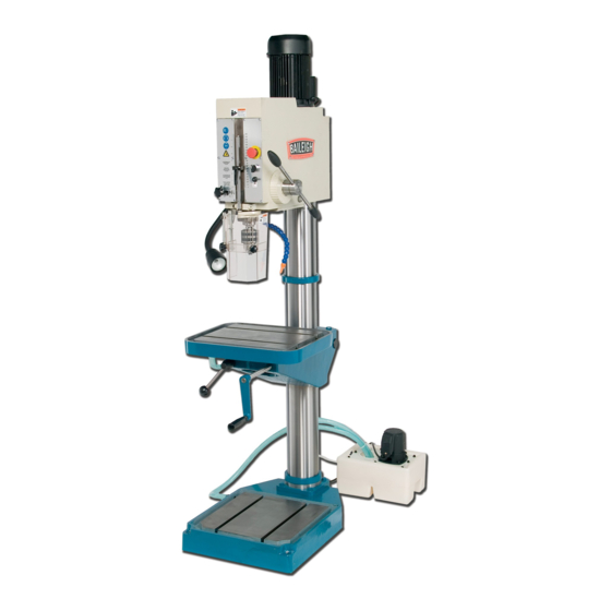
GEAR DRIVE DRILL PRESS
MODEL: DP-1500G
Baileigh Industrial, Inc.
P.O. Box 531
Manitowoc, WI 54221-0531
Phone: 920.684.4990
Fax: 920.684.3944
sales@baileighindustrial.com
REPRODUCTION OF THIS MANUAL IN ANY FORM WITHOUT WRITTEN APPROVAL OF BAILEIGH INDUSTRIAL, INC.
IS PROHIBITED. Baileigh Industrial, Inc. does not assume and hereby disclaims any liability for any damage or loss
caused by an omission or error in this Operator's Manual, resulting from accident, negligence, or other occurrence.
Rev. 02/2015
© 2015 Baileigh Industrial, Inc.
Advertisement
Table of Contents

Related Manuals for Baileigh DP-1500G


Summary of Contents for Baileigh DP-1500G
- Page 1 REPRODUCTION OF THIS MANUAL IN ANY FORM WITHOUT WRITTEN APPROVAL OF BAILEIGH INDUSTRIAL, INC. IS PROHIBITED. Baileigh Industrial, Inc. does not assume and hereby disclaims any liability for any damage or loss caused by an omission or error in this Operator’s Manual, resulting from accident, negligence, or other occurrence.
-
Page 2: Table Of Contents
Table of Contents THANK YOU & WARRANTY ..................1 INTRODUCTION ......................3 GENERAL NOTES ......................3 SAFETY INSTRUCTIONS ....................4 SAFETY PRECAUTIONS ....................6 TECHNICAL SPECIFICATIONS ..................8 TECHNICAL SUPPORT ....................8 UNPACKING AND CHECKING CONTENTS ..............9 Cleaning ........................9 TRANSPORTING AND LIFTING .................. -
Page 3: Thank You & Warranty
THANK YOU & WARRANTY Thank you for your purchase of a machine from Baileigh Industrial. We hope that you find it productive and useful to you for a long time to come. Inspection & Acceptance. Buyer shall inspect all Goods within ten (10) days after receipt thereof. Buyer’s payment shall constitute final acceptance of the Goods and shall act as a waiver of the Buyer’s rights to inspect or... - Page 4 Baileigh Industrial makes every effort to ensure that our posted specifications, images, pricing and product availability are as correct and timely as possible. We apologize for any discrepancies that may occur. Baileigh Industrial reserves the right to make any and all changes deemed necessary in the course of business including but not limited to pricing, product specifications, quantities, and product availability.
-
Page 5: Introduction
After receiving your equipment remove the protective container. Do a complete visual inspection, and if damage is noted, photograph it for insurance claims and contact your carrier at once, requesting inspection. Also contact Baileigh Industrial and inform them of the unexpected occurrence. Temporarily suspend installation. -
Page 6: Safety Instructions
IMPORTANT PLEASE READ THIS OPERATORS MANUAL CAREFULLY It contains important safety information, instructions, and necessary operating procedures. The continual observance of these procedures will help increase your production and extend the life of the equipment. SAFETY INSTRUCTIONS LEARN TO RECOGNIZE SAFETY INFORMATION This is the safety alert symbol. - Page 7 SAVE THESE INSTRUCTIONS. Refer to them often and use them to instruct others. PROTECT EYES Wear safety glasses or suitable eye protection when working on or around machinery. PROTECT AGAINST NOISE Prolonged exposure to loud noise can cause impairment or loss of hearing.
-
Page 8: Safety Precautions
SAFETY PRECAUTIONS Metal working can be dangerous if safe and proper operating procedures are not followed. As with all machinery, there are certain hazards involved with the operation of the product. Using the machine with respect and caution will considerably lessen the possibility of personal injury. However, if normal safety precautions are overlooked or ignored, personal injury to the operator may result. - Page 9 11. Do not overreach. Maintain proper footing and balance at all times. DO NOT reach over or across a running machine. 12. Stay alert. Watch what you are doing and use common sense. DO NOT operate any tool or machine when you are tired. 13.
-
Page 10: Technical Specifications
TECHNICAL SPECIFICATIONS Drill Capacity 1.5” (38.1mm) Tapping Capacity 1.3” (33mm) Spindle Speed (rpm) 108, 162, 240, 360, 528, 805, 1175, 1800 Spindle Taper MT 4 Spindle Travel 7.5” (190mm) Tables Dimensions (L x W) 20” x 16” (508 x 406mm) Table T-Slots .575”... -
Page 11: Unpacking And Checking Contents
UNPACKING AND CHECKING CONTENTS Your Baileigh machine is shipped complete in one crate. Separate all parts from the packing material and check each item carefully. Make certain all items are accounted for before discarding any packing material. WARNING: SUFFOCATION HAZARD! Immediately discard any plastic bags and packing materials to eliminate choking and suffocation hazards to children and animals. -
Page 12: Transporting And Lifting
TRANSPORTING AND LIFTING CAUTION: Lifting and carrying operations should be carried out by skilled workers, such as a truck operator, crane operator, etc. If a crane is used to lift the machine, attach the lifting chain carefully, making sure the machine is well balanced. -
Page 13: Installation
INSTALLATION IMPORTANT: Consider the following when looking for a suitable location to place the machine: • Overall weight of the machine. • Weight of material being processed. • Sizes of material to be processed through the machine. • Space needed for auxiliary stands, work tables, or other machinery. •... -
Page 14: Overall Dimensions
OVERALL DIMENSIONS ON OFF 19.75 (502) 38.00 (965) -
Page 15: Getting To Know Your Machine
GETTING TO KNOW YOUR MACHINE Cover Removed... - Page 16 Item Description Function Drill Motor Provides power to the chuck Head Assembly Houses the drive gears and supports the motor Electrical Enclosure Houses the electrical components and connections. Column Supports the table and head. Gear Rack Engages the table support arm for height adjustment. Coolant Pump Pumps cooling fluid up to the chuck and drilling area.
-
Page 17: Spindle Speed Knobs
Rocker (Item 65) Spindle Speed Knobs At 60Hz. the spindle speeds range from 108- 1800 rpm. Speeds are changed by turning the knobs (P) to the positions as shown in the chart. V/min U/min 1500 1175 1800 (Note: V/min and U/min mean RPM in other languages.) -
Page 18: The Drill Head
The Drill Head The drill head attaches to the top of the column. It supports the motor and spindle while housing the controls, gear transmission, and electrical components. Attached to it is the protective guard, the work light, and the coolant valve with nozzle. -
Page 19: Assembly And Set Up
ASSEMBLY AND SET UP WARNING: For your own safety, DO NOT connect the machine to the power source until the machine is completely assembled and you read and understand the entire instruction manual. 1. Carefully remove the crate. 2. Stand the machine upright. 3. -
Page 20: Electrical
ELECTRICAL WARNING: Baileigh Industrial is not responsible for any damage caused by wiring up to an alternative 3-phase power source other than direct 3-phase. If you are using an alternate power source, consult a certified electrician or contact Baileigh Industrial prior to energizing the machine. - Page 21 WARNING: In all cases, make certain the receptacle in question is properly grounded. If you are not sure, have a qualified electrician check the receptacle • Improper connection of the equipment-grounding conductor can result in risk of electric shock. The conductor with insulation having an outer surface that is green with or without yellow stripes is the equipment-grounding conductor.
-
Page 22: Operation
OPERATION CAUTION: Always wear proper eye protection with side shields. Restrain and contain long hair, loose or baggy clothing and remove jewelry to prevent entanglement. IMPORTANT: DO NOT change spindle RPM and or rotation direction until the spindle has stopped completely. This will damage the gears, voiding warranty. 1. -
Page 23: Automatic Drill Ejector
11. Repeat with above settings or make spindle speed and power feed changes as necessary. In the event of incorrect operation or dangerous conditions, the machine can be stopped immediately by pressing the E-STOP button. Twist the button clockwise (cw) to reset. Automatic Drill Ejector This machine is equipped with an automatic drill ejector. -
Page 24: Lubrication And Maintenance
LUBRICATION AND MAINTENANCE WARNING: Make sure the electrical disconnect is OFF before working on the machine. Maintenance should be performed on a regular basis by qualified personnel. Always follow proper safety precautions when working on or around any machinery. Daily Maintenance •... -
Page 25: Greasing The Machine
Greasing the Machine • Grease the gear rack on the column to keep the table moving smoothly. • Lubricate the spline of the spindle and the teeth of the rack with a #2 grease. • Fully extend the spindle and lightly grease the spindle shaft. -
Page 26: Oil Disposal
• Re-fill tank with coolant solution. Oils for Lubricating Coolant Any 10:1 (water to coolant) solution will work, however we recommend Baileigh B-Cool 20:1 (water to coolant) biodegradable metal cutting fluid. It has excellent cooling and heat transfer characteristics, is non-flammable, and extends tool and machine life. Each gallon of concentrate makes 21 gallons of coolant. -
Page 27: Parts Identification Drawing A
PARTS IDENTIFICATION DRAWING A... -
Page 28: Drill Head Parts List
Drill Head Parts List Item Part No. Description Detail 2Z02550 Pillar 3514542 Screw MC6S-12X50 3B01178 Washer BRB-13x24 2V02505 Spindle housing 4L02510 Covering plate 3S13447 Screw MC6S-8X20 2I04353 Rack FBB-5.1 3S03327 Screw MC6S-5X12 3B05146 Washer 2G02515 Spindle sleeve 4B03770 Grommet 3L51008 Taper roll bearing 30208 2N00535... - Page 29 Item Part No. Description Detail 28-6 2D20002 Spacing sleeve 20X2 28-7 3L11004 Ball bearing 6204 28-8 2N02508 Bearing housing 3P12314 FRP-5X32 3S03386 Screw MC6S-6X80 2X02640 4th shaft complete 31-1 2A02641 Shaft 31-2 2D20003 Spacing sleeve 20X3 31-3 3L11004 Ball bearing 6204 31-4 2H02646...
- Page 30 Item Part No. Description Detail 34-5 2T02607 34-6 2T04254 Clutch jaw 34-7 2H02613 Gear wheel 42-2 34-8 2H02626 Gear wheel 15-2 34-9 3K00187 5X20 34-10 3L15003 Ball bearing 6203 2X02610 1st Shaft complete 35-1 2A02611 Motor shaft extension 35-2 2D17003 Spacing sleeve 17x3 35-3...
- Page 31 Item Part No. Description Detail 3S22325 Screw MRX-5X10 2T02514 Cable duct 4L02509 Covering plate 3S11287 Screw FS-4X8 3C01147 Circlip SgA-60 2T02521 4L02511-5 Front plate left 4C02523 Spring 3P12373 FRP-8x16 4L02547 Rocker 4L02548 Plate 4L02512-5 Front plate right 3S03461 Screw MC6S 8X50 4L02513 2 Front plate S40...
-
Page 37: Parts Identification Drawing B
PARTS IDENTIFICATION DRAWING B... -
Page 38: Feed Gear Box B Parts List
Feed Gear Box B Parts List Item Part No. Description Detail 3C01134 Circlip SgA 36 4C00150 Spring 2B05235 Washer 2X02657 Worm gear, complete 2T02659 2B02539 Washer 2A02540 Piston 3R00023 Knob 3T04044 S1eelball 2I02538 Gear shaft 2X02571 Arm with ball joint 2T02541 Bushing 3S07453... - Page 39 Item Part No. Description Detail 3S50003 Screw R1/2" D908 3N03201 Rivet KDS-4X5 3C01119 Circlip SgA-17 2T05245 Spacing sleeve 2T05235 Shaft 3L11003 Bearing! 6203 2D17002 Spacing sleeve 17x2 2A02536 Shaft 3K00187 5x20 2H03230 Gear Wheel 38-1.5 2H05246 Gear Wheel 33-1.5 2H05247 Gear Wheel 27-1.5 2H05248...
-
Page 40: Parts Identification Drawing C
PARTS IDENTIFICATION DRAWING C... - Page 41 Table Arm Parts List Item Part. No. Description Detail 3R02003 Ball D-35 M-10 2E05035 2T05034 Locking Head 2Y02561 Table Arm 3S03497 Screw MC6S-10X35 2X02565 Locking Shaft, Complete 3S00018 Screw T6SS-10X16 3T08103 Plug D-47 2X02573 Gear Shaft, Complete 2I02562 Gear Shaft 2I04408 Worm Wheel 3K00227...
-
Page 42: Electrical Enclosure Components
ELECTRICAL ENCLOSURE COMPONENTS Item Name Specification Qty. Main Motor 220V, 3ph, 60hz Coolant Pump 1/8hp, 220V, 3ph, 50/60hz, L130, 4bolt, 3-9/16" 1 Current Breaker DZ47-63, C2 Transformer LBK5-60VA, PRI=110/220V, SEC=24V KM1, KM2 Contactor CU-11 E-Stop Button Heat Relay Drill Start/Stop ZB2-BE102C / ZB2-BE101C Coolant Start/Stop... -
Page 43: Electrical Schematic
ELECTRICAL SCHEMATIC... -
Page 44: Troubleshooting
TROUBLESHOOTING WARNING: Make sure the electrical disconnect is OFF before working on the machine. FAULT PROBABLE CAUSE REMEDY 1. Wrong voltage 1. Make sure the machine voltage matches the nameplate. 2. Emergency switch has been 2. Turn E-Stop switch clockwise Drill Press Does pressed. - Page 45 FAULT PROBABLE CAUSE REMEDY 1. No drill spot. 1. Center punch or center drill work piece. 2. Cutting lips on drill off center. 2. Regrind drill. Drill Leads Off 3. Quill loose in head. 3. Tighten quill. 4. Bearing play. 4.
- Page 46 NOTES...
- Page 47 NOTES...
- Page 48 , WI 54220 UFEK RIVE ANITOWOC : 920. 684. 4990 F : 920. 684. 3944 HONE www.baileigh.com BAILEIGH INDUSTRIAL, INC. 1455 S. C , CA 91761 AMPUS VENUE NTARIO : 920. 684. 4990 F : 920. 684. 3944 HONE BAILEIGH INDUSTRIAL LTD. U...