Table of Contents
Advertisement
OPERATOR'S MANUAL
HIGH SPEED VARIABLE SPEED DRILL PRESS
MODEL: DP-1250VS-HS
Baileigh Industrial, Inc.
P.O. Box 531
Manitowoc, WI 54221-0531
Phone: 920.684.4990
Fax: 920.684.3944
sales@baileighindustrial.com
REPRODUCTION OF THIS MANUAL IN ANY FORM WITHOUT WRITTEN APPROVAL OF BAILEIGH INDUSTRIAL, INC.
IS PROHIBITED. Baileigh Industrial, Inc. does not assume and hereby disclaims any liability for any damage or loss
caused by an omission or error in this Operator's Manual, resulting from accident, negligence, or other occurrence.
Rev. 03/2015
© 2015 Baileigh Industrial, Inc.
Advertisement
Table of Contents

Related Manuals for Baileigh DP-1250VS-HS


Summary of Contents for Baileigh DP-1250VS-HS
- Page 1 REPRODUCTION OF THIS MANUAL IN ANY FORM WITHOUT WRITTEN APPROVAL OF BAILEIGH INDUSTRIAL, INC. IS PROHIBITED. Baileigh Industrial, Inc. does not assume and hereby disclaims any liability for any damage or loss caused by an omission or error in this Operator’s Manual, resulting from accident, negligence, or other occurrence.
-
Page 2: Table Of Contents
Table of Contents THANK YOU & WARRANTY ..................1 INTRODUCTION ......................3 GENERAL NOTES ......................3 SAFETY INSTRUCTIONS ....................4 SAFETY PRECAUTIONS ....................6 TECHNICAL SPECIFICATIONS ..................9 TECHNICAL SUPPORT ....................9 UNPACKING AND CHECKING CONTENTS ..............10 Cleaning ........................10 TRANSPORTING AND LIFTING .................. - Page 3 Electrical Component Parts List ................. 43 Electrical Enclosure Components ................44 TROUBLESHOOTING ....................45 Troubleshooting the Inverter ..................46...
-
Page 4: Thank You & Warranty
THANK YOU & WARRANTY Thank you for your purchase of a machine from Baileigh Industrial. We hope that you find it productive and useful to you for a long time to come. Inspection & Acceptance. Buyer shall inspect all Goods within ten (10) days after receipt thereof. Buyer’s payment shall constitute final acceptance of the Goods and shall act as a waiver of the Buyer’s rights to inspect or... - Page 5 Baileigh Industrial makes every effort to ensure that our posted specifications, images, pricing and product availability are as correct and timely as possible. We apologize for any discrepancies that may occur. Baileigh Industrial reserves the right to make any and all changes deemed necessary in the course of business including but not limited to pricing, product specifications, quantities, and product availability.
-
Page 6: Introduction
After receiving your equipment remove the protective container. Do a complete visual inspection, and if damage is noted, photograph it for insurance claims and contact your carrier at once, requesting inspection. Also contact Baileigh Industrial and inform them of the unexpected occurrence. Temporarily suspend installation. -
Page 7: Safety Instructions
IMPORTANT PLEASE READ THIS OPERATORS MANUAL CAREFULLY It contains important safety information, instructions, and necessary operating procedures. The continual observance of these procedures will help increase your production and extend the life of the equipment. SAFETY INSTRUCTIONS LEARN TO RECOGNIZE SAFETY INFORMATION This is the safety alert symbol. - Page 8 SAVE THESE INSTRUCTIONS. Refer to them often and use them to instruct others. PROTECT EYES Wear safety glasses or suitable eye protection when working on or around machinery. PROTECT AGAINST NOISE Prolonged exposure to loud noise can cause impairment or loss of hearing.
-
Page 9: Safety Precautions
EMERGENCY STOP BUTTON In the event of incorrect operation or dangerous conditions, the machine can be stopped immediately by pressing the E-STOP button. Twist the emergency stop button clockwise (cw) to reset. Note: Resetting the E-Stop will not start the machine. SAFETY PRECAUTIONS Metal working can be dangerous if safe and proper operating procedures are not followed. - Page 10 8. Use the right tool for the job. DO NOT attempt to force a small tool or attachment to do the work of a large industrial tool. DO NOT use a tool for a purpose for which it was not intended.
- Page 11 Additional Safety Precautions • Turn off main power to the machine and wait for the drill bit, or cutting tool to stop turning before removing debris, removing or securing the piece part, or changing the position of the work table. •...
-
Page 12: Technical Specifications
TECHNICAL SPECIFICATIONS Table Size 22" x 18.5" (560 x 470mm) Quill Diameter 2.95" (75mm) Spindle Nose to Table 36.41" (925mm) Spindle Nose to Base 48.22" (1225mm) Spindle Speed High 375 – 4000 rpm Spindle Speed Low 100 – 1070 rpm Spindle Taper MT3 / MT4 optional Table Slot... -
Page 13: Unpacking And Checking Contents
UNPACKING AND CHECKING CONTENTS Your Baileigh machine is shipped complete in one crate. Separate all parts from the packing material and check each item carefully. Make certain all items are accounted for before discarding any packing material. WARNING: SUFFOCATION HAZARD! Immediately discard any plastic bags and packing materials to eliminate choking and suffocation hazards to children and animals. -
Page 14: Transporting And Lifting
TRANSPORTING AND LIFTING IMPORTANT: Lifting and carrying operations should be carried out by skilled workers, such as a truck operator, crane operator, etc. If a crane is used to lift the machine, attach the lifting chain carefully, making sure the machine is well balanced. Follow these guidelines when lifting with truck or trolley: •... -
Page 15: Installation
• Use lift equipment such as straps, chains, capable of lifting 1.5 to 2 times the weight of the machine. • Take proper precautions for handling and lifting. • Check if the load is properly balanced by lifting it an inch or two. •... -
Page 16: Anchoring The Machine
• POWER SUPPLY PLACEMENT: The power supply should be located close enough to the machine so that the power cord is not in an area where it would cause a tripping hazard. Be sure to observe all electrical codes if installing new circuits and/or outlets. Anchoring the Machine •... -
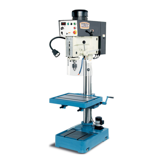
Page 17: Getting To Know Your Machine
GETTING TO KNOW YOUR MACHINE... - Page 18 Motor Provides power to the chuck Changes spindle speed RPM. DO NOT change spindle 2-Speed Hi-Lo RPM until the spindle has stopped completely Electrical Enclosure Houses the electrical components Control Panel Houses the operators controls Down-Feed Handle Changes down-feed from Auto to Manual Column Supports the table and head Gear Rack...
- Page 19 Limit Switch Stops machine when guard is swung away Spring Cover Tensions down-feed handles (DO NOT REMOVE) Guard Knob Use to hold guard after pivoting sideways Guard Adjustment Knob Change guard height and lock with knob DIGITAL INDICATOR 375-4000 100-1070 Coolant Pump On/Off Switch Starts the coolant flow for cutting.
- Page 20 B - High / Low Gear Selector - A gear transmission lever that selects Hi or Low speeds. IMPORTANT: Use only while the machine is stopped. Failure to do so will cause damage to the gear system. Drill Head The Drill Head attaches to the top of the column. It houses the motor, spindle, controls, and transfer mechanisms.
-
Page 21: Electrical
ELECTRICAL CAUTION: HAVE ELECTRICAL UTILITIES CONNECTED TO MACHINE BY A CERTIFIED ELECTRICIAN! Check if the available power supply is the same as listed on the machine nameplate. WARNING: Make sure the grounding wire (green) is properly connected to avoid electric shock. DO NOT switch the position of the green grounding wire if any electrical plug wires are switched during hookup. -
Page 22: Plug Connection
• Improper connection of the equipment-grounding conductor can result in risk of electric shock. The conductor with insulation having an outer surface that is green with or without yellow stripes is the equipment-grounding conductor. If repair or replacement of the electric cord or plug is necessary, do not connect the equipment-grounding conductor to a live terminal. -
Page 23: Set Up And Adjustments
SET UP AND ADJUSTMENTS Adjusting the Machine Head Height WARNING: Failure to lock the collar can result in personal injury or damage to the machine. The machine head is lowered for shipping and must be raised before operating. 1. Unlock the table by turning crankshaft (K) counterclockwise (ccw). -
Page 24: Adjusting The Gear Rack Height
Adjusting the Gear Rack Height WARNING: Failure to lock the collar can result in personal injury or damage to the machine. To raise the table to an adequate working height requires raising of the column gear rack. 1. Lock the table by turning crankshaft (K) clockwise (cw). 2. -
Page 25: Operation
OPERATION CAUTION: Always wear proper eye protection with side shields, safety footwear, and leather gloves to protect from burrs and sharp edges. When handling large heavy materials make sure they are properly supported. Drilling 1. Load and secure the piece part to the table. 2. -
Page 26: Tapping
Tapping 1. Load and secure the piece part to the table. 2. Secure tapping tool in the chuck. 3. Unlock the table, adjust to the desired height, and relock the table. 4. Adjust the safety guard up or down as needed. 5. -
Page 27: Removing Tooling From Spindle
Removing Tooling From Spindle 1. Disconnect machine from the power source. 2. Place a piece of wood on the table for protection. 3. Position the work table approximately 10” under the bit and lower the spindle about 6”. 4. Place the drift key (AM) into the slot (AN) of the quill and tap the end of the drift key with a hammer until the bit or chuck arbor falls out. -
Page 28: Lubrication And Maintenance
LUBRICATION AND MAINTENANCE WARNING: Make sure the electrical disconnect is OFF before working on the machine. Maintenance should be performed on a regular basis by qualified personnel. Always follow proper safety precautions when working on or around any machinery. Daily Maintenance •... -
Page 29: Return Spring
If an adjustment becomes necessary, please contact a service representative at Baileigh Industrial. Ph: (920-684-4990) The figure at right shows the spring cap (A) which houses the spring and grip knob (B). -
Page 30: Greasing The Machine
• Re-fill tank with coolant solution. Oils for Lubricating Coolant Any 10:1 (water to coolant) solution will work, however we recommend Baileigh B-Cool 20:1 (water to coolant) biodegradable metal cutting fluid. It has excellent cooling and heat transfer characteristics, is non-flammable, and extends tool and machine life. Each gallon of concentrate makes 21 gallons of coolant. -
Page 31: Head, Motor, And Electrical Parts Diagram
HEAD, MOTOR, AND ELECTRICAL PARTS DIAGRAM... -
Page 33: Head, Motor, And Electrical Parts List
Head, Motor, and Electrical Parts List Description Size Qty. Head Body Oil Window S-30 Ball Bearing 6202z C-Clip S-31 Gear M=2,T=32 6x20 Drive Shaft M=2,T=13 Ball Bearing 6007z C-Clip R-62 Ball Bearing 6002z C-Clip S-25 Gear M=2,T=56 Gear M=2,T=36 6x20 7x55 Shaft 7x40... - Page 34 Description Size Qty. Hex Socket Capscrew M8x35 Oil Seal 25x5 Oil Seal 47x25x8 Set Screw M8x8 Drive Pulley Ball Bearing 6202z 6x20 Washer Hex Socket Cap Screw M8x25 Emergency Stop Switch Stop Switch Start Switch Selection Switch D/T Pump Switch Speed Control Knob Reversal Switch Screw...
- Page 35 Description Size Qty. Screw M4x20 Connecting Board Terminal Plate Aluminum Rail Plate Contactor Relay Safety Switch Assembly Relay Without CE Aluminum Rail Plate-Sm Set Screw 1/4”x1/4” Cross Head Screw M3x16 Micro Switch Micro Switch Bracket Micro Switch Support Rod Sensor Bracket Sensor Support Sensor Hex Socket Cap Screw...
- Page 36 Description Size Qty. Washer Hex Socket Cap Screw M8x12 Washer Screw M4x20 Terminal Plate Screw M4x8 Safety Switch Bracket Contactor For CE Mod. Washer 1/8” Oil Ring P-11 Tube C-Clip R-47 Hex Socket Cap Screw M8x12 Washer Bearing Support Flat Head Screw 5x12 Ball Bracket Speed Lever...
-
Page 37: Head And Spindle Parts Diagram
HEAD AND SPINDLE PARTS DIAGRAM... -
Page 38: Head And Spindle Parts List
Head and Spindle Parts List Description Size Qty. Head body Head body hex. bolt Spring Bushing Handle Set screw 5/16”x3/4” Star washer Spindle nut Spindle taper sleeve Ball bearing 6009zz Bearing spacer C-Clip S-45 Screw bushing Quill support pin Set knob Washer 25x2x1/4”... - Page 39 Description Size Qty. Option Bearing cap 72.45.10 Hex. nut Scale rod Lock nut Support base Set knob 3x15 Face plate Screw 3/16”x5/16” Depth scale bracket Set screw 3/16”x1/2” 7x20 Pinion shaft Flange Body handle Handle rod Sensor Screw M4x20 Knob Sensor Support Sensor Bracket Screw...
-
Page 40: Spindle Guard Parts Diagram
SPINDLE GUARD PARTS DIAGRAM... -
Page 41: Spindle Guard Parts List
Spindle Guard Parts List Description Size Qty. Roll Pin Vertical Position Bar Pivot Wedge Pin Ratchet Handle Lock Screw External Retaining Ring Mounting Block Plastic Guard Guard Mounting / Pivot Bar Socket Head Cap Screw Horizontal Extension Bar Lock Washer Lock Washer Socket Head Cap Screw Knob... -
Page 42: Column, Table, And Base Parts Diagram
COLUMN, TABLE, AND BASE PARTS DIAGRAM... -
Page 43: Column, Table, And Base Parts List
Column, Table, and Base Parts List Item Description Size Qty. Coolant base Cover Coolant pump 1/8HP,230V Coolant pump 1/8HP,460V Screw w/washer 1/4” Cross screw 1/4”x1/2” Support bearing collar Set screw 3/8”x5/16” Brass block 3/8” Steel ball Column bearing collar Spring pin 4x50 Crank shaft Spring pin... - Page 44 Item Description Size Qty. 35-1 Spring 35-2 Hex. socket cap screw M6x25 35-3 Spring pin 5x20 Lift handle crank Table 37-1 Connector 3/8” Column Handle Screw 40-1 Washer Clamping Cross cap screw 3/16”x3/8” Tube Connector Hex. socket cap screw M8x20 Support plate ON/OFF valve Nozzle...
-
Page 45: Electrical Schematic
ELECTRICAL SCHEMATIC VFD-B 200W 220V... -
Page 46: Electrical Component Parts List
Electrical Component Parts List Item Description Data Qty. Disconnecting Device 500VAC,16A,60Hz Fuses 500V~10 x 38 Fuses Fuses Coil 24V, 50/60 Hz Ui=660V, AC1=25A Contactor AC# 220V, 2.2KW 380V, 4.0KW , 4<<a>> Over Relay 0.3~0.45A Relay AC, 400V, 24V Transformer 52VA (1.2A) VFD-B Variable speed AC motor driver 460V, 4A, 230V, 7A, 1.5KW Braking resistors... -
Page 47: Electrical Enclosure Components
Electrical Enclosure Components... -
Page 48: Troubleshooting
TROUBLESHOOTING WARNING: Make sure the electrical disconnect is OFF before working on the machine. FAULT PROBABLE CAUSE REMEDY 1. Wrong voltage 1. Make sure the machine voltage matches the nameplate. 2. Emergency switch has been 2. Turn E-Stop switch clockwise (cw) pressed. -
Page 49: Troubleshooting The Inverter
4. Feed rate too slow. 3. Sharpen tool or replace. 5. Failure to use cutting oil or 4. Increase feed enough to clear coolant. chips. (on steel.) 5. Use cutting oil or coolant on steel. 1. No drill spot. 1. Center punch or center drill work piece. - Page 50 Code Error Description Solution * Check if motor voltage matches that * The voltage inverter detects of the voltage inverter. O.C. that the output current exceeds * Check connection between the the normal value. motor and the voltage inverter. * Check if the motor is overloaded. * The voltage inverter of the * Check if the circuit input voltage motor is detected with a D.C.
- Page 51 NOTES...
- Page 52 BAILEIGH INDUSTRIAL, INC. 1625 D , WI 54220 UFEK RIVE ANITOWOC : 920. 684. 4990 F : 920. 684. 3944 HONE www.baileigh.com BAILEIGH INDUSTRIAL LTD. U WIFT OINT WIFT ALLEY NDUSTRIAL STATE UGBY , CV21 1QH U IDLANDS NITED INGDOM...