
Related Manuals for R.V.R. Elettronica TEX1703


Summary of Contents for R.V.R. Elettronica TEX1703
- Page 1 TEX1703 TEX1703TFT USER MANUAL VOLUME1 Manufactured by R.V.R. ELETTRONICA Italia...
- Page 2 Limitations of use can apply in respect of operating freuency, transmitter power and/or channel spacing. Declaration of Conformity Hereby, R.V.R. Elettronica, declares that this FM transmitter is in complian- ce with the essential requirements and other relevant provisions of Directive 2014/53/EU.
- Page 3 TEX1703TFT Technical Specifications TEX1703TFT Parameters U.M. Value Notes GENERALS Frequency range 87,5 - 108 Rated output power 1700 Continuously variable by software from 0 to maximum Modulation type F300E Operational Mode Mono, Stereo, MPX Working temperature °C -5 to 60 Working Humidity 95 (Without condensing) Working Altitude...
- Page 4 TEX1703TFT AUDIO INPUTS Connector XLR F Type Balanced Left / Mono Impedance 10 k or 600 Selectable by rear panel dip switches Input Level /Adjust -12 to +12 continuosly variable Connector XLR F Type Balanced Right Impedance 10 k or 600 Selectable by rear panel dip switches Input Level -12 to +12...
-
Page 5: Table Of Contents
TEX1703TFT Table of Contents 1. Preliminary Instructions 2. Warranty 3. First aid 3.1 Treatment of electric shocks 3.2 Treatment of electrical burns 4. General description 4.1 Unpacking 4.2 Features 4.3 Description of the Front Panel 4.4 Description of the Rear Panel 4.5 Description of the Connectors 5. - Page 6 TEX1703TFT Quick guide 1. Turn on the switch on the front panel 2. Set the working frequency via the FRQ menu To change the value, simply use the + or - buttons and then confirm with ENTER or cancel with ESC (in mechanical key mode) or type the value directly on the display (in touchscreen mode).
-
Page 7: Preliminary Instructions
The product should not be incorporated into a rack unless retailers. it is provided with adequate ventilation or the manufacturer's if your retailer cannot help you, contact R.V.R. Elettronica instructions have been followed. and describe the issue; if the staff deems it necessary, the authorization to send the equipment will be sent to you with the appropriate instructions;... -
Page 8: First Aid
• Call a doctor as soon as possible. R.V.R. Elettronica 3.1.2 If the victim is conscious Via del Fonditore, 2/2c 40138 BOLOGNA ITALY •... -
Page 9: General Description
TEX1703TFT 4. General description The TEX1703TFT, produced by R.V.R. Elettronica, is acompact transmitter for frequency modulation broadcasting capable of transmitting in the 87.5 to 108 MHz band in 10kHz steps, with an adjustable RF output up to a maximum of 1700 W with a standard load of 50 Ohm. -
Page 10: Features
TEX1703TFT 4.2 Features The overall efficiency of the TEX1703TFT is over 70% over the entire band, which is why it is part of the RVR Green Line family. This performance characteristic is guaranteed in a range between + 0.25dB and -3 dB (+ 5% and -50%) with respect to the nominal power of the equipment: from 850W to 1785W for example in the case of the TEX1703TFT;... -
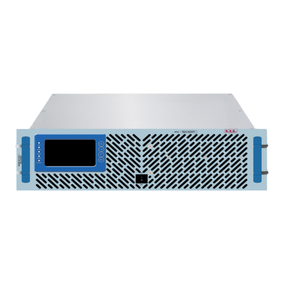
Page 11: Description Of The Front Panel
TEX1703TFT Five LEDs on the front panel provide the following status indications: ON, LOCK, FOLDBACK and RF MUTE. The exciter management firmware is based on a menu system. The user can navigate between the different submenus using the touchscreen or the four buttons: ESC, , and ENTER. -
Page 12: Description Of The Rear Panel
TEX1703TFT 4.4 Description of the Rear Panel PHASE RIGHT PUSH TO EXTRACT F1=F2 Fuses 10x38 10A T 16A T R.F. TEST 25A T -60dBc 10kΩ 600Ω 10kΩ 600Ω MAINS SCA1/RDS CARRIER FREQ.ADJ SCA2 19KHz PILOT LEFT/MONO EXT AGC R.F. RFL FWD F1=F2 REMOTE INTERLOCK... -
Page 13: Description Of The Connectors
TEX1703TFT [23] RFL EXT. AGC Trimmer for regulation of the limitation of delivered power according to the RFL fold input. [24] FWD EXT. AGC Trimmer for regulation of the limitation of delivered power according to the FWD fold input. [25] MODEM/LAN DB9 connector connected to the internal GSM modem (only with telemetry option) or RJ45 connector for TCP/IP communication (only with LAN option). -
Page 14: Installation And Configuration Procedure
TEX1703TFT 5. Installation and Configuration Procedure Instructions are given in this chapter on installation and configuration of the equipment. Carefully perform all the steps described in this chapter both upon initial start-up and every time the main configuration is changed, for example when moving to a new transmission station or when replacing the equipment. -
Page 15: Installation
TEX1703TFT 5.1 Installation 5.1.1 General Requirements The ventilation of the equipment and workplace must be suitable for maintenance according to the directive in force in the country in which this equipment is installed. To ensure correct operation of the appliance, there must be a clearance of at least 50 cm at the front and back of the device to facilitate the circulation of air through the ventilation grids. - Page 16 TEX1703TFT TEX1703TFT @ 230 Vac Main fuse (2x) F 16A type 6x30 Table 5.1: Fuses 5.1.2 Placement of the device Useful tips for correct installation: • Avoid the presence of external elements near the ventilation inlets and outlets, as they could prevent proper ventilation of the device. •...
- Page 17 TEX1703TFT The station normally has an air outlet at the rear of the equipment: in which case, ensure adequate ventilation of the room. COLD 50cm Alternatively it is cooled by forced ventilation and the air intake is located on the roof of the equipment.
- Page 18 TEX1703TFT It is strongly recommended to install the rack at least 50 cm from the rear and side walls in order to allow optimal air flow and ease of maintenance. 50cm 50cm 5.1.3 Power supply connections of the device Prepare the following connection (valid for both functional tests and final commissioning): √ Single-phase mains power connector, 230 (-15% / + 10%) Vac.
- Page 19 TEX1703TFT Note: to ensure both the safety of the operators and correct operation of the equipment, it is essential that the mains system is earthed and properly connected to the equipment. Useful tips for a correct connection: • Prepare suitable earthing of the electrical system. This offers both direct protection, as it prevents shocks when direct contact is made with the metal casings of the equipment, and indirect protection, as it cuts off the supply of energy when dispersion occurs due to poor insulation.
- Page 20 TEX1703TFT Obtain a 7/16” 50 Ohm RF cable for the connection between the Antenna and the device; the part that goes towards the device must be equipped with a 7/16” EIA connector. Connect the RF output of the transmitter to the antenna cable or to a dummy load capable of dissipating the power generated by the amplifier.
- Page 21 TEX1703TFT 5.1.5.2 Setting the working frequency Access the FRQ menu and use the touchscreen or keys to adjust the working frequency of the equipment. Press ENTER to confirm and wait for the LOCK LED to come on again. 5.1.5.3 Enabling the RF output If the power readings are zero, enable the RF output: •...
- Page 22 TEX1703TFT Input Sensitivity Notes SCA1/RDS - 9,2 ÷ +12 dBu Input level for 3,5 kHz overall deviation SCA2 - 9,2 ÷ +12 dBu (-30 dB) -12,5 ÷ +13,3 dBu Input level for 75 kHz overall deviation Left/Mono -12,7 ÷ +13,2 dBu (0 dB) Right -12,7 ÷...
-
Page 23: Management Firmware
TEX1703TFT 5.2 Management Firmware The device has a TFT touchscreen display, on which a set of menus are shown which indicate all the operating parameters of the product. To navigate the menus, use the touchscreen or the four mechanical keys that operate in the same way. - Page 24 TEX1703TFT Menu 1 NOTE: in power saving mode, the Menu key becomes ESC: press it to exit this mode. Pressing the ESC button (both in mechanical key and TouchScreen mode) while in the default menu (menu 1) opens the selection screen (menu 2), from which it is then possible to access all the other menus: Menu 2 To enter one of the menus, select the name with the + or - buttons (the selection is...
- Page 25 TEX1703TFT 5.2.2 Power Menu (PWR) This screen shows the user the parameters relating to the power delivery of the device. To edit one of the items, select it with the + or - buttons (the selected item is highlighted) and then press the ENTER button (both in mechanical key and TouchScreen mode).
- Page 26 TEX1703TFT 5.2.3 Frequency Menu (FRQ) This menu allows you to read and set the working frequency. To change the value, simply use the + or - buttons and then confirm with ENTER or cancel with ESC (in mechanical key mode) or type the value directly on the display (in touchscreen mode).
- Page 27 TEX1703TFT At any time it is possible to return to the selection screen(menu 2) by pressing the ESC button (both in mechanical key and TouchScreen mode) or after one minute of inactivity. Menu 5 Mode Selection of the audio coder mode between mono, stereo or composite mode.
- Page 28 TEX1703TFT 5.2.5 Amplifier Menu (PA) This menu allows you to read the parameters relating to the power amplifier. At any time it is possible to return to the selection screen (menu 2) by pressing the ESC button (both in mechanical key and TouchScreen mode) or after one minute of inactivity.
- Page 29 TEX1703TFT 5.2.6 Real Time Clock (RTC) menu This menu allows you to read and set the time and date of the device. To modify the value, simply use the + or - buttons and then confirm with ENTER or cancel with ESC (in mechanical key mode) or type the value directly on the display (in touchscreen mode).
- Page 30 TEX1703TFT 5.2.7 Frequency-shift keying (FSK) menu This menu provides the FSK (Frequency Shift Keying) adjustments of the exciter. To modify the value, simply use the + or - buttons and then confirm with ENTER or cancel with ESC (in mechanical key mode) or type the value directly on the display (in touchscreen mode).
- Page 31 TEX1703TFT Menu 10 Stat Enable (Remote) or disable (Local) the commands coming from remote. Stat Enables (x10) or disables (x1) the multiplication function of the instantaneous modulation reading. This display mode is useful when you want to view low levels of deviation. Adjustment of the Power Good threshold relating to the forward power.
- Page 32 TEX1703TFT 5.2.9 Version menu (Vrs) This screen shows information about the version of the device. At any time it is possible to return to the selection screen (menu 2) by pressing the ESC button (both in mechanical key and TouchScreen mode) or after one minute of inactivity.
-
Page 33: Identification And Access To The Modules
TEX1703TFT 6. Identification and Access to the Modules 6.1 Identification of the Modules The TEX1703TFT is composed of several modules which are interconnected with connectors to facilitate maintenance and replacement of the modules. 6.1.1 TEX1703TFT Top view The figure below shows the top view of the device, indicating the various components. - Page 34 TEX1703TFT 6.1.2 TEX1703TFT Bottom view The figure below shows the bottom view of the device, indicating the various components. figure 8.2 [1] Telemetry Card [2] Auxiliary Power Supply [3] Interface Card / 36 User Manual Rev. 1.0 - 27/05/21...
-
Page 35: Principles Of Operation
TEX1703TFT 7. Principles of Operation There is a schematic view of the modules and connections that make up the TEX1002 TFT in figure 7.1. R.F. R.F. 2 X R.F. 2 X R.F. R.F. OUTPUT LPF + SPLITTER DRIVER RF MODULES COMBINER DIRECT. -
Page 36: Telemetry Board
TEX1703TFT • Stereophonic coding • Mixing of mono, MPX and SCA channels • Clipper (limits the level of the modulating signal so that the frequency deviation does not exceed 75kHz) • Generation of the carrier of the modulated radiofrequency signal; •... -
Page 37: Bias Board
TEX1703TFT The amplification stage consists of two main blocks: • Amplification stage; • Low-pass filter, which also includes the power meter. In this block there is an RF pickup at approximately -46dB (for the TEX1703TFT model) with respect to the output available on a BNC connector below the transmitter output connector. -
Page 38: Maintenance And Repair Procedures
TEX1703TFT 8. Maintenance and Repair Procedures 8.1 Introduction This section gives general information on maintenance and electrical adjustments for the TEX1703TFT exciter. Maintenance is divided into two sections depending on the complexity of the procedure and the test equipment required to complete the maintenance. 8.2 Safety Considerations When the amplifier is operational, dangerous voltages, high currents, and strong RF signals are present inside. -
Page 39: Options
TEX1703TFT 9. Options This section shows views on the variants with respect to the basic version to be requested when ordering. For more information about the options, refer to the respective instruction manuals. 9.1 Option /AUDIGIN-TFT Digital Input Left (MONO) / Right Type: TOS-LINK Female Type: XLR Female 1 GND... -
Page 40: Option /Tlw-Tft-E-3He
TEX1703TFT Service/RDS Type: DB9 Female 1 GND 2 RS232 TX 3 RS232 RX 4 NC 5 GND 6 NC 7 NC 8 RDS CARRIER OUT 9 PILOT IN 9.3 Option /TLW-TFT-E-3HE Ethernet Type: RJ45 Female 1 TX+ 2 TX- 3 RX+ 4 NC 5 NC 6 RX-... -
Page 41: Option /Cnt7/8-150
TEX1703TFT 9.4 Option /CNT7/8-150 R.F. OUTPUT Type: 7/8”, 50Ω User Manual / 36 Rev. 1.0 - 27/05/21... - Page 42 TEX1703TFT This page was intentionally left blank / 36 User Manual Rev. 1.0 - 27/05/21...
- Page 43 ______________________________________________________________________________ ______________________________________________________________________________ ______________________________________________________________________________ ______________________________________________________________________________ ______________________________________________________________________________ ______________________________________________________________________________ ______________________________________________________________________________ ______________________________________________________________________________ ______________________________________________________________________________ ______________________________________________________________________________ ______________________________________________________________________________ ______________________________________________________________________________ ______________________________________________________________________________ ______________________________________________________________________________ ______________________________________________________________________________ ______________________________________________________________________________ ______________________________________________________________________________ ______________________________________________________________________________ ______________________________________________________________________________ ______________________________________________________________________________ ______________________________________________________________________________ ______________________________________________________________________________ ______________________________________________________________________________ ______________________________________________________________________________ ______________________________________________________________________________...
- Page 44 R.V.R Elettronica S.r.l. Via del Fonditore 2 / 2c 40138 · Bologna · Italy Phone: +39 051 6010506 · Fax: +39 051 6011104 e-mail: info@rvr.it ·web: http://www.rvr.it The RVR Logo, and others referenced RVR products and services are trademarks of RVR Elettronica in Italy, other countries or both. RVR ® 1998 all rights reserved. All other trademarks, trade names or logos used are property of their respective owners.