
Related Manuals for R.V.R. Elettronica TEX3500LCD


Summary of Contents for R.V.R. Elettronica TEX3500LCD
- Page 1 TEX3500 TEX3500LCD USER MANUAL VOLUME1 Manufactured by R.V.R ELETTRONICA Italy...
- Page 2 Limitations of use can apply in respect of operating freuency, transmitter power and/or channel spacing. Declaration of Conformity Hereby, R.V.R. Elettronica, declares that this FM transmitter is in complian- ce with the essential requirements and other relevant provisions of Directive 2014/53/EU.
- Page 3 TEX3500LCD Technical Specifications TEX3500LCD Parameters U.M. Value Notes GENERALS Frequency range 87.5 ÷ 108 Rated output power 3500 Continuously variable by software from 0 to maximum Modulation type F3E Direct carrier frequency Operational Mode Mono, Stereo, Multiplex Ambient working temperature °C...
- Page 4 TEX3500LCD AUDIO INPUTS Connector XLR F Type Balanced Left / Mono Impedance 10 k or 600 Selectable by rear panel dip switches Input Level /Adjust -13 to +13 continuosly variable Connector XLR F Type Balanced Right Impedance 10 k or 600...
-
Page 5: Table Of Contents
TEX3500LCD Table of Contents Preliminary Instructions Warranty First Aid Treatment of electrical shocks Treatment of electrical Burns General Description Unpacking Features Frontal Panel Description Rear Panel Description Connectors Pinouts Installation and use Installation Operation Management Firmware Identification and Access to the Modules 6.1 Identification of the Modules... - Page 6 TEX3500LCD This page was intentionally left blank User Manual Rev. 2.0 - 27/01/20...
-
Page 7: Preliminary Instructions
Operating frequency, transmitter power and other characteristics of the transmission system are subject to restrictions as specified in the licence. R.V.R. Elettronica shall not be liable for injury to persons or damage to property resulting from improper use or operation 2. Warranty by trained/untrained and qualified/unqualified persons. -
Page 8: First Aid
TEX3500LCD loss (i.e., R.V.R. shall not be liable for loss or damage) • One rescuer: give 2 quick rescue breaths after until the package reaches the R.V.R. factory. For this each 15 compressions. reason, we recommend insuring the goods for their full •... -
Page 9: General Description
87.5 to 108 MHz band in 10kHz steps, featuring adjustable RF output up to 3500 W, respectively, under 50 Ohm standard load. TEX3500LCD is designed to being contained into a 19” rack box of 3HE. 4.1 Unpacking The package contains: 1 TEX3500LCD... - Page 10 PLL (Phase Locked Loop) system. The transmitter will go into frequency lock within 30 seconds after power-on. TEX3500LCD can operate throughout the frequency bank with no need for calibration or set-up. An LCD on the front panel and a push-button panel provide for user interfacing with the microprocessor control system, which implements the following features: •...
-
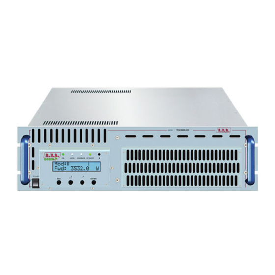
Page 11: Frontal Panel Description
TEX3500LCD 4.3 Frontal Panel Description Figure 4.1 [1] ON Green LED, lit when the transmitter is working. [2] LOCK Green led, lit when the PLL is locked on the working frequency. [3] FOLDBACK Yellow LED, lit when the foldback function is operating (automatic reduction of the delivered RF power). -
Page 12: Rear Panel Description
TEX3500LCD 4.4 Rear Panel Description Figure 4.2 [1] AIR FLOW Air flow for the forced ventilation. [2] EXT REF 10MHz Reserved for future implementations. [3] PILOT ADJ Pilot tone adjustment trimmer. [4] PHASE ADJ Phase adjustment trimmer. [5] 19 kHz PILOT OUT BNC output for the 19 kHz pilot tone. This can be used for external devices (e.g. -
Page 13: Connectors Pinouts
TEX3500LCD [31] LEFT ADJ Reserved for future implementations - adjustment trimmer for Left digital channel input. [32] RIGHT ADJ Reserved for future implementations - adjustment trimmer for Right digital channel input. [33] TOSLINK Reserved for future implementations - TOS-LINK connector for digital audio input through fiber optic. - Page 14 TEX3500LCD 4.5.4 I C Bus Type: Male DB9 TX_D RX_D Internally connected to 6 Internally connected to 4 Internally connected to 8 Internally connected to 7 4.5.5 Remote Type: Female DB15 Pin Name Type Purpose Interlock Inhibits power if closed to Ext AGC FWD Ext.
-
Page 15: Installation And Use
TEX3500LCD 5. Installation and use This section provides a step-by-step description of equipment installation and configuration procedure. Follow these procedures closely upon first power-on and each time any change is made to general configuration, such as when a new transmission station is added or the equipment is replaced. IMPORTANT: always remove the mains voltage before carrying out any type of installation and/or maintenance. -
Page 16: Installation
TEX3500LCD 5.1 Installation 5.1.1 Preliminary Requirements The equiment ventilation and the work space must be suitable for maintenance operations according to the directive in force in the country in which this device is installed. It is necessary to leave a minimum distance of 50 cm on the front and back sides of the device to have a proper functioning and to facilitate air circulation through the ventilation grids. - Page 17 TEX3500LCD TEX3500LCD @ 230 Vac Mains fuses (3x) 10A type 6x30 Table 5.1: Fuses 5.1.2 Placement of equipment Useful tips for a correct installation: • Do not use in presence of external elements near inlets and outlets ventilation systems, as they could prevent a proper ventilation of the device.
- Page 18 TEX3500LCD The transmitter normally have the outlet air in the back of machine. In this case, provide adequate ventilation of the room. COLD 50cm In alternative is cooled by forced ventilation and the air outlet is located on the roof of machine.
- Page 19 Rack power supply connections Provide for the following (applicable to operating tests and putting into service): √ Single-phase 230 (-15% / +10%) Vac mains power supply for TEX3500LCD, with adequate earth connection. √ For operating tests only: dummy load with 50 Ohm impedance and adequate capacity (minimum 3500W per TEX3500LCD).
- Page 20 TEX3500LCD N PE If transmitter require three-phase power with 3F (black, brown and grey) + N (blue) + GND (green yellow), keep in mind this requirement to connect to your distribution board. N PE Note: the mains must be equipped with adequate earth connection properly connected to the equipment.
- Page 21 Note: to ensure the safety of the operators, carry out the wiring according to the laws and regulations in force in the country where this equipment is installed. Check that the POWER switch on the front and rear of TEX3500LCD is in the “OFF” position.
- Page 22 TEX3500LCD Note: The mains must be equipped with adequate ground connection properly connected to the machine. This is a pre-requisite for ensuring operator safety and correct operation. Useful tips for a correct connection: • Provide an adequate grounding of the electrical system. This has both a direct...
- Page 23 Ensure that the POWER switch on the front panel of TEX3500LCD is set to “OFF”. Connect the mains power cable to the MAINS connector on the rear panel.
- Page 24 TEX3500LCD 5.1.5.2 Power check Ensure that the ON LED turns on. Forward power and modulation readings should appear briefly on the display. If the RF output is disabled, those readings will be zero. When the PLL locks to operating frequency, the LOCK LED will turn on. 5.1.5.3 How to enable the RF output Check output power level and set it to maximum level (unless it has already been set) from the Power Setup menu that you will have accessed by pressing the following sequence of key: ESC (opens Default Menu) ⇒...
- Page 25 TEX3500LCD 5.1.5.5 Changing the Power Good alarm threshold Change Forward Power Good alarm setting PgD from the Fnc menu as desired (factory setting is 50%). 5.1.5.6 Setting equipment I C address Change the IIC address in the MIX (Miscellaneous) menu as desired (factory setting is 01).
-
Page 26: Operation
TEX3500LCD • Preemphasis: 50 ms 75 ms • L and R (XLR type) input impedance: Switch 1: R XLR input impedance, ON = 600 W, OFF = 10 kW Switch 2: L XLR input impedance, ON = 600 W, OFF = 10 kW •... - Page 27 Menu 3 The bottom line provides instantaneous power reading (in this example 3.5kW for TEX3500LCD, falling below 1.6kW the reading back to Watt. As result of hysteresis power up , exceeding 1400W the reading back to kWatt); press button increase level, press to decrease it.
-
Page 28: Management Firmware
TEX3500LCD NOTE: If power is set to 0 W in the Power Setup Menu, the INTERLOCK OUT contact is activated and any external appliances connected to it are immediately inhibited. Next, you can review all operating parameters of the machine through the management firmware. - Page 29 TEX3500LCD Menu 0 Standby Menu Menu 2 Menu 1 Password Menu Power Adjustment Menu Menu 3 Menù di Selezione Menu 4 Operation Menu Menu 5 Power Menu Menu 6 Power Amplifier Menu Menu 7 Settings Menu Menu 8 Miscellaneous Menu...
- Page 30 TEX3500LCD State 1 As soon as operating conditions are restored, power output is re-enabled with the same settings in use prior to the alarm condition. Under 20kHz, no modulation occurs. After a preset time of about 5 minutes (not editable), a NO AUDIO condition is indicated in the main screen, but power is not inhibited.
- Page 31 Modifies Power Good threshold for forward power. The Power Good rate is a percent of equipment rated power (3500W for TEX3500LCD), not of forward output power. This means that this threshold set at 50% will give 1750 W, respectively, regardless of set power level. The Power Good feature enables output power control and reporting.
- Page 32 TEX3500LCD 5.3.3 Power Amplifier (P.A) Menu This screen is made up of four lines that can be scrolled using the buttons and shows the readings relating to final power stage: Menu 7 Note that these are readings, rather than settings, and cannot be edited (note the empty arrow). Voltage supplied by amplifier module. Current draw of amplifier module. Efficiency based on ratio of forward power to amplifier module power, in percent ( FWD PWR/(Vpa x Ipa) % ).
- Page 33 A brief description of the procedure is provided below: • Connect the PC serial port COM to the SERVICE connector on the rear panel of TEX3500LCD using a standard Male DB9 - Female DB9 serial cable. • Power on the transmitter;...
- Page 34 TEX3500LCD 5.3.5 Miscellaneous Menu (Mix) This menu lets you set equipment address in an I C bus serial connection: Menu 9 C address setting. The I C network address becomes significant when the transmitter is connected in an RVR transmission system that uses this protocol. Do not change it unless strictly required.
- Page 35 TEX3500LCD 5.3.7 Clock Menu (Rtc) This menu it lets you to set the time and date of the equipment, as well as to set temporal events to modify the power of the equipment. Menu 10 Adjustment of the hours, minutes and seconds of the equipment (HH: mm:ss) Adjustment of the date of the equipment (dd/MM/yy).
- Page 36 TEX3500LCD Tue2 Adjusting the second Tuesday event in which occurs the power variation set in percentage. Wed1 Adjusting the first Wednesday event in which occurs the power variation set in percentage. Wed2 Adjusting the second Wednesday event in which occurs the power variation set in percentage. Thu1 Adjusting the first Thursday event in which occurs the power variation set in percentage.
- Page 37 TEX3500LCD Menu 10 Note that these are readings, rather than settings, and cannot be edited (note the empty arrow). Firmware release information. Release date. Shows table loaded in the memory. USer Manual / 54 Rev. 2.0 - 27/01/20...
-
Page 38: Identification And Access To The Modules
TEX3500LCD 6. Identification and Access to the Modules 6.1 Identification of the Modules The TEX3500LCD is made up of various modules linked to each other through connectors so as to make maintenance and any required module replacement easier. 6.1.1 TEX3500LCD Upper view The figure below shows the equipment upper view with the various components pointed out. -
Page 39: Spare Parts
TEX3500LCD 6.1.2 TEX3500LCD Bottom View Figure 6.2 below shows a bottom view of the equipment and component locations.. Figure 6.2 [1] FAN1 [2] Telemetry card [3] Service voltages generation [4] FAN2 [5] Power supply interface card [6] Power supplies modules 6.2 Spare parts... -
Page 40: Working Principles
Following is a brief description of the different module functions; all diagrams and board layout diagrams are included in the “Technical Schedule” Vol.2. 7.1 Power supply The TEX3500LCD power supply can be divided into two basic sections: Services and Power Supply, which provide adequate power to the RF power amplifier modules. The unit has a rectifier (PFC) able to ensure a cos φ of 0.998 and a switching power supplies that allow an efficiency of 90%. -
Page 41: Panel Card
TEX3500LCD 7.3 Panel card The panel board accommodates the microcontroller that runs equipment firmware and all user interface elements (display, LEDs, keys, …). This board is interfaced with other equipment modules via flat cables and provides for power supply, control signals and measurement distribution. 7.4 Main Board The main board performs the following tasks: • Audio and SCA input treatment; •... -
Page 42: Power Amplifier
TEX3500LCD By entering with 5dBm it is able to deliver up to 32 W for TEX3500LCD. 7.6 Power amplifier The RF power amplification section consists in several power modules (four on the TEX3500LCD) coupled through a Wilkinson splitter and combiner using strip- line technology. Each RF module of the TEX3500LCD provides 900 W rated power using a single active element built using LD-MOS technology. -
Page 43: Bias Board
TEX3500LCD 7.8 BIAS board The main purpose of this board is to control and correct the bias voltage of the RF amplification section MOSFETs. It also provides a measure of the total current drawn by the RF modules and incorporates a dedicated circuit for power supply fault reporting. -
Page 44: Maintenance And Repair Procedures
Be sure to disconnect the amplifier’s mains supply before proceeding to any maintenance operation on the system.. 8.3 Ordinary maintenance The only regular maintenance required on the TEX3500LCD is the periodic blower replacement and dust cleaning of the air filter and of any trace of it inside the amplifier. The frequency of these operations depends on the operating conditions of the machine: like ambient temperature, dust level in the air, humidity, etc ... - Page 45 TEX3500LCD • Unscrew all the points A with the help of an Phillips screwdriver. • Unscrew laterally all the points B with the help of an Phillips screwdriver. • Unscrew all the points C with the help of an Phillips screwdriver.
-
Page 46: Module Substitutions
Only authorized and qualified technical personnel must be proceed with the replacement of the component parts in the relevant device. 8.4.1 How to replace the power supply • Open the bottom cover of TEX3500LCD by unscrewing all the screws. • Identify the power supply module to be replaced. Module 1... - Page 47 TEX3500LCD • Unscrew all the points A with the help of an Phillips screwdriver. Extract the metal plates B. • • Unscrew all the points C with the help of an slotted screwdriver. USer Manual / 54 Rev. 2.0 - 27/01/20...
- Page 48 Replace the cover and tighten all the screws necessary to close it. 8.4.2 How to replace the RF module • Open the top cover of TEX3500LCD by unscrewing all the screws. • Identify the RF module to be replaced through a visual inspection, a voltage check and/or the verification of a faulty fuse.
- Page 49 TEX3500LCD Disconnect the connectors A and unsolder the points B. • • Unscrew all the points C with the help of an Allen screwdriver. • At this point, replace the module, placing a bit of composite paste with high thermal conductivity and without silicones on the back of the new RF module.
- Page 50 • Replace the cover and tighten all the screws necessary to close it. 8.4.3 How to replace the fuses Open the top cover of TEX3500LCD by unscrewing all the screws. • • Identify the broken fuse.
- Page 51 Replace the cover and tighten all the screws necessary to close it. 8.4.4 How to replace power supply interface board • Open the bottom cover of TEX3500LCD by unscrewing all the screws. • Identify the module to be replaced. •...
- Page 52 • Open the top cover of TEX3500LCD by unscrewing all the screws. • Identify the module to be replaced. • Unscrew the seven screws A on the rear panel of the TEX3500LCD. / 54 User Manual Rev. 2.0 - 27/01/20...
- Page 53 TEX3500LCD • Unscrew all screws B on the main board cover box. • Disconnect the connector C and unscrew the RF connector D. • Remove the main board and replace it with a new spare part. • Redo all previously steps, performed in reverse, in order to reassemble and fix the module in place.
- Page 54 TEX3500LCD 8.4.5 How to replace the panel board • Unscrew the four screws A on the front panel of the TEX3500LCD. • Press the LCD panel to facilitate the extraction of the card from its seat. Disconnect the connectors B.
- Page 55 • Replace the cover and tighten all the screws necessary to close it. 8.4.7 How to replace the telemetry card • Open the bottom cover of TEX3500LCD by unscrewing all the screws. • Identify the module to be replaced. •...
- Page 56 TEX3500LCD • Remove the card and replace it with a new spare part. • Redo all previously steps, performed in reverse, in order to reassemble and fix the module in place. • Replace the cover and tighten all the screws necessary to close it. / 54 User Manual Rev. 2.0 - 27/01/20...
-
Page 57: Audigin-Tex Option
TEX3500LCD 9. Option This section displays views on the variants compared to the basic version to be requested in the order. For more information about the options, rely on the respective user manuals. 9.1 \AUDIGIN-TEX option Digital Input Left (MONO) / Right... -
Page 58: Tlw-Tex-E-3He Option
TEX3500LCD Service/RDS Type: DB9 Female 1 GND 2 RS232 TX 3 RS232 RX 4 NC 5 GND 6 NC 7 NC 8 RDS CARRIER OUT 9 PILOT IN 9.3 \TLW-TEX-E-3HE option Ethernet Type: RJ45 Female 1 TX+ 2 TX- 3 RX+... -
Page 59: Tlw-Tex3He Option
TEX3500LCD 9.4 \TLW-TEX3HE Option RS232 Bus Modem Type: DB9 Female Type: DB9 Female 1 NC 1 NC 2 TX_D 2 NC 3 RX_D 3 NC Internally connected with 5 GND 5 GND Internally connected with +12 V Internally connected with... -
Page 60: Power Up/Down Option (Only Software)
TEX3500LCD 9.5 Power UP/DOWN Option (only software) The Power UP/DOWN option modifies the signal receive function for the signals present at the telemetry connector. RF section on / off control signals are treated as control signals for RF output power level to allow for UP/DOWN setting. The UP or DOWN command is provided by switching the corresponding signal at the connector to ground for at least 500mS (pin features internal pull-up to power supply). - Page 61 ______________________________________________________________________________ ______________________________________________________________________________ ______________________________________________________________________________ ______________________________________________________________________________ ______________________________________________________________________________ ______________________________________________________________________________ ______________________________________________________________________________ ______________________________________________________________________________ ______________________________________________________________________________ ______________________________________________________________________________ ______________________________________________________________________________ ______________________________________________________________________________ ______________________________________________________________________________ ______________________________________________________________________________ ______________________________________________________________________________ ______________________________________________________________________________ ______________________________________________________________________________ ______________________________________________________________________________ ______________________________________________________________________________ ______________________________________________________________________________ ______________________________________________________________________________ ______________________________________________________________________________ ______________________________________________________________________________ ______________________________________________________________________________ ______________________________________________________________________________...
- Page 62 R.V.R Elettronica Via del Fonditore, 2 / 2c Zona Industriale Roveri · 40138 Bologna · Italy Phone: +39 051 6010506 · Fax: +39 051 6011104 e-mail: info@rvr.it ·web: http://www.rvr.it The RVR Logo, and others referenced RVR products and services are trademarks of RVR Elettronica in Italy, other countries or both. RVR ® 1998 all rights reserved. All other trademarks, trade names or logos used are property of their respective owners.