
Related Manuals for R.V.R. Elettronica TEX2503TFT


Summary of Contents for R.V.R. Elettronica TEX2503TFT
- Page 1 TEX2503 TEX2503TFT USER MANUAL VOLUME1 Manufactured by R.V.R. ELETTRONICA Italia...
- Page 2 Limitations of use can apply in respect of operating freuency, transmitter power and/or channel spacing. Declaration of Conformity Hereby, R.V.R. Elettronica, declares that this FM transmitter is in complian- ce with the essential requirements and other relevant provisions of Directive 2014/53/EU.
- Page 3 TEX2503TFT Technical Specifications TEX2503TFT Parameters U.M. Value Notes GENERALS Frequency range 87,5 - 108 Rated output power 2500 Continuously variable by software from 0 to maximum Modulation type F300E Operational Mode Mono, Stereo, MPX Working temperature °C -5 to 60...
- Page 4 TEX2503TFT AUDIO INPUTS Connector XLR F Type Balanced Left / Mono Impedance 10 k or 600 Selectable by rear panel dip switches Input Level /Adjust -12 to +12 continuosly variable Connector XLR F Type Balanced Right Impedance 10 k or 600...
-
Page 5: Table Of Contents
TEX2503TFT Table of Contents 1. Preliminary Instructions 2. Warranty 3. First aid 3.1 Treatment of electric shocks 3.2 Treatment of electrical burns 4. General description 4.1 Unpacking 4.2 Features 4.3 Description of the Front Panel 4.4 Description of the Rear Panel 4.5 Description of the Connectors... - Page 6 TEX2503TFT Quick guide 1. Turn on the switch on the front panel 2. Set the working frequency via the FRQ menu To change the value, simply use the + or - buttons and then confirm with ENTER or cancel with ESC (in mechanical key mode) or type the value directly on the display (in touchscreen mode).
-
Page 7: Preliminary Instructions
The product should not be incorporated into a rack unless retailers. it is provided with adequate ventilation or the manufacturer's if your retailer cannot help you, contact R.V.R. Elettronica instructions have been followed. and describe the issue; if the staff deems it necessary, the authorization to send the equipment will be sent to you with the appropriate instructions;... -
Page 8: First Aid
TEX2503TFT The customer always assumes the risks of loss (i.e., R.V.R. is never liable for damage or loss), until the package reaches the R.V.R. facility. For this reason, we suggest that you insure the goods for their full value. The goods must be shipped, using C.I.F. values (PAID IN ADVANCE), to the address specified by the R.V.R. -
Page 9: General Description
- Minimum rated output power: 54 dBm ±1 dB - Gain : Not applicable (the equipment is supplied without a radiant system, which is the customer’s responsibility). The TEX2503TFT is designed to be contained in a 3HE 19” rack box. 4.1 Unpacking The package contains the following: 1 TEX2503TFT... -
Page 10: Features
-3 dB (+ 5% and -50%) with respect to the nominal power of the equipment: from 1250W to 2625W for example in the case of the TEX2503TFT; beyond these limits the equipment is able to function correctly but cannot guarantee a performance of 70%. -
Page 11: Description Of The Front Panel
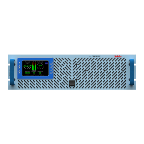
TEX2503TFT Five LEDs on the front panel provide the following status indications: ON, LOCK, FOLDBACK and RF MUTE. The exciter management firmware is based on a menu system. The user can navigate between the different submenus using the touchscreen or the four buttons: ESC, , and ENTER. On the rear panel there are the network input connectors, the audio input connectors... -
Page 12: Description Of The Rear Panel
TEX2503TFT 4.4 Description of the Rear Panel PHASE RIGHT PUSH TO EXTRACT F1=F2 Fuses 10x38 10A T 16A T R.F. TEST 25A T -60dBc 10kΩ 600Ω 10kΩ 600Ω MAINS SCA1/RDS CARRIER FREQ.ADJ SCA2 19KHz PILOT LEFT/MONO EXT AGC R.F. RFL FWD... -
Page 13: Description Of The Connectors
TEX2503TFT [23] RFL EXT. AGC Trimmer for regulation of the limitation of delivered power according to the RFL fold input. [24] FWD EXT. AGC Trimmer for regulation of the limitation of delivered power according to the FWD fold input. [25] MODEM/LAN... -
Page 14: Installation And Configuration Procedure
TEX2503TFT 5. Installation and Configuration Procedure Instructions are given in this chapter on installation and configuration of the equipment. Carefully perform all the steps described in this chapter both upon initial start-up and every time the main configuration is changed, for example when moving to a new transmission station or when replacing the equipment. -
Page 15: Installation
TEX2503TFT 5.1 Installation 5.1.1 General Requirements The ventilation of the equipment and workplace must be suitable for maintenance according to the directive in force in the country in which this equipment is installed. To ensure correct operation of the appliance, there must be a clearance of at least 50 cm at the front and back of the device to facilitate the circulation of air through the ventilation grids. - Page 16 TEX2503TFT TEX2503TFT @ 230 Vac Main fuse (2x) F 25A type 6x30 Table 5.1: Fuses 5.1.2 Placement of the device Useful tips for correct installation: • Avoid the presence of external elements near the ventilation inlets and outlets, as they could prevent proper ventilation of the device.
- Page 17 TEX2503TFT The station normally has an air outlet at the rear of the equipment: in which case, ensure adequate ventilation of the room. COLD 50cm Alternatively it is cooled by forced ventilation and the air intake is located on the roof of the equipment.
- Page 18 Note: to ensure the safety of the operators, prepare the wiring according to the laws and regulations in the country where this equipment is installed. Check that the POWER switch on the front panel of the TEX2503TFT is in the “OFF” position.
- Page 19 √ For functional tests only: • a dummy load with 50 Ohm impedance and of appropriate power (minimum 2500W for TEX2503TFT). • Coaxial cable with BNC connectors for connecting the interlock signal to the load protection. √ Connection cable kit including: •...
- Page 20 Check that the POWER switch on the front panel of the TEX2503TFT is in the “OFF” position. Connect the audio and RDS/SCA cables of your sources to the input connectors.
- Page 21 TEX2503TFT 5.1.5.2 Setting the working frequency Access the FRQ menu and use the touchscreen or keys to adjust the working frequency of the equipment. Press ENTER to confirm and wait for the LOCK LED to come on again. 5.1.5.3 Enabling the RF output If the power readings are zero, enable the RF output: •...
- Page 22 TEX2503TFT Input Sensitivity Notes SCA1/RDS - 9,2 ÷ +12 dBu Input level for 3,5 kHz overall deviation SCA2 - 9,2 ÷ +12 dBu (-30 dB) -12,5 ÷ +13,3 dBu Input level for 75 kHz overall deviation Left/Mono -12,7 ÷ +13,2 dBu...
-
Page 23: Management Firmware
TEX2503TFT 5.2 Management Firmware The device has a TFT touchscreen display, on which a set of menus are shown which indicate all the operating parameters of the product. To navigate the menus, use the touchscreen or the four mechanical keys that operate in the same way. An overall view of the menus is given in figure 5.2. - Page 24 TEX2503TFT Menu 1 NOTE: in power saving mode, the Menu key becomes ESC: press it to exit this mode. Pressing the ESC button (both in mechanical key and TouchScreen mode) while in the default menu (menu 1) opens the selection screen (menu 2), from which...
- Page 25 TEX2503TFT 5.2.2 Power Menu (PWR) This screen shows the user the parameters relating to the power delivery of the device. To edit one of the items, select it with the + or - buttons (the selected item is highlighted) and then press the ENTER button (both in mechanical key and TouchScreen mode).
- Page 26 TEX2503TFT 5.2.3 Frequency Menu (FRQ) This menu allows you to read and set the working frequency. To change the value, simply use the + or - buttons and then confirm with ENTER or cancel with ESC (in mechanical key mode) or type the value directly on the display (in touchscreen mode).
- Page 27 TEX2503TFT At any time it is possible to return to the selection screen(menu 2) by pressing the ESC button (both in mechanical key and TouchScreen mode) or after one minute of inactivity. Menu 5 Mode Selection of the audio coder mode between mono, stereo or composite mode.
- Page 28 TEX2503TFT 5.2.5 Amplifier Menu (PA) This menu allows you to read the parameters relating to the power amplifier. At any time it is possible to return to the selection screen (menu 2) by pressing the ESC button (both in mechanical key and TouchScreen mode) or after one minute of inactivity. Menu 6 Shows the forward power expressed in Watts.
- Page 29 TEX2503TFT 5.2.6 Real Time Clock (RTC) menu This menu allows you to read and set the time and date of the device. To modify the value, simply use the + or - buttons and then confirm with ENTER or cancel with ESC (in mechanical key mode) or type the value directly on the display (in touchscreen mode).
- Page 30 TEX2503TFT 5.2.7 Frequency-shift keying (FSK) menu This menu provides the FSK (Frequency Shift Keying) adjustments of the exciter. To modify the value, simply use the + or - buttons and then confirm with ENTER or cancel with ESC (in mechanical key mode) or type the value directly on the display (in touchscreen mode).
- Page 31 Adjustment of the Power Good threshold relating to the forward power. The percentage value of Power Good refers to the nominal power of the device (2500 W for the TEX2503TFT), not to the forward power delivered. So if you set a value equal to 50%, it will correspond to 1250 W, regardless of the power set.
- Page 32 TEX2503TFT 5.2.9 Version menu (Vrs) This screen shows information about the version of the device. At any time it is possible to return to the selection screen (menu 2) by pressing the ESC button (both in mechanical key and TouchScreen mode) or after one minute of inactivity.
-
Page 33: Identification And Access To The Modules
TEX2503TFT 6. Identification and Access to the Modules 6.1 Identification of the Modules The TEX2503TFT is composed of several modules which are interconnected with connectors to facilitate maintenance and replacement of the modules. 6.1.1 TEX2503TFT Top view The figure below shows the top view of the device, indicating the various components. - Page 34 TEX2503TFT 6.1.2 TEX2503TFT Bottom view The figure below shows the bottom view of the device, indicating the various components. figure 8.2 [1] Telemetry Card [2] Auxiliary Power Supply [3] Interface Card / 34 User Manual Rev. 1.0 - 04/12/20...
-
Page 35: Principles Of Operation
TEX2503TFT 7. Principles of Operation There is a schematic view of the modules and connections that make up the TEX1002 TFT in figure 7.1. R.F. R.F. 4 X R.F. 4 X R.F. R.F. OUTPUT LPF + SPLITTER DRIVER RF MODULES COMBINER DIRECT. COUPL. -
Page 36: Telemetry Board
REMOTE or INTERLOCK of the power amplifier. In case of amplifier faults, the central conductor is grounded forcing the equipment to enter stand-by mode. 7.4 Power Supply Block The TEX2503TFT power supply provides the two main power supplies: 1. Services. This voltage powers elements that do not directly affect the power supply such as the motherboard, panel board and fans. 2. Power supply. This voltage powers the RF power amplifier module and protects the equipment from any sudden fluctuations in the mains voltage. -
Page 37: Bias Board
• Low-pass filter, which also includes the power meter. In this block there is an RF pickup at approximately -46dB (for the TEX2503TFT model) with respect to the output available on a BNC connector below the transmitter output connector. This pickup is used to assess the characteristics of the carrier, but not those of the upper harmonics. -
Page 38: Maintenance And Repair Procedures
Be sure to disconnect the amplifier from the mains before proceeding with any maintenance on the system. 8.3 Ordinary maintenance The only regular maintenance required for the TEX2503TFT is periodic replacement of the fans and cleaning to remove dust in the air filter and any traces inside the amplifier. The frequency of these operations depends on the operating conditions of the device: ambient temperature, level of dust in the air, humidity, etc... -
Page 39: Options
TEX2503TFT 9. Options This section shows views on the variants with respect to the basic version to be requested when ordering. For more information about the options, refer to the respective instruction manuals. 9.1 Option /AUDIGIN-TFT Digital Input Left (MONO) / Right... -
Page 40: Option /Tlw-Tft-E-3He
TEX2503TFT Service/RDS Type: DB9 Female 1 GND 2 RS232 TX 3 RS232 RX 4 NC 5 GND 6 NC 7 NC 8 RDS CARRIER OUT 9 PILOT IN 9.3 Option /TLW-TFT-E-3HE Ethernet Type: RJ45 Female 1 TX+ 2 TX- 3 RX+... - Page 41 ______________________________________________________________________________ ______________________________________________________________________________ ______________________________________________________________________________ ______________________________________________________________________________ ______________________________________________________________________________ ______________________________________________________________________________ ______________________________________________________________________________ ______________________________________________________________________________ ______________________________________________________________________________ ______________________________________________________________________________ ______________________________________________________________________________ ______________________________________________________________________________ ______________________________________________________________________________ ______________________________________________________________________________ ______________________________________________________________________________ ______________________________________________________________________________ ______________________________________________________________________________ ______________________________________________________________________________ ______________________________________________________________________________ ______________________________________________________________________________ ______________________________________________________________________________ ______________________________________________________________________________ ______________________________________________________________________________ ______________________________________________________________________________ ______________________________________________________________________________...
- Page 42 ______________________________________________________________________________ ______________________________________________________________________________ ______________________________________________________________________________ ______________________________________________________________________________ ______________________________________________________________________________ ______________________________________________________________________________ ______________________________________________________________________________ ______________________________________________________________________________ ______________________________________________________________________________ ______________________________________________________________________________ ______________________________________________________________________________ ______________________________________________________________________________ ______________________________________________________________________________ ______________________________________________________________________________ ______________________________________________________________________________ ______________________________________________________________________________ ______________________________________________________________________________ ______________________________________________________________________________ ______________________________________________________________________________ ______________________________________________________________________________ ______________________________________________________________________________ ______________________________________________________________________________ ______________________________________________________________________________ ______________________________________________________________________________ ______________________________________________________________________________...
- Page 43 ______________________________________________________________________________ ______________________________________________________________________________ ______________________________________________________________________________ ______________________________________________________________________________ ______________________________________________________________________________ ______________________________________________________________________________ ______________________________________________________________________________ ______________________________________________________________________________ ______________________________________________________________________________ ______________________________________________________________________________ ______________________________________________________________________________ ______________________________________________________________________________ ______________________________________________________________________________ ______________________________________________________________________________ ______________________________________________________________________________ ______________________________________________________________________________ ______________________________________________________________________________ ______________________________________________________________________________ ______________________________________________________________________________ ______________________________________________________________________________ ______________________________________________________________________________ ______________________________________________________________________________ ______________________________________________________________________________ ______________________________________________________________________________ ______________________________________________________________________________...
- Page 44 R.V.R Elettronica Via del Fonditore, 2 / 2c Zona Industriale Roveri · 40138 Bologna · Italy Phone: +39 051 6010506 · Fax: +39 051 6011104 e-mail: info@rvr.it ·web: http://www.rvr.it The RVR Logo, and others referenced RVR products and services are trademarks of RVR Elettronica in Italy, other countries or both. RVR ® 1998 all rights reserved. All other trademarks, trade names or logos used are property of their respective owners.