
Related Manuals for Omega HHP-SG


Summary of Contents for Omega HHP-SG
- Page 1 User’ s Guide Shop on line at ® ® www.omega.com e-mail: info@omega.com For latest product manuals www.omegamanual.info HHP-SG HHP-SG Handheld Strain Gage Indicator Operator’s Manual...
- Page 2 Tel: (203) 359-1660 Fax: (203) 359-7700 e-mail: info@omega.com For Other Locations Visit omega.com/worldwide The information contained in this document is believed to be correct, but OMEGA accepts no liability for any errors it contains, and reserves the right to alter specifications without notice.
-
Page 3: Table Of Contents
ABLE OF ONTENTS Getting Started 1.1 Unpacking 1.2 General Description 1.3 Features Safety Considerations Installation and Operation 3.1 Front of the Meter 3.2 Rear of the Meter 3.3 Factory Settings 3.4 Battery Installation or Replacement 3.5 Transducer Hookup Calibration, Gain Selection and Adjustments 4.1 Switches &... - Page 4 IGURES AND ABLES FIGURES 3.1 Front Panel 3.2 Rear View 4.1 Zero Calibration TABLES 4.1 Gain Resistor Selection for 1.24 Volts Excitation Voltage 4.2 Gain Resistor Selection for 2.50 Volts Excitation Voltage 4.3 Zero Resistor Selection 4.4 S3 Jumper Switch Description 4.5 Solder Switch Description 5.1 Gain Switch Settings...
-
Page 5: Unpacking
ETUP Unpacking Remove the packing list and verify that you have received all equipment. If you have any questions, contact the Customer Service Department nearest you. Upon receipt of shipment, inspect the container and equipment for any signs of damage. Note any evidence of rough handling in transit. -
Page 6: Features
ETUP General Description (continued) It has two internal reference voltages for powering the bridge. The 1.24 Volt reference is used with the 1K Ohm bridge and below whereas the 2.5 Volt with the 2.5K/5K Ohm bridges and above. Failure to properly select the excitation voltage can result in the calibrator drawing excessive current. -
Page 7: Safety Considerations
AFETY ONSIDERATIONS This device is marked with the international Caution symbol. It is important to read this manual before installing or commissioning this device as it contains important information relating to Safety and EMC (Electromagnetic Compatibility). Unpacking & Inspection Unpack the instrument and inspect for obvious shipping damage. -
Page 8: Installation And Operation
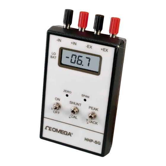
NSTALLATION AND PERATION 3.1 Front of the Meter TERMINALS BLACK RED BLACK RED LCD DISPLAY POTENTIOMETERS ZERO SPAN SWITCHES SHUNT PEAK TRACK Figure 3.1 — Front Panel... - Page 9 NSTALLATION AND PERATION DESCRIPTION ON/OFF Switch — controls power flow from the battery to all circuits. SHUNT CAL Switch — places a known resistor (59 K Ohm) across the transducer, so that a known output (half scale, 1000 count approximately) is seen, and is used to self-calibrate the instrument.
-
Page 10: Rear Of The Meter
NSTALLATION AND PERATION 3.2 Back of the Meter Figure 3.2 Rear View —... -
Page 11: Factory Settings
NSTALLATION AND PERATION 3.3 Factory Setting The calibrator is factory configured to: • 1XXX.0 decimal point location • No dummy zero • 2.5 Volt Transducer excitation • 3 mV/V sensitivity If any of the previous characteristics do not suit your application, follow steps in Section 4 of this manual to reconfigure to your needs. -
Page 12: Transducer Hookup
NSTALLATION AND PERATION 3.5 Transducer Hookup Connect the transducer to the calibrator using the binding post connectors shown in Figure 3.1. Observe proper color coding as shown on the Transducer Information Sheet provided with your transducer. Allow the transducer to warm up for a few minutes, to stabilize the drift. -
Page 13: Calibration, Gain Selection And Adjustments
& G ALIBRATION ELECTION CALIBRATION, GAIN SELECTION AND ADJUSTMENTS ZERO CALIBRATION Close appropriate switches to obtain desired gain. See Table 4.1 and 4.2 for proper selection. Gain selection is the initial step for ZERO calibration. This also provides course SPAN calibration as well. USED FOR FACTORY CALIBRATION... -
Page 14: Gain Resistor Selection For 1.24 Volts Excitation Voltage
& G ALIBRATION ELECTION Table 4.1 GAIN RESISTOR SELECTION FOR 1.24 VOLTS EXCITATION VOLTAGE SENSITIVITY S1-7 S1-6 S1-5 S1-4 S1-3 S1-2 S1-1 (mV/V) 0.45 to 0.49 0.50 to 0.54 0.55 to 0.59 0.60 to 0.65 0.66 to 0.72 0.73 to 0.79 0.80 to 0.87 0.88 to 0.96 0.97 to 1.05... -
Page 15: Gain Resistor Selection For 2.50 Volts Excitation Voltage
& G ALIBRATION ELECTION Table 4.2 GAIN RESISTOR SELECTION FOR 2.50 VOLTS EXCITATION VOLTAGE SENSITIVITY S1-7 S1-6 S1-5 S1-4 S1-3 S1-2 S1-1 (mV/V) 0.45 to 0.49 0.50 to 0.54 0.55 to 0.59 0.60 to 0.65 0.66 to 0.72 0.73 to 0.79 0.80 to 0.87 0.88 to 0.96 0.97 to 1.05... -
Page 16: Zero Resistor Selection
& G ALIBRATION ELECTION 4.1.1 Apply zero signal. 4.1.2 Using Table 4.3, select and Close the appropriate switches. (if any) Table 4.3 ZERO RESISTOR SELECTION FUNCTION ZERO OFFSET DISPLAY COUNT DISPLAY COUNT SWITCH VOLTAGE (1.24 VOLT EXC.) (2.50 VOLT EXC.) S2-1 -40 mV -757 (±3) -
Page 17: S3 Jumper Switch Description
& G ALIBRATION ELECTION SPAN CALIBRATION 4.2.1 Adjust ZERO POT to a 000 display count as suggested in section 4.1. 4.2.2 Apply full scale signal per given strain gage. For 3mV/V and 1.24 V excitation, apply 3.720 mV at ± SIGNAL input. 4.2.3 Use SPAN POT to fine tune to a 1999 display count. - Page 18 & G ALIBRATION ELECTION The sensitivities increase in 10% increments. The SPAN POT range is ±10% which should cover the entire sensitivity range from 0.5 to 4.0 mV/V. Two extra through-hole resistor locations R4, R5 and one surface mount resistor, R7 are available for covering any sensitivity value not covered by resistors in the tables above.
-
Page 19: Customized Scaling Procedure
USTOMIZED CALING ROCEDURE 5.1 CUSTOM SCALING PROCEDURE Use this procedure if you desire to scale your Strain Guage Indicator with other than the standard default scaling of 1999 counts equaling a full-scale reading. Determine the full-scale reading you desire in terms of counts. This must be between 0 and 1999 counts. - Page 20 USTOMIZED CALING ROCEDURE Look up the gain value calculated in step 5 and find the closest gain value in Table 5.1. (If the value of gain required is not contained in Table 5.1, skip to step 14) Read across the table to find the gain desired and the gain switch settings necessary to give you that value.
- Page 21 USTOMIZED CALING ROCEDURE ALTERNATE PROCEDURE FOR GAINS OUTSIDE OF TABLE 5.1 RANGE 14 Use this procedure if the gain value calculated in step 5 is not contained within Table 5.1. 15 Insert the result of step 5 into the following formula: 60,000 Rgain (ohms) = (step 5 result - 4)
-
Page 22: Gain Switch Settings
USTOMIZED CALING ROCEDURE Table 5.1 Gain Switch Settings S1-1 S1-2 S1-3 S1-4 S1-5 S1-6 S1-7 GAIN (C=CLOSE / O=OPEN) -
Page 23: Specifications
PECIFICATIONS Accuracy: ± 0.1 % Supply Voltage: 9 Vdc Transistor Battery Battery Life: 15 hours minimum with 350 ohm bridge transducer Supply Current: 20 mA Maximum (350 Ohm Bridge) Display Output: 3 1/2 Digit LCD Display with Dummy Zero, (1999 counts FS) Digit Height: 0.4”... - Page 24 PECIFICATIONS Features: • Scalable display with dummy zero • Selectable decimal point • Low voltage indication @ 5.2 Volt • Blanking overrange • Peak Detector, < 0.03% per minute bleed-off Case: Molded ABS Plastic Dimensions: 3.6" X 6.6" X 1.4" (91.4 X 167.6 X 35.6mm)
- Page 25 Where Do I Find Everything I Need for Process Measurement and Control? OMEGA…Of Course! Shop on line at www.omega.com TEMPERATURE Thermocouple, RTD & Thermistor Probes, Connectors, Panels & Assemblies Wire: Thermocouple, RTD & Thermistor Calibrators & Ice Point References Recorders, Controllers & Process Monitors...