
Related Manuals for AEG PROTECT 1 LCD


Summary of Contents for AEG PROTECT 1 LCD
- Page 1 POWER SOLUTIONS PROTECT 1 LCD Protect 1 LCD 10 kVA Protect 1 LCD 15 kVA Protect 1 LCD 20 kVA User Manual...
- Page 2 Thank you for purchasing the AEG UPS PROTECT 1 LCD from AEG Power Solutions. Safety information and operating instructions are included in this manual. To ensure correct use of the UPS, please read this manual thoroughly before operating it. Use this manual properly.
-
Page 3: Table Of Contents
CONTENT 1 Introduction ................. . . 1 1 1. - Page 4 7.4 Recycle ..................5 4 8 Troubleshooting .
- Page 5 Revision Change Date Name Created 21.07.2021...
- Page 7 SAFETY INSTRUCTIONS SAVE THESE INSTRUCTIONS. This manual contains important instructions SAVE THESE INSTRUCTIONS. This manual contains important instructions SAVE THESE INSTRUCTIONS. This SAVE THESE INSTRUCTIONS. This manual contains important instructions manual contains important instructions that should be followed during installation and maintenance of the UPS and that should be followed during installation and maintenance of the UPS and that should be followed during installation and maintenance of the UPS and that should be followed during installation and maintenance of the UPS and...
- Page 8 Safety of persons RISK OF VOLTAGE BACKFEED. The system has its own power source (the battery). Isolate the UPS and check for hazardous voltage upstream and downstream during lockout-tagout operation. Terminal blocks may be energized even if the system is disconnected from the AC power source. Dangerous voltage levels are present within the system.
- Page 9 Product safety The UPS connection instructions and operation described in the manual must be followed in the indicated order. UPS enclosure IP rating IP20. CAUTION - To reduce the risk of fire, the unit connects only to a circuit ...
- Page 10 Special precautions The unit is heavy: wear safety shoes and use vacuum lifter preferentially for handling operations. All handling operations will require at least two people (unpacking, lifting, installation in rack system). Before and after the installation, if the UPS remains de-energized for a ...
-
Page 11: Introduction
1 Introduction Thank you for selecting our UPS to protect your electrical equipment. We recommend that you take the time to read this manual to take full advantage of the many features of your UPS. Before installing your UPS, please read the booklet presenting the safety instructions. -
Page 12: Environmental Protection
1.2 Environmental protection Products are developed according to an eco-design approach. Substances Substances Substances Substances This product does not contain CFCs, HCFCs or asbestos. Packing Packing Packing Packing To improve waste treatment and facilitate recycling, separate the various packing components. The cardboard we use comprises over 50% of recycled cardboard. -
Page 13: Product Overview
2 Product Overview 2. 1 Model list The weight in this table is reference only, please see the labels on the carton for details. Net Weights Unit Size Product Description (kg) (W x H x D) (mm) 10kVA with batteries 107.4 10kVA w/o batteries 55.4... -
Page 14: Presentation
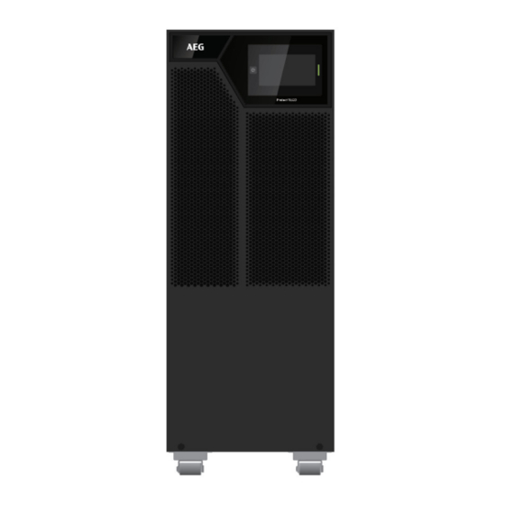
2.2 Presentation 2.2.1 2.2.1 UPS UPS model: model: 2.2.1 2.2.1 model: model: Front view Front view Front view Front view 1. Ventilation area 2. LCD Modular, including: (1)---Power button (2)---Touch screen (3)---LED indicator... - Page 15 Rear view Rear view Rear view Rear view 1. Intelligent slot 2. RS232 3. Ethernet port (RJ45, for IoT function) 4. USB 5. Disabled 6. Parallel port 7. Dry contacts (input/output) 8. RPO (Remote Power Off) contact 9. RJ45 (for EBM detect) 10.
- Page 16 E E E E BM BM (External Battery Modul (External Battery Module e e e ) ) ) ) - - - - Front Front view view (External Battery Modul (External Battery Modul Front Front view view 1. Ventilation area 2.
- Page 17 EBM (External Battery Module e e e ) ) ) ) - - - - Rear view EBM (External Battery Modul Rear view EBM (External Battery Modul EBM (External Battery Modul Rear view Rear view 1. Fuse board cover (replace EBM fuse) 2.
-
Page 18: Product Overview
3 Product Overview It is recommended to move the equipment to the installation site by using a pallet jack or a truck before unpacking. The system may be installed only by qualified electricians in accordance with applicable safety regulations. The cabinet is heavy, please install it with at least two peoples. 3.1 Unpacking and inspecting Unpacking the unit in a low-temperature environment may cause condensation occurred in and on the cabinet. -
Page 19: Checking The Accessory Kit
Packing materials must be disposed in compliance with all local regulations concerning waste. 3.2 Checking the accessory kit Verify that the following additional items are included with the unit. Standard model UPS 10K/15K/20K √ (two for every EBM Battery cable delivered) √... - Page 20 UPS model model model model 1. Place the unit on a flat surface in its final location and install ‘Tower foot’ for stability. 2. Install the unit to ground(optional): place 4pcs bolts (M8 is recommended) to the final location previously, bolt’s position please refer to below, then fix the unit to the bolts.
-
Page 21: Power Cables Connection
3.4 Power cables connection This chapter introduces how to wire AC IN/OUT cables to UPS in different modes, and UPS connecting with EBM/MBP. 3 3 3 3 ..4 4 4 4 . 1 . 1 . 1 . 1 Input /Output wiring Input /Output wiring specification specification Input /Output wiring... - Page 22 Danger! Danger! Danger! Danger! The rated current of the utility power switch must be greater than the UPS input current, otherwise the utility power switch may be burnt! Recommended circuit breaker and contactor current specifications: UPS power rating Input mode Breaker Contactor 1 phase main input...
- Page 23 Recommended output circuit breaker current specifications: UPS power rating Output mode Breaker current 1 phase output 10000VA 3 phase output 1 phase output 100A 15000VA 3 phase output 1 phase output 125A 20000VA 3 phase output Recommended battery circuit breaker current specifications: UPS power rating Breaker current 10000VA...
- Page 24 Recommended cable minimum cross-sectional area (unit: mm²) Input Output Battery Main Bypass input input Input/ power Output rating Mode 10000 15000 20000 Note: 1. Please select the larger cross-section conductor for the UPS input cable in the single source application. 2.
- Page 25 3 3 3 3 ..4 4 4 4 ..2 2 2 2 Wiring for AC Wiring for AC c c c c able (AC source to UPS) able (AC source to UPS) Wiring for AC Wiring for AC able (AC source to UPS)
- Page 26 Busbars Mode Item# Figure 5pcs 2pcs 2pcs 2pcs 2pcs 2pcs...
- Page 27 Mode 3-3(single source) Input: : : : Connect ground cable (PE) to ground screw of chassis first; Short terminal N/N with busbar #1, connect AC cable(N); Short terminal mL1/ bL1 with busbar #1, connect AC cable(L1); Short terminal mL2/ bL2 with busbar #1, connect AC cable(L2); Short terminal mL3/ bL3 with busbar #1, connect AC cable(L3).
- Page 28 Output: : : : Connect ground cable (PE) to ground screw of chassis first; Short terminal N/N with busbar #1, connect AC cable(N); Connect terminal L1/L2/L3 to AC cable(L1/L2/L3). ode 3-1(single source) Input: : : : Connect ground cable (PE) to ground screw of chassis first; Short terminal N/N with busbar #1, connect AC cable(N);...
- Page 29 Output: Connect ground cable (PE) to ground screw of chassis first; Short terminal N/N with busbar #1, connect AC cable(N); Short terminal L1/L2/L3 with busbar #3, connect AC cable(L). de 1-1(single source) Input: Connect ground cable (PE) to ground screw of chassis first; Short terminal N/N with busbar #1, connect AC cable(N);...
- Page 30 Short input terminal mL1/mL2/mL3 with busbar #7, connect main source cable(L); Short bypass terminal bL1/bL2/bL3 with busbar #5, connect bypass source cable(L). Output: Connect ground cable (PE) to ground screw of chassis first; Short terminal N/N with busbar #1, connect AC cable(N); Short terminal L1/L2/L3 with busbar #3, connect AC cable(L).
- Page 31 Connect with the configured EBM: Connect EBM to UPS with ‘Battery cable’ and ‘EBM detect cable’. Note: EBM automatic detection function supports up to 3 EBMs for Note: Note: Note: Tower 10kVA UPS. For more EBM quantity (max to 6), need configure the battery capacity in LCD.
- Page 32 Connect with user’s own EBM: Connect user’s own EBM to UPS with ‘Battery cable’ (if configured).
-
Page 33: Gland Kit Installation
3.5 Gland kit installation Before Gland kit installation, select the appropriate cables according to the wiring table in section 3.4.2 1. Open the terminal block cover 2. Assemble the glands and cables to the gland bracket according to input/output Mode & Connect the wires of cables to the terminal block/busbar according section 3.4.2. -
Page 34: Parallel System Installation And Operation (Optional)
4. Parallel System Installation and Operation (Optional) If your UPS is configured with parallel function, up to 3 UPS can be connected in parallel for power parallel or N+1 redundancy. In parallel system, the mechanical installation for each modular is same as the single system. - Page 35 Parallel system installed by 10kVA UPS (conductor cross-section, unit: mm²) Bypass Main input Output input Mode number 2 UPS 3 UPS Parallel system installed by 15kVA UPS (conductor cross-section, unit: mm²) Bypass Main input Output input Mode number 2 UPS 3 UPS Parallel system installed by 20kVA UPS (conductor cross-section, unit: mm²) Bypass...
- Page 36 Note: 1. Please select the larger cross-section conductor for the parallel system ‘ A C IN cable’ in the single source application. 2. In the three-phase output mode, if the load is an unbalanced load, the L wire of the bypass and output may exceed the rated current, and the maximum rated current will be 1.732 times.
- Page 37 3-3 configuration (dual source) 3-1 configuration (single source)
- Page 38 3-1 configuration (dual source) 1-1 configuration (single source)
- Page 39 1-1 configuration (dual source) 4 4 4 4 ..1 1 1 1 ..3 3 3 3 Wiring with external battery modular (EBM) (DC source to UPS) Wiring with external battery modular (EBM) (DC source to UPS) Wiring with external battery modular (EBM) (DC source to UPS) Wiring with external battery modular (EBM) (DC source to UPS) ...
- Page 40 Note: Common battery configuration is not suitable for standard model. Note: Note: Note:...
-
Page 41: Wiring For Parallel Signal Cable
4.2 Wiring for parallel signal cable Parallel system ‘parallel cable’ diagram: Connect each UPS one by one with ‘parallel cable’, make sure the cable is screwed to parallel port tightly. It is recommended to lock the ‘parallel cable’ (as above) for preventing the parallel ports suffering an unexpected pulling-force and causing the parallel system fault. -
Page 42: Parallel System Operation
4.3 Parallel system operation 1. Turn on the input breakers for the parallel UPS. 2. Pressing button continuously for one UPS of the system, then the system will start to turn on and enter line mode. 3. Regulate the output voltage of each UPS separately, and check if the output voltage difference is less than 0.5V among the parallel system. -
Page 43: Operation
5. Operation 5.1 LCD panel The UPS has a touch graphical LCD. It provides useful information about the UPS itself, load status, events, measurements and settings. The LED: The LED: The LED: The LED: LED status description UPS status Red on Fault mode Red flash General alarm... -
Page 44: Lcd Description
: The Buzzer The Buzzer The Buzzer The Buzzer The buzzer The buzzer The buzzer The buzzer General Meaning General Meaning General Meaning General Meaning 1 beep every 2 minutes Load supplied on bypass Load supplied on battery 1 beep every 4 seconds If battery low, beep every second 1 beep every second General warning active... - Page 45 Display Area Icon Description Bypass status and Different icon shows the phase measurements number of bypass Click on this icon will bring up a popup of measurements of the bypass Battery status Click on this icon will bring up a popup of measurements of the measurements battery...
-
Page 46: Menu Structure
5.3 Menu structure... -
Page 47: Control And Product Information
5.4 Control and product information Main menu Main menu Submenu Submenu Menu function Menu function Main menu Main menu Submenu Submenu Menu function Menu function Starts a manual battery test in stand-alone Battery test mode Battery test (Parallel) Starts a single battery test in parallel mode Control Reset fault Clear active fault... - Page 48 HE voltage high limit 5%~20% HE frequency low limit -10%~-5% HE frequency high limit 5%~10% Dual input function [Enabled], [Disabled] Disabled [Normal mode], [HE mode], UPS Mode Normal mode [CVCF mode] Output voltage [220V], [230V], [240V] 230V Auto Output frequency [Auto detection], [50Hz], [60Hz] detection Output...
-
Page 49: Starting The Ups With Utility
5.6 Starting the UPS with utility Startup preparation: Before startup the UPS, please make sure that the wiring is securely connected, otherwise there is a danger of electric shock. Verify that the total UPS output load does not exceed the rated capacity of •... -
Page 50: Starting The Ups On Battery
8. The load is powered by the UPS and the LCD shows a charging sign indicating that the battery is charging. 9. Startup the output device. If you want to cancel the Bypass enable function, please refer to chapter “User setting”. -
Page 51: Ups Shutdown
5.8 UPS shutdown Shutdown the UPS with utility power mode: UPS working with utility power, press the button for more than 3s, the LCD pops up to confirm the shutdown page. After clicking Confirm, the UPS performs shutdown. After shutdown, the UPS works in bypass mode and the output remains powered. -
Page 52: Communication
6 Communication 6.1 RS232 and USB 1. Communication cable to the serial or USB port on the computer. 2. Connect the other end of the communication cable to the RS232 or USB communication port on the UPS. 6.2 UPS remote control functions )... - Page 53 Dry out Dry out Dry out Dry out • Dry out is the relay out, dry out function can be configured. (see Settings > Dry out) Dry out Dry out Comments Comments Dry out Dry out Comments Comments Connector type 16 AWG Maximum wires Inner Relay specification 24Vdc/1A...
-
Page 54: Ups Maintenance
7 UPS Maintenance 7.1 Equipment care For the best preventive maintenance, keep the area around the equipment clean and dust free. If the atmosphere is very dusty, clean the outside of the system with a vacuum cleaner. For full battery life, keep the equipment at an ambient temperature of 25°C (77°F). - Page 55 Do not discard the UPS or the UPS batteries in the trash. This product contains sealed lead acid batteries and must be disposed as it's explained in this manual. For more information, contact your local recycling/reuse or hazardous waste center. The crossed-out wheeled bin symbol indicates that waste electrical and electronic equipment should not be discarded together with unseparated household waste but must be collected separately.
-
Page 56: Troubleshooting
8 Troubleshooting The UPS is designed for durable, automatic operation and also alert you whenever potential operating problems may occur. Usually the alarms shown by the control panel do not mean that the output power is affected. Instead, they are preventive alarms intended to alert the user. Events are silent status information that are recorded into the Event log. - Page 57 Click on “Event” “Event” “Event” icon “Event” Last 100 events If alarm exists, shows here. 4 messages for high priority alarm Problem Displayed Problem Displayed Problem Displayed Problem Displayed Possible cause Possible cause Possible cause Possible cause Remedy Remedy Remedy Remedy Phase and neutral conductor at Site wring fault...
- Page 58 Problem Displayed Problem Displayed Possible cause Possible cause Remedy Remedy Problem Displayed Problem Displayed Possible cause Possible cause Remedy Remedy Consult Service Neg Charger Failure UPS internal fault Check whether the actual Bad Battery Count Unreasonable battery number battery cell number is consistent with the set value UPS internal fault, the + DC Pos Bus Over Volt...
- Page 59 Problem Displayed Problem Displayed Problem Displayed Problem Displayed Possible cause Possible cause Possible cause Possible cause Remedy Remedy Remedy Remedy normally or fan detection cable ESS Fan lock disconnected Model Setting Wrong Wrong work mode Consult Service Neg Power Fault Negative power fault Consult Service Please confirm the connection...
-
Page 60: Troubleshooting
9 Troubleshooting 9.1 UPS block diagram 9.2 UPS specification Models Rated power 10kVA/10kW 15kVA/15kW 20kVA/20kW Rated frequency 50/60Hz Voltage range (Phase voltage) 100~300VAC Rated voltage Input 220/230/240VAC (Phase voltage) Main input Rated current (3 Phase) Main input Rated current 105A 129A (1 Phase) Bypass input... - Page 61 Models Bypass input Rated current (1 Phase) Main input frequency for 3- 40-70Hz 3 and 3-1 mode Input ≤60% rated load: 40-70Hz Main input frequency for > 6 0% rated load : 45-55Hz(50Hz system) / 54-66Hz (60Hz 1-1 mode system) Bypass Input 45-55Hz (50Hz system) / 54-66Hz (60Hz system) frequency...
- Page 62 Models Storage temperature -15°C ~ 40°C (with battery) Storage temperature -25°C ~ 60°C (without battery) Criterion Safety IEC/EN 62040-1 IEC/EN 62040-2 Performance IEC/EN 62040-3 In CVCF mode or dual source input mode, UPS needs to be de-rated to 60% capacity for 1-1 mode (rated output power and maximum charging current).
- Page 63 AEG PS – Technical data in this document does not contain any binding guarantees or warranties. Content only serves for information purposes and can be modified at any time. We will make binding commitments only upon receipt of concrete enquiries and customer notification of the relevant conditions. Due to the non-binding nature of these terms, we assume liability neither for the accuracy nor...