Advertisement
Quick Links
INSTALLATION AND
MAINTENANCE INSTRUCTIONS
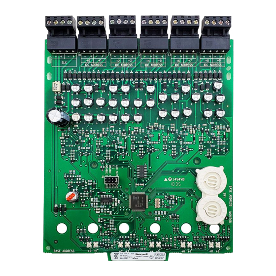
IDP-Monitor-10
Ten Input Monitor Module
SPECIFICATIONS
Normal Operating Voltage: 15-32 VDC
Stand-By Current:
3.5 mA
Alarm Current:
55 mA (assumes all ten
LEDs solid on)
Temperature Range:
32°F to 120°F (0°C to 49°C)
Humidity:
10 to 93% Non-condensing
Dimensions:
6.8˝ H x 5.8˝ W x 1.25˝ D
Accessories:
IDP-ACB Cabinet and Chassis
Wire Gauge:
12-18 AWG
Maximum SLC
Wiring Resistance:
40 Ohms
Maximum IDC
Wiring Resistance:
1500 Ohms
Maximum IDC Voltage:
10.2 VDC
Maximum IDC Current:
240 µA (each circuit)
BEFORE INSTALLING
If the modules will be installed in an existing operational
system, inform the operator and local authority that the
system will be temporarily out of service. Disconnect the
power to the control panel before installing the modules.
This system contains static sensitive components. Always
ground yourself with a proper wrist strap before handling
any circuits so that static charges are removed from the
body. The housing cabinet should be metallic and suit-
ably grounded.
NOTICE: This manual should be left with the owner/
user of this equipment.
GENERAL DESCRIPTION
The IDP-Monitor-10 Ten Input Monitor Module is in-
tended for use in an intelligent alarm system. Each moni-
tor module is intended to interface between a control
panel and normally open contact devices, such as pull
stations. A common SLC input is used for all modules,
and the initiating device loops share a common supervi-
K200-14-00
sory supply and ground. Otherwise, each monitor oper-
ates independently from the others. Each module has its
own unique address.
A pair of rotary code switches is used to set the address
of the first module from 01 to 90. The remaining modules
are automatically assigned to the next nine higher ad-
dresses. Provisions are included for disabling a maximum
of two unused modules to release the addresses to be
used elsewhere. Each module also has panel controlled
green LED indicators. The panel can cause the LEDs to
blink, latch on, or latch off.
Shipped on Board:
(1) Shunt in Class A/B position
(Shipped in Class B position, remove shunt for Class A)
Included:
(6) 1 x 4 Terminal Blocks
(4) Machine Screws
(2) Nuts
COMPATIBILITY REQUIREMENTS
To ensure proper operation, this module shall be con-
nected to a compatible Silent Knight system control panel.
COMPONENTS
The following is a description of the IDP-Monitor-10
mounting framework:
• One or two IDP-Monitor-10 modules can be
installed in a IDP-ACB cabinet.
The IDP-ACB cabinet has a built-in chassis that will ac-
commodate one or two IDP-Monitor-10 modules.
The front IDP-Monitor-10 module positions of each chassis
are offset below the rear IDP-Monitor-10 module positions
so that all of the status indicators are visible. For cabinet
dimensions refer to the IDP-ACB instruction manual.
1
firealarmresources.com
1
(2) 1
/
˝ (32mm) Stand offs
4
(3) Shunts
(10) 47k Ohm
End of Line Resistors
Figure 1: IDP-ACB Cabinet
I56-2731-003
C0202-00
C0234-03
Advertisement

Related Manuals for Honeywell SILENT KNIGHT IDP-Monitor-10


Summary of Contents for Honeywell SILENT KNIGHT IDP-Monitor-10
- Page 1 sory supply and ground. Otherwise, each monitor oper- ates independently from the others. Each module has its own unique address. A pair of rotary code switches is used to set the address of the first module from 01 to 90. The remaining modules are automatically assigned to the next nine higher ad- dresses.
- Page 2 INSTALLATION STEPS 1. Cabinet Mounting In a clean, dry area, mount the backbox using the four holes provided in the back surface of the cabinet (Figure 2). Backbox Mounting Holes C0225-00 Figure 4a: Installation of IDP-Monitor-10 module in a rear chassis position, method two C0235-00 Step 1: Insert the bottom edge of the IDP-Monitor-10 Figure 2: Typical mounting hole locations...
- Page 3 WIRING 4. A shunt is provided to disable a maximum of two un- used modules in Class B operation and one unused NOTE: All wiring must conform to applicable local module in Class A operation. Modules are disabled codes, ordinances, and regulations. from the highest address and work downward.
- Page 4 BASE ADDRESS CONNECT MODULES TO 6 7 8 9 6 7 8 9 LISTED COMPATIBLE SILENT KNIGHT CONTROL PANELS ONLY RESISTOR ELR-47K CLASS B IDC (TYPICAL) A/B SLCT COM LOSS DISABLE 1 DISABLE 2 POWER LIMITED AND SUPERVISED STATUS FROM PANEL OR INDICATORS –...