Honeywell IAQPoint2 Quick Start Manual
Gas monitor
Hide thumbs
Also See for IAQPoint2:
- Technical manual (72 pages) ,
- User manual (1637 pages) ,
- Technical manual (80 pages)
Advertisement
Available languages
Available languages
Quick Links
IAQPoint2 Gas Monitor - Quick Start Guide
Introduction
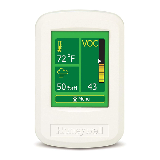
The IAQPoint2 indoor air quality monitor features a simple-to-use,
customizable touchscreen display along with triple monitoring of
indoor air quality parameters (carbon dioxide or volatile organic
compounds, plus temperature and humidity) and demand-
controlled ventilation. The IAQPoint2 monitor increases energy
efficiency in commercial buildings by triggering fan activation as a
standalone solution or via a building automation system.
Installation kits:
Tools needed:
• IAQPoint2 monitor
• drill
• backplate
• hole saw
• two plastic anchors w/metal
• drill bit
screws (wall-mount only)
• hole saw (duct-mount only)
• two metal screws (duct-mount
• #1, #2 Phillips, 1/8 inch
only)
(3 mm) screwdrivers
• Resource CD
• wire strippers
• Quick Start Guide
• 5/32 inch Allen wrench
(wall-mount only)
More detailed instructions can be found on the Resource CD.
Wall mounting
Install the monitor in an area easily accessible by a technician.
Avoid locations in which it will be subjected to vibration or
rapid temperature fluctuations. Follow local regulations and site
requirements. Position duct-mounted monitors at least 10 feet (3
meters) from any air intakes or outlets.
The monitor can be mounted onto a wall by following this
procedure. (Monitors can also be mounted to standard junction
boxes). Monitors with the optional temperature sensor must be
mounted in a location with relatively still air.
Procedure:
1.
Center the mounting plate over the wires from the wall with
the mounting holes.
2.
With a pencil, mark the locations for the two mounting holes.
Typical mounting hole distances are shown in this illustration.
2 in.
(51 mm)
1-13/16 in.
(46 mm)
3-1/4 in.
(83 mm)
2-5/16 in.
(59 mm)
1-13/16 in.
(46 mm)
Figure 1: Backplate mounting hole distances (9 holes)
English
3.
Drill a hole in the wall at each of the marks.
4.
Insert a plastic anchor into each of the holes until they are
flush with the wall.
5.
Thread the wires through the back of the backplate.
6.
Attach the backplate to the wall by screwing the supplied
metal screws into the plastic anchors. Torque installation
screws to 11 in-oz (79 Nmm).
7.
Connect each of the wires to the corresponding terminals
on the backplate, as shown in Figure 2. Wire digital models
as indicated on the label. Note that the meaning of the A
and B symbols for EIA/RS-485 wiring varies among vendors.
Terminal 6 corresponds to BACnet "+", the Modbus "D1",
and the EIA/RS-485 "B". Terminal 5 corresponds to BACnet
"-", the Modbus "D0", and EIA/RS-485 "A".
8.
Set the slide switches according to the configuration of the
monitor.
9.
Align the bottom of the bezel with the mounted assembly
and rotate the top into place. Press firmly until it snaps.
10. Torque the case hex screws to 7-10 oz-in (0.59-0.85 Nm).
wall-mount wiring label
RELAY
4-20 mA / COMM
POWER 24VAC/VDC
1
2
3
4
5
6
7
8
backplate
back of the bezel
(analog models)
RELAY
4-20 mA / COMM
POWER 24VAC/VDC
1
2
3
4
5
6
7
8
9
analog configuration switches
left: gas concentration
middle: temp or gas
right: rH
(up for 4-20 mA,
down for 2-10 v)
relay terminal block
(not present in non-
relay configurations)
back of the bezel
(digital models)
The 120 Ω network termination resistor switch
must be off (left) unless at the end of a network.
Figure 2: wiring the wall-mounted monitor
..........................................................................................................................................
Duct mounting
The monitor can be mounted on a rectangular duct at least 7 in.
× 7 in. (18 cm × 18 cm) or a round duct at least 24 inches (61 cm)
in diameter by two sheet metal screws which are supplied in the
installer's kit. Do not mount the monitor on the top or bottom of
a duct (the sampling tube is designed for horizontal installation).
Procedure:
1. Make a 1 1 / 16 -inch (27 mm) hole in the duct at the desired
sampling location.
2. Position the duct-mount bracket over the hole.
3. With a pencil, mark the locations for the two mounting holes.
4. Drill a hole in the duct at each of the marks.
5. Attach the mounting plate to the duct with the supplied sheet
metal screws. Torque the screws to 11 in-oz (79 Nmm).
6. Slide the sampling tube through the mounting bracket up to
the collar (shown in the following illustration).
7. Torque the case hex screws to screws to 7-10 oz-in (0.59-
0.85 Nm).
duct-mount wiring label
RELAY
4-20 mA / COMM
POWER 24VAC/VDC
9
10
1
2
3
4
5
6
7
8
9
10
Relay terminal
block (not
10
present on
non-relay models)
Analog slide switches
(to the right for 0-10 v,
to the left for 4-20 mA)
Figure 3: wiring the duct-mounted monitor
connector
collar
gasket
gasket
O-ring
mounting
plate clamp
mounting plate
connector orientations
cross-sections in
cross-sections in
vertical ducts
horizontal ducts
air flow
air flow
air flow
Figure 4: sampling tube and mounting plate
8.
Rotate the sampling tube until the divider shown in the cross-
section illustration above is perpendicular to the flow of air in
the duct.
9.
Lightly lubricate the connector O-ring with water to facilitate
installation.
10. Position the connector on the back of the monitor on the
sampling tube connector and twist a quarter-turn counter-
clockwise. A tight fit is normal (the O-ring on the sampling
tube provides a snug seal with the monitor). The monitor
will snap into position when it is securely attached to the
sampling tube. (The monitor can be rotated to any of four
positons.)
11. Tighten the mounting plate clamp screws.
12. Conduit is attached to the bottom of the monitor in the same
manner as standard electrical junction boxes.
First power-up
No calibration of the CO
The monitor will immediately begin operation with the default
parameters mentioned in the Menus section. If desired, the
monitor can be calibrated, however. Refer to the Technical Manual
for calibration procedures.
Warm-up
Monitors equipped with CO
On analog models, the network termination
at room temperature and 30-70% relative humidity. Typically,
resistor switch must be off (down) to prevent
crosstalk between gas and temperature
this about 1 minute and is never more than 15 minutes. They will
channels. On digital models, the switch must
be off (down) unless at the end of a network.
self-calibrate in 2 to 3 weeks. VOC sensors also require warm-up
periods of up to 15 minutes after an initial base-lining with clean
air. They will self-calibrate in 1 week.
Entering, saving, and changing passwords
intake/
exhaust
The user's password, a four-digit number, is entered by pressing
the appropriate numbers on the touchscreen. As each number
is selected, it is shown near the top of the display. After the four
numbers are displayed, press [
Press [ ß ] to delete the last digit entered (repeat to delete more
sampling tube
digits). Press [ Ñ ] to return to the Default Display screen without
entering a password.
The monitor will accept two passwords. A level-one password
(0000 by default) will allow the user to, for example, modify the
monitor's temperature setpoints. A level-two password (2967 by
default) would give the user access to additional functions such
air flow
as constraining those setpoints to a certain range, customizing
the default display, or changing passwords.
or VOC sensors is required at startup.
2
sensors require a warm-up period
2
ü
] to proceed to the main menu.
Part No. 1508-0102
Revision 3
July 2013
Advertisement

Related Manuals for Honeywell IAQPoint2


Summary of Contents for Honeywell IAQPoint2
-
Page 1: Wall Mounting
4. Drill a hole in the duct at each of the marks. flush with the wall. The IAQPoint2 indoor air quality monitor features a simple-to-use, sampling tube connector and twist a quarter-turn counter- customizable touchscreen display along with triple monitoring of clockwise. -
Page 2: Montage Mural
10. Placer le connecteur à l'arrière du moniteur sur le connecteur Le moniteur IAQPoint2 de qualité de l'air intérieur est doté d'un écran jusqu'à ce que ces pièces soient au ras du mur. du tube d'échantillonnage et tourner d'un quart de tour dans le 4.