
Related Manuals for Honeywell Fire-Lite Alarms ECC-50DA


Summary of Contents for Honeywell Fire-Lite Alarms ECC-50DA
- Page 1 Distributed Audio Amplifiers ECC-50DA/E ECC-125DA/E ECC-50BDA Installation Manual Document LS10027-000FL-E 5/21/2015 Rev: P/N LS10027-000FL-E:D ECN 15-270 firealarmresources.com...
- Page 2 Fire Alarm & Emergency Communication System Limitations While a life safety system may lower insurance rates, it is not a substitute for life and property insurance! An automatic fire alarm system—typically made up of smoke (caused by escaping gas, improper storage of flammable materi- detectors, heat detectors, manual pull stations, audible warning als, etc.).
- Page 3 LiteSpeed™, Lite-Connect™, and SWIFT™ are trademarks; and Fire-Lite® Alarms is a registered trademark of Honeywell International Inc. Microsoft® and Windows® are registered trademarks of the Microsoft Corporation. The Chrome™ browser is a trademark of Google Inc.
- Page 4 •Brief description of content you think should be improved or corrected •Your suggestion for how to correct/improve documentation Send email messages to: FireSystems.TechPubs@honeywell.com Please note this email address is for documentation feedback only. If you have any technical issues, please contact Technical Services.
-
Page 5: Table Of Contents
Table of Contents Section 1: ECC-50DA Remote Amplifier ................. 6 1.1: Installation ..............................6 1.1.1: Board Layout ............................6 1.1.2: Mounting the Cabinet ..........................7 1.1.3: Wiring Specifications ..........................8 1.1.4: Speaker Wiring ............................9 Wiring Lengths............................9 Class B (Style Y) ............................9 Class A (Style Z) ..........................10 1.1.5: Audio Riser Wiring ...........................10 1.1.6: Data BUS Wiring..........................11 1.1.7: Connecting AC Power ........................12... -
Page 6: Section 1: Ecc-50Da Remote Amplifier
Section 1: ECC-50DA Remote Amplifier 1.1 Installation This section provides information on how to install the ECC-50DA for use with the ECC-50/100 Emergency Command Center. NOTE: The term ECC-50DA is used in this manual to refer to both the ECC-50DA (120 VAC version) and the ECC-50DAE (240 VAC version) amplifier unless specified. -
Page 7: 2: Mounting The Cabinet
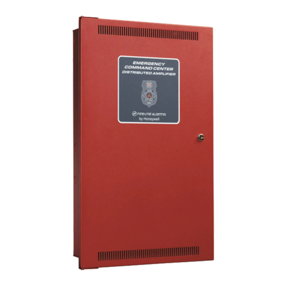
Installation ECC-50DA Remote Amplifier 1.1.2 Mounting the Cabinet Carefully unpack the system and check for shipping damage. Mount the cabinet in a clean, dry, vibration-free area where extreme temperatures are not encountered. The area should be readily accessible with sufficient room to easily install and maintain the panel. Locate the top of the cabi- net approximately five feet above the floor with the hinge mounting on the left. -
Page 8: 3: Wiring Specifications
ECC-50DA Remote Amplifier Installation 1.1.3 Wiring Specifications To avoid induced noise (transfer of electrical energy from one wire to another), keep input wiring isolated from high-current output and power wiring. Avoid pulling one multiconductor cable for the entire panel. Power-limited, nonpower-limited, and audio circuit wiring must remain separated in the cabinet. -
Page 9: 4: Speaker Wiring
Installation ECC-50DA Remote Amplifier 1.1.4 Speaker Wiring Each ECC-50DA supplies four NAC (Notification Appliance Circuit) for speaker connection. The speaker circuit can be supervised and wired Class B (Style Y) or Class A (Style Z). The speaker cir- cuit is capable of 50 watts of power at 25 Vrms or 70.7 Vrms. Wiring Lengths Number Of Speakers Total Load... -
Page 10: Class A (Style Z)
ECC-50DA Remote Amplifier Installation Class A (Style Z) Figure 1.5 illustrates how to wire speakers to the ECC-50/100 using Class A (Style Z) wiring. BATTERY + – OUT– Supervised, Power-limited Figure 1.5 Class A (Style Z) Speaker Configuration 1.1.5 Audio Riser Wiring The Audio Riser is an analog voice bus that carries the recorded voice messages from the display board to the ECC-50DAs, or the voice messages generated from a system microphone to the ECC- 50DAs. -
Page 11: 6: Data Bus Wiring
Installation ECC-50DA Remote Amplifier 1.1.6 Data BUS Wiring This section contains information on how to connect ECC-50DAs (up to 8) onto the main control Data BUS. Refer to the ECC-50/100 and/or FACP Manual for Data BUS specifications. Wire the Data BUS from TB12 on the main control board to the ECC-50DA shown in Figure 1.7 or Figure 1.8. -
Page 12: 7: Connecting Ac Power
ECC-50DA Remote Amplifier Installation 1.1.7 Connecting AC Power Transformer Standby Module Voltage Current Alarm Current ECC-50DA 25V 120 VAC, 60 Hz 115061 350 mA 1100 mA ECC-50DAE 25V 230 VAC, 50 Hz 115031 200 mA 600 mA ECC-50DA 70V 120 VAC, 60 Hz 115061 350 mA 1200 mA... -
Page 13: 8: Backup Battery
Installation ECC-50DA Remote Amplifier Connect AC power to the transformer, making sure to properly ground the unit. Then, plug the transformer output to the AC connector on the control panel. See Figure 1.10 below. . CIRCUIT 4 CIRCU – – –... -
Page 14: 9: Calculating Current Draw And Standby Battery
ECC-50DA Remote Amplifier Installation Connect the red wire from the battery harness to the positive (+) side of battery #1. BATTERY CIRCUIT 4 CIRCUIT 3 CIRCUIT 2 CIRCUIT 1 + – – – – – – – – – Note: Batteries have been rotated to show the top sides for illustration purposes only. - Page 15 Notes ECC-50/125DA Instruction Manual — P/N LS10027-000FL-E:D 5/21/2015 firealarmresources.com...
-
Page 16: Section 2: Ecc-125Da Remote Amplifier
Section 2: Amplifier ECC-125DA Remote 2.1 Installation This section provides information on how to install the ECC-125DA for use with the ECC-50/100 Emergency Command Center. NOTE: The term ECC-125DA is used in this manual to refer to both the ECC-125DA (120 VAC version) and the ECC-125DAE (240 VAC version) amplifier unless specified. -
Page 17: 2: Mounting The Cabinet
Installation ECC-125DA Remote Amplifier 2.1.2 Mounting the Cabinet Carefully unpack the system and check for shipping damage. Mount the cabinet in a clean, dry, vibration-free area where extreme temperatures are not encountered. The area should be readily accessible with sufficient room to easily install and maintain the panel. Locate the top of the cabi- net approximately five feet above the floor with the hinge mounting on the left. -
Page 18: 3: Wiring Specifications
ECC-125DA Remote Amplifier Installation 2.1.3 Wiring Specifications To avoid induced noise (transfer of electrical energy from one wire to another), keep input wiring isolated from high-current output and power wiring. Avoid pulling one multiconductor cable for the entire panel. Power-limited, nonpower-limited, and audio circuit wiring must remain separated in the cabinet. -
Page 19: 4: Speaker Wiring
Installation ECC-125DA Remote Amplifier 2.1.4 Speaker Wiring Each ECC-125DA supplies four NAC (Notification Appliance Circuit) for speaker connection. The speaker circuit can be supervised and wired Class B (Style Y) or Class A (Style Z). Speaker circuit 1 is capable of 100 watts of power at 25 Vrms. Speaker circuit 2-4 are capable of 50 watts (each) at 25 Vrms. -
Page 20: Class A (Style Z)
ECC-125DA Remote Amplifier Installation Class A (Style Z) Figure 2.5 illustrates how to wire speakers to the control panel using Class A (Style Z) wiring. CIRCUIT 4 CIRCUIT 3 CIRCUIT 2 CIRCUIT 1 BATTERY – – – – – – –... -
Page 21: 5: Audio Riser Wiring
Installation ECC-125DA Remote Amplifier 2.1.5 Audio Riser Wiring The Audio Riser is an analog voice bus that carries the recorded voice messages from the display board to the ECC-125DAs, or the voice messages generated from a system microphone to the ECC- 125DAs. -
Page 22: 6: Data Bus Wiring
ECC-125DA Remote Amplifier Installation 2.1.6 Data BUS Wiring This section contains information on how to connect ECC-125DAs (up to 8) onto the main control Data BUS. Refer to the ECC-50/100 Manual for Data BUS specifications. Wire the Data BUS from TB12 on the main control board to the ECC-125DA as shown in Figure 2.7 or Figure 2.8. -
Page 23: 7: Connecting Ac Power
Installation ECC-125DA Remote Amplifier 2.1.7 Connecting AC Power Standby Module Voltage Current Alarm Current ECC-125DA 120 VAC, 60 Hz 300 mA 2200 mA ECC-125DAE 240 VAC, 50 Hz 250 mA 1250 mA Figure 2.9 ECC-125DA AC Current Draw At installation, connect the AC terminals to the power source as shown in Figure 2.10. It may be necessary for a professional electrician to make this connection. -
Page 24: 8: Backup Battery
ECC-125DA Remote Amplifier Installation 2.1.8 Backup Battery The following steps explain how to connect the batteries (refer to Figure 2.11): Connect the black wire of the battery harness to the (-) side of the battery #2. Connect the jumper wire provided form the positive (+) side of battery #2 to the negative side of battery #1. -
Page 25: 9: Calculating Current Draw And Standby Battery
Installation ECC-125DA Remote Amplifier 2.1.9 Calculating Current Draw and Standby Battery This section helps determine the current draw and standby battery needs for your installation (18 Ampere Hours maximum will fit in cabinet). Complete the remaining instructions in Table 2.2. For batteries larger than 18 AH, use the BB-26 or BB-55FBattery Box. -
Page 26: Section 3: Ecc-50Bda Backup Remote Amplifier
Section 3: ECC-50BDA Backup Remote Amplifier 3.1 UL 464 Low Frequency Sounders This product complies with the requirements for a low frequency sounder (520Hz) as specified in UL 464 when used as part of a system with the following items. Amplifiers: Amplifier/Audio Product Description... -
Page 27: 1: Board Layout
Installation ECC-50BDA Backup Remote Amplifier 3.2.1 Board Layout Figure 3.1 shows the location of terminals, dip switch, and circuit expander connection, used in the installation of the ECC-50BDA. AC Transformer Connector Audio Riser not used + - + W G B test switches Data Bus ID... -
Page 28: 2: Mounting The Cabinet
ECC-50BDA Backup Remote Amplifier Installation 3.2.2 Mounting the Cabinet Carefully unpack the system and check for shipping damage. Mount the cabinet in a clean, dry, vibration-free area where extreme temperatures are not encountered. The area should be readily accessible with sufficient room to easily install and maintain the panel. Locate the top of the cabi- net approximately five feet above the floor with the hinge mounting on the left. -
Page 29: 3: Installing The Optional Ecc-50Wbu
Installation ECC-50BDA Backup Remote Amplifier 3.2.3 Installing the Optional ECC-50WBU The ECC-50WBU provides backup capability when the ECC-50BDA is set for the 100 watt mode with backup. The ECC-50WBU mounts onto the ECC-50BDA board with the standoffs provided. Figure 3.3 shows the location of the ECC-50WBU on the ECC-50BDA board. -
Page 30: 4: Wiring Specifications
ECC-50BDA Backup Remote Amplifier Installation 3.2.4 Wiring Specifications To avoid induced noise (transfer of electrical energy from one wire to another), keep input wiring isolated from high-current output and power wiring. Avoid pulling one multiconductor cable for the entire panel. Power-limited, nonpower-limited, and audio circuit wiring must remain separated in the cabinet. -
Page 31: 5: Speaker Wiring
Installation ECC-50BDA Backup Remote Amplifier 3.2.5 Speaker Wiring Each ECC-50BDA supplies eight NAC (Notification Appliance Circuit) for speaker connection. The speaker circuit can be supervised and wired Class B (Style Y) or Class A (Style Z). The speaker circuits are capable of 50 watts (each) at 25 Vrms or 70.7 Vrms. Wiring Lengths Number Of Speakers Total Load... -
Page 32: Class A (Style Z)
ECC-50BDA Backup Remote Amplifier Installation Class A (Style Z) Figure 3.6 illustrates how to wire speakers to the control panel using Class A (Style Z) wiring. B A + Supervised, Power-limited Figure 3.6 Class A (Style Z) Speaker Configuration Audio Riser Wiring The Audio Riser is an analog voice bus that carries the recorded voice messages from the ECC dis- play board to the ECC-50BDAs, or the voice messages generated from a system microphone to the ECC-50BDAs. -
Page 33: 6: Data Bus Wiring
Installation ECC-50BDA Backup Remote Amplifier 3.2.6 Data Bus Wiring This section contains information on how to connect up to eight (8) ECC-50BDAs onto the main control Data BUS. Refer to the ECC-50/100 Manual for Data BUS specifications. Wire the Data BUS from TB12 on the main control board to the ECC-50BDA as shown in Figure 3.8 or Figure 3.9. -
Page 34: 7: Setting The Ecc-50Bda Amplifier Mode
ECC-50BDA Backup Remote Amplifier Installation 3.2.7 Setting the ECC-50BDA Amplifier Mode Mode = Off 0 (Default) = On 1 (Setting 1) 2 (Setting 2) 3 (Setting 3) Figure 3.10 Amplifier Mode Dip Switch SW4 Settings Set the amplifier dip switch SW4 for use with the ECC-50/100. The amplifier modes are as fol- lows: •... -
Page 35: 10: Backup Battery For Ecc-50Bda
Installation ECC-50BDA Backup Remote Amplifier The AC terminals are rated as 120 VAC, 60 Hz or 240 VAC, 50 Hz. Figure 3.11 AC Connection 3.2.10 Backup Battery for ECC-50BDA The following steps explain how to connect the batteries (refer to Figure 3.12): Connect the black wire of the battery harness to the (-) side of the battery #2. -
Page 36: 11: Calculating Current Draw And Standby Battery
ECC-50BDA Backup Remote Amplifier Installation 3.2.11 Calculating Current Draw and Standby Battery This section helps determine the current draw and standby battery needs for your installation (18 Ampere Hours maximum will fit in cabinet). Complete the remaining instructions in Table 3.3. Batteries larger than 18 AH will not fit in the main control cabinet and must be housed in the BB-26 or BB-55F Battery Box. - Page 37 Manufacturer Warranties and Limitation of Liability Manufacturer Warranties. Subject to the limitations set forth herein, Manufacturer warrants that the Products manufactured by it in its Northford, Connecticut facility and sold by it to its authorized Distributors shall be free, under normal use and service, from defects in material and workmanship for a period of thirty six months (36) months from the date of manufacture (effective Jan.
- Page 38 World Headquarters 1 Firelite Place Northford, CT 06472-1653 USA 203-484-7161 fax 203-484-7118 www.firelite.com firealarmresources.com...