Bosch AMC2 Installation Manual
Enclosure with 2 din rails
Hide thumbs
Also See for AMC2:
- Installation manual (72 pages) ,
- Manual (4 pages) ,
- Installation manual (24 pages)
Table of Contents
Advertisement
Quick Links
Advertisement
Table of Contents

Related Manuals for Bosch AMC2


Summary of Contents for Bosch AMC2
- Page 1 AMC2 enclosure with 2 DIN rails AEC‑AMC2‑UL02 Installation manual...
-
Page 3: Table Of Contents
AMC2 enclosure with 2 DIN rails Table of contents | en Table of contents System overview Components of the enclosure Parts included Mounting the enclosure Connections Connecting the devices Connecting the cables Connections for supporting Universal Power Supply 12 V mode operation 3.3.1... -
Page 4: System Overview
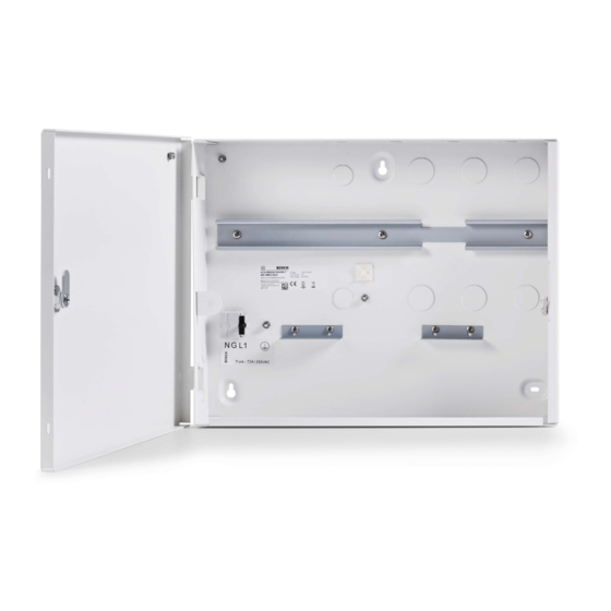
| System overview AMC2 enclosure with 2 DIN rails System overview Components of the enclosure Figure 1.1: Components of the enclosure 2022-02 | V06 | F.01U.330.017 Bosch Security Systems B.V. - Page 5 AMC2 enclosure with 2 DIN rails System overview | en Position Description Cover grounding point Main grounding point Mounting rail for power supply unit (PSU) and Access Modular Controller (AMC2) AMC2 grounding point Cable knock-outs for reader and signal cables...
-
Page 6: Parts Included
| System overview AMC2 enclosure with 2 DIN rails Parts included 2022-02 | V06 | F.01U.330.017 Bosch Security Systems B.V. - Page 7 AMC2 enclosure with 2 DIN rails System overview | en Position Description Cable ties to secure cables Three screw anchors S8 and M6 × 50 screws Bracket for cable fixing Cover grounding cable Battery cable Power supply cable (AMC2) Power supply cable (battery)
-
Page 8: Mounting The Enclosure
| Mounting the enclosure AMC2 enclosure with 2 DIN rails Mounting the enclosure The enclosure is designed to be mounted on a wall. Open the door lock of the enclosure with the provided key. Hold the enclosure at the desired position against the wall. - Page 9 AMC2 enclosure with 2 DIN rails Mounting the enclosure | en 401 mm 15,787 in 86,5 mm 200,5 mm 3,406 in 7,894 in 5 mm 0,197 in 10 mm 0,394 in 536 mm 21,102 in 5 mm 0,197 in 10 mm...
-
Page 10: Connections
| Connections AMC2 enclosure with 2 DIN rails Connections Connecting the devices Precondition: Install readers and other peripheral devices as described in the corresponding technical documentation. 1 2 3 4 5 6 Power Supply RS-485 EXT AMC2 controller /... - Page 11 Disconnect the mains supply voltage before you work on the devices inside the enclosure. Installing the components Mount the Access Modular Controller (AMC2) on the right- hand side of the mounting rail. Mount the power supply unit on the left-hand side of the mounting rail.
-
Page 12: Connecting The Cables
| Connections AMC2 enclosure with 2 DIN rails Connecting the cables Connecting the AMC2 power cable (F) Connect the 7-pin plug to the AMC2 connector labeled POWER. Connect the 4-pin plug to the power supply connector labeled OK. Connect the 2-pin plug to the power supply connector labeled DC. - Page 13 AMC2 enclosure with 2 DIN rails Connections | en Figure 3.2: Connections of the LED indicator Connecting the tamper contact (H) Connect the loose ends of the tamper contact cable to the two-pin screw connector (marked with T) at the top of the AMC2.
-
Page 14: Connections For Supporting Universal Power Supply
| Connections AMC2 enclosure with 2 DIN rails Connecting the cover grounding cable (D) Connect the mounted grounding cable (see position D of Parts included, page 6 ) to the cover grounding point (Figure 1.1, position 1) and to the grounding point on the cover of the enclosure. -
Page 15: 12 V Mode Operation
AMC2 enclosure with 2 DIN rails Connections | en 3.3.1 12 V mode operation Notice! Make sure that the power supply has the correct output voltage (12 V). Figure 3.3: 12 V mode with one battery (left); 12 V mode with two batteries (right) 12 V mode operation using one battery... - Page 16 | Connections AMC2 enclosure with 2 DIN rails 12 V mode operation using two batteries Set the switch of the power supply unit to 12 V. Connect the 2-pin plug to the power supply interface labeled BAT. Connect 1b (black) to the rechargeable negative (-) terminal of the battery.
-
Page 17: Mode Operation
AMC2 enclosure with 2 DIN rails Connections | en 3.3.2 24 V mode operation Notice! Make sure that the power supply has the correct output voltage (24 V). Figure 3.4: 24 V mode Connecting the battery cables Set the switch of the power supply unit to 24 V. - Page 18 | Connections AMC2 enclosure with 2 DIN rails Attach the connectors 2a and 2b to the bracket. Attach the bracket (C) to the back of the housing next to the batteries. 2022-02 | V06 | F.01U.330.017 Bosch Security Systems B.V.
-
Page 19: Appendices
Appendices | en Appendices UL requirements Notice! All cables connected to the AMC2 modules and the power supply are classified as Class 2 conductors. The battery cable and the AC input cable are non-power limited circuits. Notice! Maintain a minimum of 6.4 mm spacing between all class 2 or 3... -
Page 20: More Information
Visit the Bosch Building Technologies Academy website and have access to training courses, video tutorials and documents: www.boschsecurity.com/xc/en/support/training/ Visit the Bosch online product catalog for the latest technical documentation for this product. 2022-02 | V06 | F.01U.330.017 Bosch Security Systems B.V. - Page 21 AMC2 enclosure with 2 DIN rails Appendices | Bosch Security Systems B.V. 2022-02 | V06 | F.01U.330.017...
- Page 22 | Appendices AMC2 enclosure with 2 DIN rails 2022-02 | V06 | F.01U.330.017 Bosch Security Systems B.V.
- Page 24 Bosch Security Systems B.V. Torenallee 49 5617 BA Eindhoven Netherlands www.boschsecurity.com © Bosch Security Systems B.V., 2022 Building solutions for a better life. 202202221048...