Advertisement
Available languages
Available languages
Quick Links
3c
Max 3 - 5
4
3
3a
F
ENGLISH
Please read the addendum notice carefully
together with the original instructions and
retain with the original instruction manual for
future reference.
Warning!
Always check the Riving knife is locked in position
and aligned with the blade before each use and after any
maintenance.
Riving knife set-up (Fig. D, E & F)
Warning! The riving knife (3) should be delivered in the cor-
rect position for through cutting. However, before first use and
before connecting the machine to the power, make sure the
riving knife is secure, in-line with the blade and the correct dis-
tance from the blade - see fig F. Only work with the machine
if the riving knife (3) is in the upper position unless the saw
is being used for slitting operations. THE GUARD MUST BE
REMOVED FOR SLITTING OPERATIONS. IMMEDIATELY
RAISE THE RIVING KNIFE AND REATTACH THE GUARD
AFTER COMPLETING ANY OPERATION WHICH REQUIRES
REMOVAL OF THE GUARD OR LOWERING OF THE RIV-
ING KNIFE. Fitting the riving knife (3) in the upper position
is as follows:
Loosen the locking handle (3a) and pull the riving knife (3)
u
into the upper position, as shown in figure F.
Return the locking handle (3a) to the locked position.
u
(Original instructions)
3b
2b
3c
3c
3b
3b
3
2b
Warning! If the locking handle (3a) cannot be positioned in
the lower quadrant locked position (Fig. F) the riving knife
may not be correctly located.
Reposition the riving knife and reset the locking handle in the
lower quadrant position.
Warning! The Locking Handle (3A) Must Be In The Lower
Quadrant, Below Horizontal Position - See Fig F , To Be Fully
Locked. Check This Carefully.
Blade guard assembly (Fig. G)
Warning! The riving knife must be locked in the upper position
before fitting the guard.
The guard must not be fitted when the Riving knife is located
and locked in the lower position.
The blade guard (2) is supplied with a spring-loaded
u
locking pin (2c) to locate and secure the guard to the
riving knife (3). The guard must be fitted when making
through cuts to reduce the risk of injury.
Raise the saw blade and riving knife assembly by turning
u
the blade elevation handle (11) anti-clockwise as shown in
figure E.
Locate the bar in the rear of the guard (2b) downwards
u
and to the rear of the riving knife location (3b).
Press the locking pin (2c) and lower the guard to align with
u
the riving knife front location (3c).
Release the locking pin and confirm the guard is secure
u
on the riving knife.
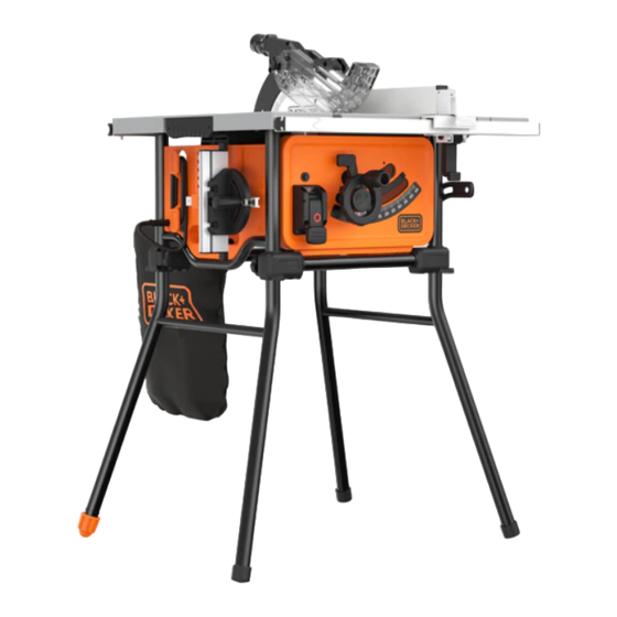
BES720
www.blackanddecker.co.eu
2c
2
2c
G
Advertisement

Related Manuals for Black & Decker BES720


Summary of Contents for Black & Decker BES720
- Page 1 BES720 www.blackanddecker.co.eu Max 3 - 5 (Original instructions) ENGLISH Please read the addendum notice carefully Warning! If the locking handle (3a) cannot be positioned in together with the original instructions and the lower quadrant locked position (Fig. F) the riving knife retain with the original instruction manual for may not be correctly located.
- Page 2 The operator should only be able to remove the guard from the riving knife by depressing the locking pin (2c) and then lifting the guard upwards. Gently tug the guard up from riving knife to ensure this is fully fitted. DEUTSCH...
- Page 3 (перевод с оригинала инструкции) PУССКИЙ Защитный кожух диска (2) снабжен подпружиненным Пожалуйста, внимательно прочтите стопорным штифтом (2c) для фиксации защитного дополнение наряду с оригинальными кожуха на расклинивающем ноже (3). Защитный кожух инструкциями и сохраните его вместе с должен быть установлен при выполнении сквозных оригинальными...
- Page 4 УКРАЇНСЬКА (переклад з оригінальної інструкції) Підніміть пильний диск і вузол розклинюючого ножа, Уважно прочитайте цей додаток разом з повернувши ручку підйому диска (11) проти годиннико- оригінальними інструкціями і збережіть вої стрілки, як показано на рисунку E. разом з оригінальними інструкціями для Встановіть...