Table of Contents
Advertisement
Quick Links
Advertisement
Table of Contents

Related Manuals for HIKVISION DS-K3B801SX Series


Summary of Contents for HIKVISION DS-K3B801SX Series
- Page 1 DS-K3B801SX Series Swing Barrier Quick Start Guide...
- Page 2 WITHOUT LIMITATION, MERCHANTABILITY, SATISFACTORY QUALITY, OR FITNESS FOR A PARTICULAR PURPOSE. THE USE OF THE PRODUCT BY YOU IS AT YOUR OWN RISK. IN NO EVENT WILL HIKVISION BE LIABLE TO YOU FOR ANY SPECIAL, CONSEQUENTIAL, INCIDENTAL, OR INDIRECT DAMAGES,...
- Page 3 During the use of device, personal data will be collected, stored and processed. To protect data, the development of Hikvision devices incorporates privacy by design principles. For example, for device with facial recognition features, biometrics data is stored in your device with encryption method;...
- Page 4 DS-K3B801SX Series Swing Barrier Quick Start Guide Regulatory Information FCC Information Please take attention that changes or modification not expressly approved by the party responsible for compliance could void the user’s authority to operate the equipment. FCC compliance: This equipment has been tested and found to comply with the limits for a Class B digital device, pursuant to part 15 of the FCC Rules.
- Page 5 DS-K3B801SX Series Swing Barrier Quick Start Guide under the EMC Directive 2014/30/EU, RE Directive 2014/53/EU,the RoHS Directive 2011/65/EU 2012/19/EU (WEEE directive): Products marked with this symbol cannot be disposed of as unsorted municipal waste in the European Union. For proper recycling, return this product to your local supplier upon the purchase of equivalent new equipment, or dispose of it at designated collection points.
- Page 6 DS-K3B801SX Series Swing Barrier Quick Start Guide Safety Instruction These instructions are intended to ensure that user can use the product correctly to avoid danger or property loss. The precaution measure is divided into Dangers and Cautions: Dangers: Neglecting any of the warnings may cause serious injury or death.
- Page 7 DS-K3B801SX Series Swing Barrier Quick Start Guide • Do not ingest battery, Chemical Burn Hazard. This product contains a coin/button cell battery. If the coin/button cell battery is swallowed, it can cause severe internal burns in just 2 hours and can lead to death.
- Page 8 DS-K3B801SX Series Swing Barrier Quick Start Guide • Please keep all wrappers after unpack them for future use. In case of any failure occurred, you need to return the device to the factory with the original wrapper. Transportation without the original wrapper may result in damage on the device and lead to additional costs.
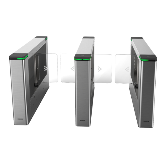
- Page 9 DS-K3B801SX Series Swing Barrier Quick Start Guide Available Models Product Name Model Description Swing Barrier DS-K3B801SX-L Left Pedestal DS-K3B801SX-M Middle Pedestal DS-K3B801SX-R Right Pedestal Scan the QR code to get User Manual of Swing Barrier. Note that mobile data charges may apply if Wi-Fi is unavailable.
-
Page 10: Table Of Contents
DS-K3B801SX Series Swing Barrier Quick Start Guide Contents Chapter 1 Overview ........................1 1.1 Introduction ........................... 1 1.2 Main Features ........................1 Chapter 2 System Wiring ......................3 Chapter 3 Installation ......................... 6 3.1 Disassemble before Installation ..................... 6 3.2 Install Pedestals ........................11 Chapter 4 Disassemble before Maintenance ................ - Page 11 DS-K3B801SX Series Swing Barrier Quick Start Guide 5.6.8 Barrier Control Wiring ....................39 5.6.9 Alarm Output Wiring ....................41 Chapter 6 Device Settings ......................42 6.1 Set Study Mode ........................42 6.2 Pair Keyfob (Optional) ......................43 6.3 Initialize Device ........................44 6.4 Switch to RS-485/RS-232 Mode ...................
-
Page 12: Chapter 1 Overview
DS-K3B801SX Series Swing Barrier Quick Start Guide Chapter 1 Overview 1.1 Introduction The swing barrier with two barriers and 24 IR lights is designed to detect unauthorized entrance or exit. By adopting the swing barrier integrated with the access control system, person should authenticate to pass through the lane via swiping IC or ID card, scanning QR code, etc. - Page 13 DS-K3B801SX Series Swing Barrier Quick Start Guide • Anti-forced-accessing The barrier will be locked automatically without open-barrier signal. • Self-detection, Self-diagnostics, and automatic alarm • Audible and visual alarm will be triggered when detecting intrusion, tailgating, reverse passing, and climbing over barrier •...
-
Page 14: Chapter 2 System Wiring
DS-K3B801SX Series Swing Barrier Quick Start Guide Chapter 2 System Wiring The preparation before installation and wiring. Steps 1. Draw a central line on the installation surface of the left or right pedestal. 2. Draw other parallel lines for installing the other pedestals. - Page 15 DS-K3B801SX Series Swing Barrier Quick Start Guide 4. Bury cables. Each lane buries 1 network cable and 1 high voltage cable. For details, see the system wiring diagram below. Figure 2-2 System Wiring Diagram (General Wiring) Note • The supplied interconnecting cable length is 5.5 m.
- Page 16 DS-K3B801SX Series Swing Barrier Quick Start Guide Figure 2-3 Wire Face Recognition Terminal Note • The supplied interconnecting cable length is 5.5 m. • The left pedestal and the middle pedestal should bury interconnecting cables for connecting the face recognition terminal.
-
Page 17: Chapter 3 Installation
DS-K3B801SX Series Swing Barrier Quick Start Guide Chapter 3 Installation 3.1 Disassemble before Installation Before installation, you should disassemble the pedestal and remove some screws. Before You Start • Keep the disassembled components and screws. • You should prepare the following tools to disassemble the pedestal: 1. Pedestal Key (supplied); 2. - Page 18 DS-K3B801SX Series Swing Barrier Quick Start Guide Figure 3-2 M5×25 Screws 3. Remove the components along the arrow direction carefully. Figure 3-3 Remove Components 4. Loosen the wing bolt (M4 × 10) at the front and back of the pedestal, and remove the front and...
- Page 19 DS-K3B801SX Series Swing Barrier Quick Start Guide Figure 3-4 Loosen Wing Bolt Figure 3-5 Remove Base Cover You can start installing the expansion screws to secure the device on the installation surface. 5. Remove the motor bottom cover. 1) Pull or push the barrier to the closed position.
- Page 20 DS-K3B801SX Series Swing Barrier Quick Start Guide Figure 3-6 M4×8 Screw 3) Pull or push the barrier to the open position, and remove the motor bottom cover.
- Page 21 DS-K3B801SX Series Swing Barrier Quick Start Guide Figure 3-7 Remove Motor Bottom Cover Note If dissembling the middle pedestal, you should dissemble two motor bottom covers. 6. Use the Allen wretch (4 mm) to loosen the 2 screws (M5 × 12) at the front or back of the pedestal base and remove the side base cover slowly.
-
Page 22: Install Pedestals
DS-K3B801SX Series Swing Barrier Quick Start Guide Note If dissembling the middle pedestal, you should dissemble two side base covers. 7. Disassemble the two protective sheets at the bottom for wiring, and you can start wiring the interconnecting cable. Figure 3-9 Disassemble Two Protective Sheets 3.2 Install Pedestals... - Page 23 DS-K3B801SX Series Swing Barrier Quick Start Guide 2. Drill holes on the ground according to the installation holes on the pedestals and insert the expansion sleeves. 3. According to the entrance and exit marks on the pedestals, move the pedestals to the corresponded positions.
- Page 24 DS-K3B801SX Series Swing Barrier Quick Start Guide 5. After installation, assemble the components and screws back to the pedestal in reverse order (except for protective sheets).
-
Page 25: Chapter 4 Disassemble Before Maintenance
DS-K3B801SX Series Swing Barrier Quick Start Guide Chapter 4 Disassemble before Maintenance Before maintaining the inner components, you should disassemble the pedestal and remove some screws. Note • Keep the disassembled components and screws organized. • You should prepare the following tools to disassemble the pedestal: 1. Pedestal Key (supplied); 2. - Page 26 DS-K3B801SX Series Swing Barrier Quick Start Guide Figure 4-1 Lock Position 2. Use the Allen wretch (4 mm) to loosen the 2 screws (M5 × 25) at the top of the device...
- Page 27 DS-K3B801SX Series Swing Barrier Quick Start Guide Figure 4-2 M5×25 Screws Position 3. Remove the components along the arrow direction carefully. Figure 4-3 Remove Components...
-
Page 28: Disassemble Motor Bottom Cover
DS-K3B801SX Series Swing Barrier Quick Start Guide 4.2 Disassemble Motor Bottom Cover After disassembling the motor bottom cover, you can maintain the lane control board and the barrier position control board. Steps 1. Pull or push the barrier to the closed position. -
Page 29: Disassemble Side Base Cover
DS-K3B801SX Series Swing Barrier Quick Start Guide Figure 4-5 Remove Bottom Cover Note If dissembling the middle pedestal, you should dissemble two motor bottom covers. 4.3 Disassemble Side Base Cover After disassembling the side base cover, you can maintain the IR sending/receiving board. - Page 30 DS-K3B801SX Series Swing Barrier Quick Start Guide Figure 4-6 Lock Position 2. Use the Allen wretch (4 mm) to loosen the 2 screws (M5 × 25) at the top of the device.
- Page 31 DS-K3B801SX Series Swing Barrier Quick Start Guide Figure 4-7 M5×25 Screws Position 3. Remove the components along the arrow direction carefully. Figure 4-8 Remove Components 4. Use the Allen wretch (4 mm) to loosen the 2 screws (M5 × 12) at the front or back of the...
-
Page 32: Disassemble Top Cover
DS-K3B801SX Series Swing Barrier Quick Start Guide Figure 4-9 Remove Side Base Cover Note If dissembling the middle pedestal, you should dissemble two side base covers. 4.4 Disassemble Top Cover After disassembling the top cover, you can maintain the components at the top of the pedestal, the IR sending/receiving board and the IR adaptor for instance. - Page 33 DS-K3B801SX Series Swing Barrier Quick Start Guide Figure 4-11 Remove Front and Back Top Cover 3. Optional: If you should install the fingerprint modules in the pedestal, you should use the key to open and remove the front and back components, and cut off the fingerprint modules' power.
- Page 34 DS-K3B801SX Series Swing Barrier Quick Start Guide Figure 4-13 Remove Top Cover...
-
Page 35: Chapter 5 General Wiring
DS-K3B801SX Series Swing Barrier Quick Start Guide Chapter 5 General Wiring 5.1 Components Introduction By default, basic components of the turnstile are connected well. The pedestals can communicate by wiring the interconnecting cables. And the turnstile supports wiring the AC electric supply for the whole system’s power supply. - Page 36 DS-K3B801SX Series Swing Barrier Quick Start Guide Figure 5-1 Components Diagram The picture displayed below describes the IR sending/receiving module and their corresponding number on the pedestal.
-
Page 37: Wiring Electric Supply
DS-K3B801SX Series Swing Barrier Quick Start Guide Figure 5-2 IR Sending/Receiving Module Position Note If the turnstile contains two lanes, standing at the entrance position, the IR modules on the left pedestal are the IR sending modules. The IR modules on the right pedestal are the IR receiving modules. -
Page 38: Wire Interconnecting Cable
DS-K3B801SX Series Swing Barrier Quick Start Guide Note • The cable bare part should be no more than 8 mm. It is suggested that you can immerse the bare part into the liquid tin. If possible, wear an insulation cap at the end of the bare cable. -
Page 39: Wire Network Switch
DS-K3B801SX Series Swing Barrier Quick Start Guide Figure 5-3 Cable Hole of Interconnecting Cable Follow the instructions below to connect the interconnecting cable. Figure 5-4 Connect Interconnecting Cable 5.4 Wire Network Switch Connect the network cable and the network switch. -
Page 40: Face Recognition Terminal Power Supply Wiring
DS-K3B801SX Series Swing Barrier Quick Start Guide Note For details, see Disassemble Side Base Cover . Figure 5-5 Network Switch Position 2. Lead out 12 V power supply from the main switch and connect it to the network switch's power interface. -
Page 41: Terminal Description
DS-K3B801SX Series Swing Barrier Quick Start Guide Figure 5-6 Face Recognition Terminal Power Supply Wiring Position 5.6 Terminal Description The lane controller contains main lane controller and sub lane controller, which controls the IR beams, motor, and other components' work. -
Page 42: Sub Control Board Terminal Description
DS-K3B801SX Series Swing Barrier Quick Start Guide Figure 5-7 Main Control Board 5.6.2 Sub Control Board Terminal Description The sub lane control board contains power supply interface, supercapacitor interface, brake interface, motor drive interface, light board interface, motor encoder interface, door open position detection interface, debug port, lane communication interface, and interconnecting interface. -
Page 43: Access Control Board Terminal Description
DS-K3B801SX Series Swing Barrier Quick Start Guide 5.6.3 Access Control Board Terminal Description Figure 5-9 Access Control Board Table 5-1 Access Control Board Terminal Description Access Control Board Terminal Description Power Output 1 +12 V Power Output Grounding Wiegand Card... - Page 44 DS-K3B801SX Series Swing Barrier Quick Start Guide Access Control Board Terminal Description Grounding RS-485 Interface Grounding RS-485 B- Connect to Card Reader RS485- RS-485 B+ Connect to Card Reader RS485+ Grounding RS-485 C- Connect to Card Reader RS485- RS-485 C+...
- Page 45 DS-K3B801SX Series Swing Barrier Quick Start Guide Access Control Board Terminal Description Alarm Output NO/NC1 Alarm Output Relay 1 (Dry Contact) COM1 NO/NC2 Alarm Output Relay 2 (Dry Contact) COM2 NO/NC3 Alarm Output Relay 3 (Dry Contact) COM3 NO/NC4 Alarm Output Relay 4 (Dry Contact)
-
Page 46: Access Control Board Serial Port Id Description
DS-K3B801SX Series Swing Barrier Quick Start Guide 5.6.4 Access Control Board Serial Port ID Description You can use the jumper cap on the access control board to switch the interface communication mode. For details about switching between RS-232 and RS-485 communication type, see Switching RS-485/RS-232 Mode. - Page 47 Use the jumper cap to switch the serial port communication mode with the lane controller. By default, the interface is wired and it is in RS-485 communication mode. If wiring other controllers (compatible with Hikvision communication protocol), use the jumper cap to switch between RS-485 and RS-232 communication mode.
-
Page 48: Rs-485 Wiring
DS-K3B801SX Series Swing Barrier Quick Start Guide 5.6.5 RS-485 Wiring Note • There are four RS-485 interfaces, which are for connecting ID card reader, IC card reader, QR code scanner, fingerprint and card reader, card recycler, text screen, fingerprint reader, and face recognition terminal. - Page 49 DS-K3B801SX Series Swing Barrier Quick Start Guide...
-
Page 50: Wiegand Wiring
DS-K3B801SX Series Swing Barrier Quick Start Guide 5.6.7 Wiegand Wiring Note Connect the OK/ERR/BZ if the access controller should control the LED and buzzer of the Wiegand card reader. 5.6.8 Barrier Control Wiring By default, the barrier has connected with the access control board. The lane control board can control the barrier status. - Page 51 DS-K3B801SX Series Swing Barrier Quick Start Guide Entering Wiring Exiting Wiring...
-
Page 52: Alarm Output Wiring
DS-K3B801SX Series Swing Barrier Quick Start Guide 5.6.9 Alarm Output Wiring Note For details about changing the relay output status via the jumper cap, see Alarm Relay Output Mode (NO/NC) . -
Page 53: Chapter 6 Device Settings
DS-K3B801SX Series Swing Barrier Quick Start Guide Chapter 6 Device Settings After installation and wiring completed, you should set the barriers closed position (study mode) before entering the working mode. You can also set the test mode, normal mode, passing mode and memory mode, pair the keyfob,... -
Page 54: Pair Keyfob (Optional)
DS-K3B801SX Series Swing Barrier Quick Start Guide 5. Set the No.1 switches of the 8-digit DIP Switch on the main control board by referring to the following figure. 6. Power on the device again. Note For details about the DIP switch value and meaning, see DIP Switch Description. -
Page 55: Initialize Device
DS-K3B801SX Series Swing Barrier Quick Start Guide Note • Only one turnstile can pair the keyfob. If multiple turnstiles are in the pairing mode, the keyfob will select only one of them to pair. • For details about DIP switch value and meaning, see DIP Switch . -
Page 56: Switch To Rs-485/Rs-232 Mode
DS-K3B801SX Series Swing Barrier Quick Start Guide 6.4 Switch to RS-485/RS-232 Mode Take the Serial Port 4 and on the access control board as an example. If the Jumper cap's position is like the picture displayed below. (The black part is the jumper cap.) The serial port is in RS-485 communication mode. -
Page 57: Switch Relay Output Mode (No/Nc)
DS-K3B801SX Series Swing Barrier Quick Start Guide 6.5 Switch Relay Output Mode (NO/NC) 6.5.1 Barrier Control Relay Output Mode The pins of the barrier control relay on the access control board is as below: Figure 6-4 Pin Appearance The jumper cap's position of barrier opening for entrance (NO) is as below:... - Page 58 DS-K3B801SX Series Swing Barrier Quick Start Guide Alarm Relay Output Mode (NC):...
-
Page 59: Chapter 7 Activation
• Get the SADP software from the supplied disk or the official website http:// www.hikvision.com/en/ , and install the SADP according to the prompts. • The device and the PC that runs the SADP tool should be within the same subnet. -
Page 60: Activate Device Via Client Software
DS-K3B801SX Series Swing Barrier Quick Start Guide Status of the device becomes Active after successful activation. 5. Modify IP address of the device. 1) Select the device. 2) Change the device IP address to the same subnet as your computer by either modifying the IP address manually or checking Enable DHCP. - Page 61 DS-K3B801SX Series Swing Barrier Quick Start Guide three kinds of following categories: upper case letters, lower case letters, numbers, and special characters) in order to increase the security of your product. And we recommend you change your password regularly, especially in the high security system, changing the password monthly or weekly can better protect your product.
-
Page 62: Appendix A. Tips For Scanning Fingerprint
DS-K3B801SX Series Swing Barrier Quick Start Guide Appendix A. Tips for Scanning Fingerprint Recommended Finger Forefinger, middle finger or the third finger. Correct Scanning The figure displayed below is the correct way to scan your finger: You should press your finger on the scanner horizontally. The center of your scanned finger should align with the scanner center. - Page 63 DS-K3B801SX Series Swing Barrier Quick Start Guide Others If your fingerprint is shallow, or it is hard to scan your fingerprint, we recommend you to use other authentication methods. If you have injuries on the scanned finger, the scanner may not recognize. You can change another...
-
Page 64: Appendix B. Dip Switch
DS-K3B801SX Series Swing Barrier Quick Start Guide Appendix B. DIP Switch B.1 DIP Switch Description The DIP switch is on the main lane control board. No.1 to No 8 is from the low bit to the high bit. When the switch is towards ON, it means the switch is enabled, otherwise, the switch is off. If you set the DIP switch like the figure displayed below, its binary value is 00001100, and its decimal value is 12. - Page 65 DS-K3B801SX Series Swing Barrier Quick Start Guide Device Mode Function Decimal Value DIP Switch Address Diagram Disable Memory Mode Keyfob Paring Disable Keyfob Mode Paring Mode Enable Keyfob Paring Mode 5 to 8 Passing Mode Controlled Bi- direction Controlled Entrance and...
- Page 66 DS-K3B801SX Series Swing Barrier Quick Start Guide Device Mode Function Decimal Value DIP Switch Address Diagram Prohibit Entrance and Controlled Exit Prohibit Entrance and Free Exit...
-
Page 67: Appendix C. Event And Alarm Type
DS-K3B801SX Series Swing Barrier Quick Start Guide Appendix C. Event and Alarm Type Event Alarm Type Tailgating Visual and Audible Reverse Passing Visual and Audible Force Accessing None Climb over Barrier Visual and Audible Overstay Visual and Audible Passing Timeout... -
Page 68: Appendix D. Table Of Audio Index Related Content
DS-K3B801SX Series Swing Barrier Quick Start Guide Appendix D. Table of Audio Index Related Content Index Content Authenticated. Card No. does not exist. Card No. and fingerprint mismatch. Climbing over the barrier. Reverse passing. Passing timeout. Intrusion. Force accessing. Tailgating. -
Page 69: Appendix E. Error Code Description
DS-K3B801SX Series Swing Barrier Quick Start Guide Appendix E. Error Code Description The swing barrier will display the error code on the seven-segment display if error occurred. Refer to the table below to find the description of each number. Error Reason... - Page 70 DS-K3B801SX Series Swing Barrier Quick Start Guide Error Reason Code Error Reason Code The Third IR Beam on Lower IR Lower IR Board 8 Offline Board Triggered The Fourth IR Beam on Lower Lower IR Board 9 Offline IR Board Triggered...
-
Page 71: Appendix F. Communication Matrix And Device Command
Device Command Scan the following QR code to get the device common serial port commands. Note that the command list contains all commonly used serial ports commands for all Hikvision access control and video intercom devices. Figure F-2 Device Command... - Page 72 UD22971B...