Advertisement
Quick Links
SV-CLCD56BA/70BA Quick Installation Guide
Safety Vision SV-CLCD56BA
Safety Vision SV-CLCD70BA
Color TFT LCD Collision Avoidance System
Quick Installation Guide
Overview
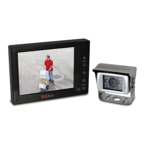
The Safety Vision SV-CLCD56BA and SV-CLCD70BA
Color TFT LCD Collision Avoidance Systems are
designed for rugged, mobile environments and turn on
automatically when the vehicle transmission is in reverse
gear. Each system includes a monitor and camera (The
SV-CLCD56BA system includes a 5.6-inch monitor, and
the SV-CLCD70BA system includes a 7.0-inch monitor.)
The system monitor has an integrated speaker, and the
system camera has an integrated microphone, permitting
the driver to both see and hear activity within the
camera's range. Although two cameras can be connected
to the SV-CLCD56BA/70BA system, only one camera is
provided with the system.
Components of the SV-CLCD56BA/70BA system include:
Safety Vision SV-LCD56BA or SV-LCD70BA Monitor,
which features:
Either a 5.6-inch or 7-0-inch TFT LCD screen
Wide field of view
Integrated speaker
Copyright © 2010 Safety Vision, LLC.
Safety Vision and the Safety Vision logo are trademarks of Safety Vision, LLC.
Notice to Users: This document is confidential and contains proprietary information belonging to Safety Vision, LLC. This document and the information
contained herein cannot be distributed, communicated, reproduced, altered, or disseminated by any means, in whole or in part, without the express
written consent of Safety Vision, LLC. Possession of this document constitutes the user's acceptance of these nondisclosure covenants. The information
in this document is believed to be accurate in all respects. However, Safety Vision cannot assume responsibility for any consequences resulting from the
use thereof. The information contained herein is subject to change without notice. Revisions or new editions to this publication may be issued to
incorporate such changes.
Safety Vision ▪ 6100 West Sam Houston Parkway North ▪ Houston, Texas 77041 ▪ USA
SV-CLCD56BA_70BA QIG Ver.1.1d.doc
Safety Vision SV-625B-KIT, which includes the
camera (Part Number SV-625B) and a 65-foot
extension cable (Part Number SV-523B) and has the
following features:
Rugged, water-resistant housing
CCD image sensor for improved image quality
Wide field of view
LEDs that generate infrared light for improved
image quality in low-light situations
Integrated microphone
Important Safety Precautions
Install and operate the SV-CLCD56BA/70BA system with
the following safety precautions in mind:
The ground (black) wire of the control box system
power cable must be connected directly to the vehicle
chassis.
Use only the correct voltage (12 to 24 VDC).
To reduce the risk of electrical shock, disconnect the
battery from the electrical system of the vehicle before
starting the installation.
Do not expose the monitor or control box to water or
other liquids.
To avoid the risk of electric shock, do not disassemble
the system components, and keep cables away from
sharp objects.
Do not block the ventilation holes in the monitor
housing.
This system is designed to assist the vehicle driver
with rear vision only. Do not attempt to view the
monitor while driving forward.
Select inconspicuous cable routes that do not interfere
with normal driver or passenger mobility.
June 2010
1
Advertisement

Related Manuals for Safety Vision SV-CLCD56BA


Summary of Contents for Safety Vision SV-CLCD56BA
- Page 1 Safety Vision, LLC. Possession of this document constitutes the user’s acceptance of these nondisclosure covenants. The information in this document is believed to be accurate in all respects. However, Safety Vision cannot assume responsibility for any consequences resulting from the use thereof.
-
Page 2: Supplied Hardware
B INTEGRATED MICROPHONE Optional Components In addition, devices other than the components supplied with the SV-CLCD56BA/70BA system (such as an additional camera) can be connected to the system. See the procedure to activating a second camera input on page 4. -
Page 3: Typical Installation
SV-CLCD56BA/70BA Quick Installation Guide June 2010 SV-625B Camera Typical Installation 1. Select an appropriate mounting location for the camera, which should be mounted on a solid, flat SV-LCD56BA/70BA Monitor surface at the highest possible point on the vehicle. 2. With the provided hardware, affix the camera 1. -
Page 4: System Power
(such as activating a (Optional) turn signal) occurs. (When this wire By default the SV-CLCD56BA/70BA monitors are set to has 12 VDC, the monitor receives receive one camera (Camera 1) input only. input from an optional Camera 2. -
Page 5: Specifications
SV-CLCD56BA/70BA Quick Installation Guide June 2010 Cleaning SV-625B Camera Turn the system off and disconnect components from Item Specification power before cleaning. Use a damp cloth for cleaning. Do Image Type Color CCD not use harsh cleaners. Horizontal Resolution 420 TV lines... -
Page 6: Warranty Information
SV. LIMITED 1-YEAR NEW PRODUCT WARRANTY Obtaining Warranty Service Safety Vision, L.P. (“SV”) makes the following limited warranty, which is effective at the time of the original end-user purchase. To obtain warranty service, the customer must contact the SV Service and Warranty Manager at 713.896.6600 or...