Table of Contents
Advertisement
Quick Links
Assembly Instructions
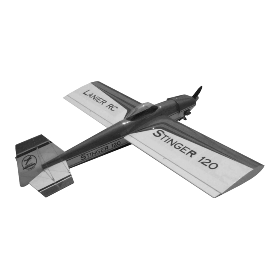
STINGER
120
ARF
Important Information:
Please inspect the plane before beginning to assemble to make sure you are happy
with it. After assembly has begun you cannot return the kit. If you find a problem
before beginning to assemble the plane you must contact us, please do not return
it to the dealer. Due to temperature changes the plane may develop some wrinkles
in the covering that you will need to remove with an iron. Be sure to seal the edges
down first so that you do not cause the covering to shrink and leave exposed areas
of wood. The model is built light to ensure good flight characteristics. With the
power available from the new breed of engines, it is necessary to use throttle man-
agement in order not to overstress the airframe. You must maintain good tight con-
trol linkage with no slop, good servos with plenty of power, and good servo arms
to protect against flutter. Sloppy linkage and overspeeding the plane will cause flut-
ter which is not covered in the warranty. Lanier R/C is proud of the care and atten-
tion that goes into the manufacture of parts for its model kits. The company war-
rants that for a period of 30 days, it will replace, at the buyers request, any parts
Lanier R/C, INC. P.O. Box 458 Oakwood, Ga. 30566 PH 770 532 6401
© copyright 1989 Lanier R/C
1
1
Advertisement
Table of Contents

Related Manuals for Lanier R/C STINGER 120 ARF


Summary of Contents for Lanier R/C STINGER 120 ARF
- Page 1 Sloppy linkage and overspeeding the plane will cause flut- ter which is not covered in the warranty. Lanier R/C is proud of the care and atten- tion that goes into the manufacture of parts for its model kits. The company war- rants that for a period of 30 days, it will replace, at the buyers request, any parts Lanier R/C, INC.
- Page 2 Bigger does fly better but some of the hardware used on small plane will not be suitable for a giant scale. Lanier R/C, INC. P.O. Box 458 Oakwood, Ga. 30566 PH 770 532 6401 © copyright 1989 Lanier R/C...
- Page 3 Assembly Instructions Lanier R/C, INC. P.O. Box 458 Oakwood, Ga. 30566 PH 770 532 6401 © copyright 1989 Lanier R/C...
-
Page 4: Wing Assembly
Set aside to dry and install the other aileron. Clamp wing hold down tabs together while epoxy sets. Locate the dihedral brace. Trial fit the brace into the slot. Lanier R/C, INC. P.O. Box 458 Oakwood, Ga. 30566 PH 770 532 6401 © copyright 1989 Lanier R/C... - Page 5 When satisified with the fit, apply a coat of epoxy to the reinforcement plate and bolt in place on the wing with the wing Lanier R/C, INC. P.O. Box 458 Oakwood, Ga. 30566 PH 770 532 6401 © copyright 1989 Lanier R/C...
-
Page 6: Tail Assembly
Cut carefully and cut only the covering, of the fuselage. don’t cut the balsa underneath as this would weaken the stab and fin. Lanier R/C, INC. P.O. Box 458 Oakwood, Ga. 30566 PH 770 532 6401 © copyright 1989 Lanier R/C... - Page 7 Work the surfaces back and forth several time to make sure there are no binds and check gap to make sure it is tight. Lanier R/C, INC. P.O. Box 458 Oakwood, Ga. 30566 PH 770 532 6401 © copyright 1989 Lanier R/C...
- Page 8 Using two #6x3/4” sheet metal screws, screw the tail wheel bracket in place with the flying wire bracket underneath the front screw. Lanier R/C, INC. P.O. Box 458 Oakwood, Ga. 30566 PH 770 532 6401 © copyright 1989 Lanier R/C...
- Page 9 5” behind the front of the fuselage. Press down the covering to find the holes and remove the covering with a knife. Lanier R/C, INC. P.O. Box 458 Oakwood, Ga. 30566 PH 770 532 6401 © copyright 1989 Lanier R/C...
- Page 10 Do this on both sides. Attach the tail wheel with the 1/8” wheel collar supplied. Lanier R/C, INC. P.O. Box 458 Oakwood, Ga. 30566 PH 770 532 6401 © copyright 1989 Lanier R/C...
-
Page 11: Cowl Mounting
8 hours. Any smudges can be cleaned with water while the glue is still wet. Cowl blocks Lanier R/C, INC. P.O. Box 458 Oakwood, Ga. 30566 PH 770 532 6401 © copyright 1989 Lanier R/C... - Page 12 After the epoxy has cured, round the cor- ners of the blocks so there are no sharp edges to cut the cowl. Lanier R/C, INC. P.O. Box 458 Oakwood, Ga. 30566 PH 770 532 6401 © copyright 1989 Lanier R/C...
- Page 13 You may want to wait till the engine is Lanier R/C, INC. P.O. Box 458 Oakwood, Ga. 30566 PH 770 532 6401 © copyright 1989 Lanier R/C...
-
Page 14: Radio Installation
4-40 nut on each end. Screw a 4- 40 golden clevis on each end and connect one end to aileron horn and the other to the servo arm. Lanier R/C, INC. P.O. Box 458 Oakwood, Ga. 30566 PH 770 532... - Page 15 You will then mount the Lanier R/C, INC. P.O. Box 458 Oakwood, Ga. 30566 PH 770 532 6401 © copyright 1989 Lanier R/C...
- Page 16 E-Z con- nector. This set up shows a Fox 2.4, if you are using a different engine you will have to adjust accordingly. Lanier R/C, INC. P.O. Box 458 Oakwood, Ga. 30566 PH 770 532 6401 © copyright 1989 Lanier R/C...
- Page 17 CG. This is fine with a gas motor because they have a fuel pump. A glow motor will require that the tank be mount- ed forward. Lanier R/C, INC. P.O. Box 458 Oakwood, Ga. 30566 PH 770 532 6401 © copyright 1989 Lanier R/C...
-
Page 18: Control Throws
All you can get Aileron All you can get Rudder All you can get Center of Gravity 4-1/2” to 5” behind leading edge Lanier R/C, INC. P.O. Box 458 Oakwood, Ga. 30566 PH 770 532 6401 © copyright 1989 Lanier R/C... -
Page 19: Airframe Components
4. Nylon swing in keepers 6mm x 13mm 5. Aluminum bracket 2. Shaped cowl blocks 6. Flying wire brackets 7. 4-40 x3/4” socket head screws Lanier R/C, INC. P.O. Box 458 Oakwood, Ga. 30566 PH 770 532 6401 © copyright 1989 Lanier R/C... -
Page 20: Equipment Required
11. Pliers (needle nose) 12. Mixing sticks 13. 36” yard stick or tape measure 14. Scissors 15. Moto tool with sanding drum. Lanier R/C, INC. P.O. Box 458 Oakwood, Ga. 30566 PH 770 532 6401 © copyright 1989 Lanier R/C...