
Related Manuals for Bosch CL400


Summary of Contents for Bosch CL400
- Page 1 Antriebs- und Steuerungstechnik CL400 / CL500 COM-E Module Description Edition...
- Page 2 Module Description 1070 072 196-101 (00.06) GB E 2000 by Robert Bosch GmbH, Erbach / Germany All rights reserved, including applications for protective rights. Reproduction or distribution by any means subject to our prior written permission. Discretionary charge 10.00 DM...
-
Page 3: Table Of Contents
Contents Contents Page Safety Instructions ......1- -1 Intended Use ......... . . 1--1 Qualified Personnel . - Page 4 Contents General Information Regarding BUEP-E and BUEP19E ....... . 7- -1 Parameter BUEP-E / BUEP19E .
-
Page 5: Safety Instructions
Safety Instructions 1- -1 Safety Instructions Before you start working with COM-E, we recommend that you thoroughly familiarize yourself with the contents of this manual. Keep this manual in a place where it is always accessible to all users. Intended Use This instruction manual presents a comprehensive set of instructions and in- formation required for the standard operation of the described products. -
Page 6: Qualified Personnel
1- -2 Safety Instructions Qualified Personnel This instruction manual is designed for specially trained personnel. The rele- vant requirements are based on the job specifications as outlined by the ZVEI and VDMA professional associations in Germany. Please refer to the following German-Language publication: Weiterbildung in der Automatisierungstechnik Publishers: ZVEI and VDMA Maschinenbau Verlag... -
Page 7: Safety Markings On Components
Safety Instructions 1- -3 Safety Markings on Components DANGER! High voltage! DANGER! Corrosive battery acid! CAUTION! Electrostatically sensitive components! Disconnect mains power before opening! Lug for connecting PE conductor only! Functional earthing or low-noise earth only! Screened conductor only! 1070 072 196-101 (00.06) GB... -
Page 8: Safety Instructions In This Manual
1- -4 Safety Instructions Safety Instructions in this Manual DANGEROUS ELECTRICAL VOLTAGE This symbol warns of the presence of a dangerous electrical voltage. In- sufficient of lacking compliance with this warning can result in personal injury. DANGER This symbol is used wherever insufficient or lacking observance of this in- struction can result in personal injury. -
Page 9: Safety Instructions For The Described Product
The consequences may be severe personal injury or damage to equipment or the environment. Therefore, any system retrofitting or modification utilizing equipment components from other manufac- turers will require express approval by Bosch. DANGEROUS ELECTRICAL VOLTAGE Unless described otherwise, maintenance procedures must always be carried out only while the system is isolated from the power sup- ply. - Page 10 1- -6 Safety Instructions CAUTION Danger to the module! All ESD protection measures must be observed when using the mod- ule! Prevent electrostatic discharges! Observe the following protective measures for electrostatically endangered modules (EEM)! D The Employees responsible for storage, transport and handling must be trained in ESD protection.
-
Page 11: Documentation, Software Release And Trademarks
See also chapter 2.5.4. Trademarks All trademarks referring to software that is installed on Bosch products when shipped from the factory represent the property of their respective owners. At the time of shipment from the factory, all installed software is protected by copyright. - Page 12 1- -8 Safety Instructions 1070 072 196-101 (00.06) GB...
-
Page 13: Hardware
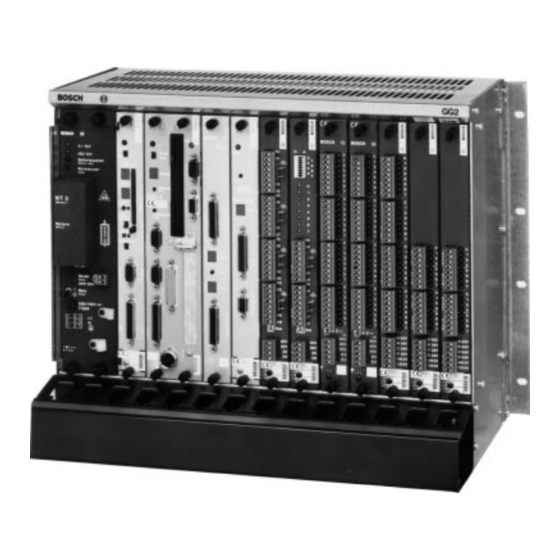
2- -1 Hardware The COM-E module is provided with a serial V.24/20 mA interface and an Ethernet interface (10Base-T) which make it possible to couple the CL400 / CL500 controllers with other Bosch controllers or other communication-ca- pable devices. Power Supply The COM-E does not require an external power supply. -
Page 14: Front Panel
2- -2 Hardware Front Panel Status display Channel 0 25-pin socket V.24/20 mA Channel 0 Reset button Link-LED Link Status display Channel 1 Receive-LED Receive Transmit-LED Transmit 10Base-T Ethernet socket Channel 1 Version identification Labeling field Status Display Each of the two channels on the COM-E is provided with a status display. D For channel 0, the upper 7-segment display is responsible. - Page 15 Hardware 2- -3 Reset Button Pressing the reset button starts reinitialization of COM-E’s operating soft- ware. D All active jobs are aborted undefined. D All jobs are deleted from the job queue. D STOP and CLAB requests of the module are deleted. Link-LED This LED indicates that the link integrity signals can be exchanged between COM-E and the coupled partner device.
-
Page 16: Slot
A maximum of 5 COM-Es can be operated in a PLC. In server operation, even more modules can be implemented. CL400 For the CL400, the slots 4 to 14 in the GG2 are at your free disposal. In GG2/K, the slots 4 to 8 are freely available. CL500 For the CL500, the slots 5 to 14 in the GG2 are at your free disposal. -
Page 17: V.24/20 Ma Interface
Hardware 2- -5 V.24/20 mA Interface The V.24/20 mA interface is available at channel 0. Via this interface, devices that are equipped with a V.24/20 mA interface themselves can be connec- ted. The following protocols can be used: D BUEP03E Transmission protocol for free configuration D BUEP19E Protocol for secure data transmission... -
Page 18: Ethernet Interface
2- -6 Hardware Ethernet Interface The Ethernet is connected via a twisted pair cable with RJ45 connector. The in IEEE 802.3 defined terminal conditions for 10Base-T are applicable: D Network topology star D Max. transmission rate: 10 Mbit/s D Max. segment length: 100 m D 100 Ω... -
Page 19: Settings On The Com-E
Hardware 2- -7 Settings on the COM-E The settings must be made prior to the COM-E’s commissioning. CAUTION Danger to the module! All ESD protection measures must be observed when using the mod- ule! Prevent electrostatic discharges! DIP Switch Explanation Setting the block address Protocol-specific setting channel 0 Reserved... -
Page 20: Block Address Of Com-E
At the CL400 / CL500’s system bus, the COM-E occupies a block of 256 kB or four blocks. The block address of the COM-E is set at DIP switch S2. The settings are made in the same way as for all other modules of the CL400 / CL500 controller series. System Bus Address [hex]... -
Page 21: Protocol-Specific Settings
Hardware 2- -9 2.5.2 Protocol-Specific Settings Protocol-specific settings for channel 0 are to be located at DIP switch S3 and S6. At DIP switch S6, only the switches 1 and 2 are assigned to channel The DIP switches S4, S5, and S6 with switch 3 and 8 are reserved for future extensions, and must always be switched to OFF. - Page 22 2- -10 Hardware Function Channel reserved BUEP19E: Priority centr. jobs BUEP64: Priority centr. jobs BUEP03E: Data length 8 bit BUEP19E: Priority decentr. jobs BUEP64: Priority decentr. jobs BUEP03E: Data length 7 bit BUEP64:Protocol end with DLE ETX BUEP64:Protocol end with DLE ETB BUEP03E: 10400 baud at S3 = 600 baud...
- Page 23 Hardware 2- -11 20 mA Interface Signal level and assignment of the connectors comply with the guidelines: ”VDI Richtlinien 2880, Blatt 2” for programmable logic controllers, process and data interfaces (limitation: max. reverse voltage 27 V). The 20 mA inter- faces can be, in dependence on the pin assignment, switched to active, i.e.
- Page 24 Hardware Length of Line The maximum applicable length of the line is dependent on the baud rate. For the Bosch cable 14 x 0.14 twisted, shielded, order no. 1070 910 152, the following lengths apply: Transmission Speed [baud] V.24 [m]...
-
Page 25: Ethernet-Specific Settings
Hardware 2- -13 2.5.4 Ethernet-Specific Settings Ethernet Address Each module has an impressed Ethernet address. This address is unique worldwide, and should not be altered. The Ethernet address consists of 6 address bytes and is constructed as fol- lows: Fixed Part [hex] Module-Specific Modification of the Ethernet address is possible via the configuration file. -
Page 26: Configuration File
2- -14 Hardware Configuration File With the configuration file, several presettings and default values on the COM-E can be changed. The file is imported into the COM-E module using the WinSPS editor, version 2.3 and higher, submenu ’Controls’, via SK, ZS or COM-E, where it is then filed in a non-volatile way. - Page 27 Hardware 2- -15 Retransmissiontimer Default: 200 ms This time value determines the repeat time of a message. If, e.g., a request message is not answered with a response message, the request message is repeated after the retransmission time has elapsed. Example for an entry in the configuration file: Retransmissiontimer: 400 ;...
- Page 28 2- -16 Hardware IP-Table Normally, the IP table is not necessary. In an IP table, the references be- tween the IP address, the module name and the Ethernet address can be established; compare to routing table. By specifying this table the message load can be reduced, the module name on COM-E can be determined, and the Ethernet address for this module can be defined anew.
- Page 29 Hardware 2- -17 Ethernet-Overwrite Default: 0 ; no overwrite The Ethernet overwrite function causes the acceptance of the IP table’s Ethernet address in the module if the IP address given in the system table is identical with the address in the table. Example: D In the system table, the COM-E is listed with the IP address 142.2.40.123.
- Page 30 2- -18 Hardware Password Default: no password A writing access to a controller with a COM-E module can be protected with a password. The password is only checked for communication with the PG (programming unit) or other external connections. During a COM-E -- COM-E communication, the password is not active.
-
Page 31: Example Of A Configuration File
Hardware 2- -19 2.6.2 Example of a Configuration File ; Configuration file COM-E Project XY of 6-12-98. ; ----------------------------------------------- ; Comments are marked with a ’;’ ; Spaces and tabulators serve as delimiters. ; Communication parameters ; ------------------------ Retransmissiontimer: ; Time in milliseconds (default: 200 ms) Retransmissioncounter: ;... -
Page 32: Status Display
2- -20 Hardware Status Display Each channel of the COM-E module is provided with a status display. It shows all channel-related statuses and error messages. These messages are assigned directly to the corresponding channel, and thus to this protocol. Lower Upper Explanation Display... -
Page 33: Technical Data
Hardware 2- -21 Technical Data Technical Data COM-E Interfaces D V.24/20 mA as per guideline ”VDI 2880 Blatt 2” D 20mA interface is electrically iso- lated Baudrates V.24/20 mA interface 600 to 57600 bd Current uptake internally D 5V voltage supply 500 mA typical D +12V ISO voltage supply 70 mA + 20 mA per active current loop... - Page 34 2- -22 Hardware Notes: 1070 072 196-101 (00.06) GB...
-
Page 35: Plc Interface
D R5CON The PLC interface enables the user to allocate a job to the COM-E; this is also called ’client characteristics of the CL400 / CL500’. The function modules do not offer a job monitoring function (time-out). Job monitoring is provided by the firmware of COM-E. - Page 36 3- -2 PLC Interface Notes: 1070 072 196-101 (00.06) GB...
-
Page 37: R5Init
R5INIT 4- -1 R5INIT Characteristics Characteristics R5INIT Module name R5INIT Number of parameters Reserved markers M230 to M254 Communication Modules The initialization R5INIT function module creates different tables in the ZS Central Unit and on the COM-E module, and fills them out with information which is accessed during communication between these modules. - Page 38 4- -2 R5INIT 4.2.1 Input Parameters Parameter Attribute Description Module number of computer interface 0 Module number of computer interface 1 Module number of computer interface 2 Module number of computer interface 3 Module number of computer interface 4 The module number corresponds to the line number of the entry in the sys- tem table.
- Page 39 R5INIT 4- -3 4.2.2 Output Parameters Parameter Attribute Description Result This parameter transmits the result of the initialization to the PLC program and signalizes errors that have come up. Code Explanation [hex] 0000 Initialization finished without errors 0001 No RSS according to parameter 0 available 0002 No RSS according to parameter 1 available 0004...
- Page 40 4- -4 R5INIT Notes: 1070 072 196-101 (00.06) GB...
- Page 41 R5REQ 5- -1 R5REQ Characteristics Characteristics R5REQ Module name R5REQ Number of parameters Reserved markers M230 to M254 Processing time 0.2 ms + 3 ms for each job to be trans- mitted with ZS500 With the request module, the user passes the parameters which are neces- sary for the execution of the protocol activity to the corresponding commu- nication task.
-
Page 42: Input Parameters
5- -2 R5REQ 5.2.1 Input Parameters Parameter Attribute Description Data type This parameter determines the type of a data area. Here, for each job, a data storage area of 16 words is reserved for the protocol-specific parameters. Possible data storage areas are: D Data module 44 D Data buffer 64 D Data field 43... - Page 43 R5REQ 5- -3 Parameter Attribute Description Job bit bar ABL Each of the 16 bits of this parameter represents a reference to a block of job parameters located in the data storage area determined by P0 to P2. Bit 0 of P3 thus refers to the 0.
-
Page 44: Output Parameters
5- -4 R5REQ 5.2.2 Output Parameters Parameter Attribute Description Error message This is where basic status and error codes that are recognized by the R5REQ during job allocation are entered: D The low byte of P4 then contains the status or error code; D The high byte contains a coded recommendation for a reaction hereto. -
Page 45: Meaning Of The Parameters In The Data Storage Area
R5REQ 5- -5 Meaning of the Parameters in the Data Storage Area For each job, a parameter field of 16 words must be reserved in the data field (DF), the data buffer (DB), or the data module (DM). The address and the offset of this data storage area is determined with the parameters P0 to P2 of the R5REQ. -
Page 46: Protocol-Independent Parameters
5- -6 R5REQ 5.3.1 Protocol-Independent Parameters Data Word Contents High Byte Low Byte PLC reaction Error code RSS number Channel number Job number The data word 0 sends the result of the job back. This is where the result of the job is passed over after each R5REQ module call. -
Page 47: Protocol-Dependent Parameters
The channel number indicates via which interface of the module the job is supposed to be processed. The computer interfaces of the CL400/CL500 make a parallel start of up to 16 jobs possible. By indicating the job number, the jobs can be distinguished. - Page 48 5- -8 R5REQ Notes: 1070 072 196-101 (00.06) GB...
-
Page 49: R5Con
R5CON 6- -1 R5CON Characteristics Characteristics R5CON Module name R5CON Number of parameters Reserved markers M230 to M254 Processing time 0.5 ms with ZS500 The function module R5CON controls centralized jobs. It is its task to send information back to the user during processing as well as after the finished job. -
Page 50: Input Parameters
6- -2 R5CON 6.2.1 Input Parameters Parameter Attribute Description RSS and channel number At this parameter, the RSS and the channel number on which the corre- sponding job was executed, are set. Parameter Attribute Description Job number (16#0000 to 16#7FFF, 16#FFFE or 16#FFFF) Valid entries are: D Job numbers from 16#0000 to 16#7FFF or... -
Page 51: Output Parameters
R5CON 6- -3 6.2.2 Output Parameters Parameter Attribute Description Job number Into this parameter, R5CON writes the number of that job whose status and error codes are available in the P3 and P4 output parameters. If an explicit job number has been specified in P1, it will be mirrored in P2. If after the parameterization with P1 = 16#FFFF no job is finished, the value 16#FFFF will be returned to P2 as a job number. - Page 52 6- -4 R5CON Parameter Attribute Description Error message In case of an error, i.e. high byte of P3 = 03 , the detailed error code is lo- cated in P4. In general, the evaluation of this code is only required during commissioning or in case of service.
-
Page 53: General Information Regarding Buep-E And Buep19E
General Information Regarding BUEP-E and BUEP19E 7- -1 General Information Regarding BUEP-E and BUEP19E BUEP-E is the name for a communication protocol via Ethernet-LANs that, with regard to the user interface and with the exception of the IP address and the error codes, is identical to the BUEP19E protocol. - Page 54 7- -2 General Information Regarding BUEP-E and BUEP19E Parameters BUEP-E / BUEP19E The job parameters correspond to the parameters as they are defined for BUEP19E. In addition to this structure, the internet address of the PST mod- ule is entered in the PW14 and PW15 parameter. Contents Parameter Word...
-
Page 55: Protocol-Independent Parameters
General Information Regarding BUEP-E and BUEP19E 7- -3 7.1.1 Protocol-Independent Parameters Job activation of the protocol-independent parameter is done via the R5REQ module. Parameter Attribute Description Word Result of the job This is where after each module call the error message is passed over. The low byte contains the error code and the high byte the proposed PLC reac- tion. - Page 56 Word Job number At the computer interfaces of the CL400 / CL500, it is possible to start up to 16 jobs in parallel. By indicating the job number, the jobs can be distin- guished. Another job with the same job number can only be started when the old one is finished.
-
Page 57: Protocol-Specific Parameters
General Information Regarding BUEP-E and BUEP19E 7- -5 7.1.2 Protocol-Specific Parameters The protocol-specific parameters parameterize the data traffic through BUEP-E for AST and PST. Below, the parameters are going to be explained separately. Type of Command / Type of Operand Parameter Contents Word... - Page 58 7- -6 General Information Regarding BUEP-E and BUEP19E Command Codes AST / PST Parameter Contents Word High Byte Low Byte Command code AST Command code PST Example Data module Data module The command code (Hex-code of the command) of the AST is specified in the high byte of this parameter, and the command code of the PST is speci- fied in its low byte.
- Page 59 General Information Regarding BUEP-E and BUEP19E 7- -7 Address PST High Part Parameter Contents Word PW10 Address PST high part Example ZS400 In this parameter, the block address of the module to which the PST com- mand is referred, is specified. Address PST Low Part Parameter Contents...
- Page 60 7- -8 General Information Regarding BUEP-E and BUEP19E Coordination Parameter Contents Word High Byte Low Byte PW13 Process coordination point Field coordination marker Example I/O status No coordination marker The parameter coordination is composed of a field coordination marker (low byte) and a process coordination point (high byte).
- Page 61 General Information Regarding BUEP-E and BUEP19E 7- -9 Internet Address High Part Parameter Contents Word High Byte Low Byte PW14 Byte 1 Byte 2 Example 142. In this parameter, the high part of the PST’s Internet address is specified. This parameter must be considered with parameter PW15. Internet Address Low Part Parameter Contents...
-
Page 62: Command Description For Central Units
7- -10 General Information Regarding BUEP-E and BUEP19E Command Description for Central Units It is distinguished between field commands and special commands. 7.2.1 Field Commands Data Field 43 Command Data Field Command code Command attribute FFFFH Address high part Block address Address low part Byte address 0 to 24k Type of operand... -
Page 63: Special Commands
General Information Regarding BUEP-E and BUEP19E 7- -11 7.2.2 Special Commands Identification Command 76 Command Identification Command Command code Command attribute Control code Address high part Block address Address low part Type of operand Description of the control codes: High Byte Low Byte Identification number Identification number other than FF... - Page 64 7- -12 General Information Regarding BUEP-E and BUEP19E Read PLC Operating Mode 7A Command Identification Command Type of command Command code Command attribute Address high part ZS/SK block address Address low part Type of operand The command provides 1 word (= 2 bytes) status code. Only permitted as PST command! Description of the status code: High Byte...
-
Page 65: Error Messages
General Information Regarding BUEP-E and BUEP19E 7- -13 Error Messages The BUEP-E protocol creates error information that is divided into three areas: D PLC reaction (byte) D Error class (byte) D Error code (byte) The error information is filed in the feedback parameter of the R5CON in the following order: 7.3.1 Parameter 3, Status / PLC Reaction R5CON... -
Page 66: Parameter 4, Error Messages R5Con
7- -14 General Information Regarding BUEP-E and BUEP19E 7.3.2 Parameter 4, Error Messages R5CON High Byte Low Byte Error class Error code The error class provides a notice regarding the generation point of the error information. The following declarations have been made: Error Class Explanation [hex]... -
Page 67: Catalogue Of Errors
General Information Regarding BUEP-E and BUEP19E 7- -15 7.3.3 Catalogue of Errors The PW column contains the parameter which has probably caused the error. Error Information [hex] Explanation Reaction Class Code Error-free job Error during command execution on one’s own AST module Error Information [hex] Explanation Reaction... - Page 68 7- -16 General Information Regarding BUEP-E and BUEP19E Error during command execution on the partner module PST Error Information [hex] Explanation Reaction Class Code Memory access error Wrong memory type, e.g. write access on EPROM Internal error during processing of the command on the PST No module exists for the specified PST block address PST command code unknown Invalid coordination marker on the PST...
-
Page 69: Password
General Information Regarding BUEP-E and BUEP19E 7- -17 Password BUEP-E enables several clients to access the controller via the COM-E module. This can be preferred in many cases, but it can also lead to prob- lems. Therefore, a password function is provided for protection. The default password is: BoschPlcSystems The PG knows this password and tries to log in automatically. - Page 70 7- -18 General Information Regarding BUEP-E and BUEP19E Notes: 1070 072 196-101 (00.06) GB...
-
Page 71: Tftp Protocol
D In case of data words, the data module must be specified after the type of the controller. Examples: CL4M6L20 CL400, starting at marker 6, 20 bytes CL51DF100L200 CL500/ZS1, starting at data field 100, 200 bytes CL4DM0D0L510 CL400, data module 0, starting at data word 0, 510 bytes 1070 072 196-101 (00.06) GB... - Page 72 8- -2 TFTP Protocol Call from the PC TFTP <Host> GET <Source> [<Destination>] Example: TFTP 142.24.26.129 GET CL4DM0D0L510 DBAU0 The DBAU0 file is where the contents of the data module 0 are filed. Error Messages Illegal TFTP commands produce the error string: D Illegal TFTP operation Wrong source operands/source file coding produces: D File not found...
-
Page 73: Ethernet Job Listing
Ethernet Job Listing 9- -1 Ethernet Job Listing The job listing is a local bus monitor which displays all protocol activities as well as all received and sent commands. The Ethernet job listing is enabled via the connected terminal at the upper interface. - Page 74 9- -2 Ethernet Job Listing Job Listing Job listing is switched on and off with the T-button. During switch-on and switch-off, error listing, too, is switched on and off with the T-button. If job listing is enabled, the middle segment at the upper seg- ment display is activated.
- Page 75 Ethernet Job Listing 9- -3 Bus Parameters Via the B-button, the set bus parameters and an overview of the handled data traffic are displayed. Example: COM-E name: Control_1 Ethernet address: 00-60-34-00-08-0B Internet address: 142.2.26.146 Retransmission counter: Retr.Timer: Constant retransmission Subnet mask: 255.255.0.0 Default gateway 0.0.0.0 AstKmd: 00000527...
- Page 76 9- -4 Ethernet Job Listing Internet Address Normally, the internet address is entered in the SK table of the controller. Older versions of the SK500 or the ZS400 though do not support this entry. If these modules are used, the IP address can be specified via the terminal. The address must be entered in the following form: number.numbers.numbers.numbers Editor utilities are:...
-
Page 77: Client Command
A command is activated with the R5REQ module. Example: Job 32, data module 14, read with 512 bytes; Communication partner is CL400. Display: 1. Id: 0020, Rd-Kmd: 44, High: 00F0, Low: 0000, len: 200, Erg: 000E 2. TX IP-Rq 3. -
Page 78: Server Command
9- -6 Ethernet Job Listing Server Command A bus node requests data from the module or writes data. In the PLC pro- gram, this does not require a communication function module. Example: Data module 10, read with 512 bytes, read from ZS0. Display: 1. -
Page 79: Error Messages
Ethernet Job Listing 9- -7 Error Messages 9.3.1 Client Error Messages Error-free client commands are finished by: D Command finished Faulty commands are finished by: D Command aborted Errorcode: 3363; Buffer overflow, amount of data too large D Rx IP-Rs BUEP-Error: Err1: 10, Err2: 00 Err1 corresponds to the error code in the error table. - Page 80 9- -8 Ethernet Job Listing Type Code Explanation destination unreachable network unreachable host unreachable protocol unreachable port unreachable fragmentation needed but don’t-fragment bit set source route failed destination network unknown destination host unknown source host isolated destination network administratively prohibited destination host administratively prohibited network unreachable for TOS (Type of Service) host unreachable for TOS...
-
Page 81: Time Characteristics
Time Characteristics 10- -1 Time Characteristics The two diagrams below demonstrate the time characteristics and the bus load in dependence of the number of clients. The measurements were done with an Ethernet bus analyzer. The analyzer calculates the average bus load and the number of messages of the server. The two diagrams that follow are the result of both measuring examples. - Page 82 10- -2 Time Characteristics Bus Load (Number of Clients) Bus Load [%] Bus Load (max.) [%] Number of Clients Time of Transmission (Number of Clients) [ms] 250.0 200.0 150.0 100.0 50.0 Time of Transmission Number of Clients [ms] 1070 072 196-101 (00.06) GB...
-
Page 83: Plc Program Examples
PLC Program Examples 11- -1 PLC Program Examples 11.1 Function Module Below you find an example of a function module for reading out via Ethernet a data module from another controller. The parameters are generated dy- namically in a DM. All auxiliary variables are located in this DM as well. After the DM has been read in, a counter variable is incremented and a new read- ing job is started. - Page 84 ;Data type Word (= 01); 45 corresponds to reading ’E’ D,[A] 16#4444,D ;Command code PST and AST = ’D’ D,[A] -DBNrAST,D ;Command attribute AST D,[A] -BlkAdrAST,D ;Block address AST (CL400 = 0xf0) D,[A] -Offset,D ;Address AST low part D,[A] -DBNrPST,D ;Command attribute PST D,[A] 1070 072 196-101 (00.06) GB...
- Page 85 PLC Program Examples 11- -3 -BlkAdrPST,D ;ZS block address PST D,[A] -Offset,D ;Address PST low part D,[A] -Anzahl,D ;Amount of words to be read D,[A] 16#7F7F,D ;e.g. without coordination marker D,[A] -IPAdr_H,D ;Internet address high word D,[A] -IPAdr_L,D ;Internet address low word D,[A] ;Command execution Request:...
- Page 86 11- -4 PLC Program Examples ;Confirmation module -R5CON,5 -Para1 ;RSS -Para2 ;Job number -Para3 ;Result bit bar -ErgMerk ;Result -ErrMerk ;Error identifier -Para3,B -ErrMerk,C -ErgMerk,A 16#FF00,A ;Mask low byte CPLA W 16#200,A inBearb ;High byte 02: being processed CPLA W 16#100,A inBearb ;High byte 01: being processed...
- Page 87 PLC Program Examples 11- -5 ;noerror: A,-ErrMerk A,-Status 1070 072 196-101 (00.06) GB...
-
Page 88: Job Parameters In The Data Module
16#4500 ;P4 command code AST (44=DM) / Com. PST (44=DM) UINT 16#4444 ;P5 command attribute AST (DM no./data field no.) 10 UINT ;P6 block address AST (AST=CL400) 12 UINT 16#00f0 ;P7 byte offset AST 14 UINT 16#0000 ;P8 command attribute PST (DM no./DF no.) 16 UINT ;P9 block address PST (PST=CL400) - Page 89 16#4500 ;P4 command code AST (44=DM) / Com. PST (44=DM) 40 UINT 16#4444 ;P5 command attribute AST (DM no./data field no.) 42 UINT ;P6 block address AST (AST=CL400) 44 UINT 16#00f0 ;P7 byte offset AST 46 UINT 16#0000 ;P8 command attribute PST (DM no./DF no.) 48 UINT ;P9 block address PST (PST=CL400)
- Page 90 11- -8 PLC Program Examples Notizen: 1070 072 196-101 (00.06) GB...
-
Page 91: A Appendix
Job bit bar ICMP Internet Control Message Protocol Process coordination marker Organization module Requesting station (Client) Protective Earth BUEP Bosch transmission protocol Programmable Logic Controller BUEP-E Protocol for secure data transmission Peripheral station (Server) BUEP03E Freely configurable transmission proto- Parameter word... -
Page 92: Index
A- -2 Appendix Index Numbers 7--segment display, 2--2 Field commands, 7--10 Field coordination marker, 7--8 FKM, A--1 ABL, 5--3, 5--5, A--1 FM, A--1 AKM, A--1 AST, 7--1, 7--5, 7--6, 7--14, A--1 ICMP, 9--7, A--1 Input parameters, 4--2, 5--2, 6--2 Backplane module display, 9--3 P0, 5--2, 6--2 BUEP, A--1 P1, 5--2, 6--2... - Page 93 Appendix A- -3 R5CON, 3--1, 6--1, A--1 R5INIT, 3--1, 4--1, A--1 R5REQ, 3--1, 5--1, A--1 Release, 1--7 Retransmission counter, 9--4 Retransmission timer, 9--4 RSS, 4--2, 4--3, 6--2, A--1 S2, 2--7, 2--8 S3, 2--7, 2--9 S4, 2--7, 2--9 S5, 2--7, 2--9 S6, 2--7, 2--9 Safety instructions, 1--4 Safety markings, 1--3...
- Page 94 A- -4 Appendix Notes: 1070 072 196-101 (00.06) GB...
- Page 96 Bosch Automation Technology Australia Great Britain Robert Bosch (Australia) Pty. Ltd. Robert Bosch Limited Robert Bosch Corporation Head Office Automation Technology Division Automation Technology Division Cnr. Centre - McNaughton Roads Meridian South Meridian Business Park Fluid Power Products P.O. Box 66...