
Related Manuals for AEG PROTECT RCS


Summary of Contents for AEG PROTECT RCS
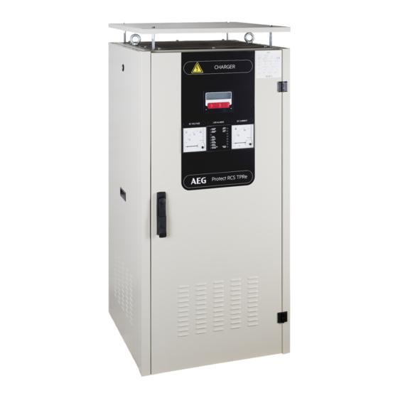
- Page 1 PROTECT RCS Battery charger TPRe TD Operation manual BN 092671/01/01 – 07/04/2020...
- Page 2 AEG Power Solutions is a world specialist in AC and DC power conversion. The company designs and manufactures rectifiers, inverters and power electronics systems associated with all types of batteries. The applications range from Transmission and distribution, Oil & Gas, Petrochemicals, Transport, Power, Manufacturing and Telecommunications Industries through to Military applications.
-
Page 3: Table Of Contents
CONTENTS INTRODUCTION ................4 PRESENTATION OF THE SYSTEM ..........5 INSTALLATION ................7 3.1 HANDLING ....................7 3.2 INSTALLING AND SECURING THE RECTIFIER CHARGER ....9 3.3 INSTALLING THE BATTERY ..............10 3.4 ENVIRONMENTAL REQUIREMENTS (EXCLUDING THE BATTERY) 10 CONNECTIONS (refer to the PRODUCT drawing) ...... 11 4.1 MAINS INPUT CONNECTION ............... -
Page 4: Introduction
To use the system properly, the user should first read this manual carefully. AEG is not be responsible for damage due to improper use, neglect, alterations, or use of other than original parts without our written consent. -
Page 5: Presentation Of The System
Front door options Charger mounting Front door Transformer behind plate and options options the mounting plate The PROTECT RCS TPRe TD range offers the following standard ratings and cabinet cooling features : PROTECT RCS TPRe TD BATTERY 125/127 VOLTAGE (VDC) 20A (N) - Page 6 Charger internal layout description : Charger options (marked with (*) Charger standard components : Analog rectifier output ammeter (P1) Input/output terminal block (X1-X2) Analog rectifier output voltmeter (P2-F21) Mains input EMC filter (Z1) depending on Front panel alarm LEDs (A6) charger rating ...
-
Page 7: Installation
3 INSTALLATION The system is delivered as shown hereafter. Natural cooling cabinet Forced cooling cabinet The equipment is fixed onto a pallet. 3.1 HANDLING The equipment must be handled with care, always in a vertical position. Labels on the outside of the package show the top and bottom. - Page 8 The TPRe TD rectifiers are delivered on pallets for easy handling using a pallet truck. For the transport of cabinets, always watch for the center of gravity. Check that the eye bolts are screwed fully home. The length of the slings calculated so that a minimum angle is given between the cable and the top edge of the cabinet.
-
Page 9: Installing And Securing The Rectifier Charger
3.2 INSTALLING AND SECURING THE RECTIFIER CHARGER Select an installation site with the following characteristics: Ambient temperature and relative humidity as specified in section 3.4. Ambient air free from dust and corrosive gases. Floor sufficiently flat. Floor sufficiently strong to carry the weight of the equipment. Sufficient space at the front to open the door (see picture below). -
Page 10: Installing The Battery
3.3 INSTALLING THE BATTERY The ground or floor must be strong enough to carry the weight of the batteries and/or stands or cabinets in which they are mounted. 3.4 ENVIRONMENTAL REQUIREMENTS (EXCLUDING THE BATTERY) Storage in standard carboard packing box Temperature: - 25°C to +70°C Relative humidity:... -
Page 11: Connections (Refer To The Product Drawing)
The external battery shunt must be inserted on the negative polatity of the battery, never on the positive polarity as this will damage the charger control board. Please contact AEG Power Solutions Customer Service Department. 4.1 MAINS INPUT CONNECTION DANGER, IF THE RECTIFIER IS EQUIPPED WITH AN OPTIONAL INPUT FILTER: MAINS INPUT: HIGH LEAKAGE CURRENT. -
Page 12: Battery Connection
4.2 BATTERY CONNECTION IMPORTANT RECOMMENDATIONS REFER TO THE BATTERY MANUAL. Refer to the battery manufacturer's instructions for the storage conditions. Never short-circuit a battery. IN ANY CASE, a battery short-circuit and overcurrent protection must be connected between the battery and the charger if the charger is not equipped with such a protective device. -
Page 13: Connecting The Load
4.4 CONNECTING THE LOAD Connect the load (+) to the load (+) terminal of the equipment. Connect the load (-) to the load (-) terminal of the equipment. 5 START-UP (REFER TO THE PRODUCT DRAWING) 5.1 PRELIMINARY CHECKS All circuit-opening devices must be in the "open" position. Check that the mains line protective device rating has the appropriate rating (see section 4.1). -
Page 14: Switching On
After a few seconds, the display shows: Vxx.yy and aa.bb are the software versions of the AEG PS-GCAU two micro controllers of the GCAU board Vxx.yy/aa.bb After a few seconds, the display shows the floating voltage and the rectifier current (at no-load). -
Page 15: Start-Up Procedure Of Tpre Td Paralleled Systems
Dangerous voltages exist across the battery and/or load terminals. Take the necessary safety precautions. We recommend to change “user” and “supervisor” passwords to prevent bad handlings. Refer to paragraph 6.7.3. 5.3 START-UP PROCEDURE OF TPRE TD PARALLELED SYSTEMS In the case of TPRe TD units with battery (each one) connected in parallel for redundancy, respect the following instructions : Check that the output protective device of each unit is open. -
Page 16: Operating Instructions
6 OPERATING INSTRUCTIONS The following section explains the basic operator menu structure of your system. It allows you to access all necessary functions in order to operate your system. The menus, indications and controls available depend on the system configuration. The keyboard assembly has two LEDs indicators: green LED: "System OK"... - Page 17 5 minutes inactivity - Menu overview - Default menu see § 6.1 Left key menu Measurements Output voltage, battery current, load voltage, AC voltage, battery temperature, ambient Monitoring temperature, battery charge, charger timer, date and time see § 6.5.1 see § 6.5 Alarm list Alarm text, “RESET”...
-
Page 18: Human Interface Structure
6.3 HUMAN INTERFACE STRUCTURE The human interface is based on consistency in operation. Consistency means that the functions are grouped logically within the menu structure and will provide ease of use for the operator. The LCD Display has 2 lines by 16 characters. The top line is always used to indicate information while the bottom line is used for the menu structure indication. -
Page 19: Monitoring Function
6.5 MONITORING FUNCTION 6.5.1 How to Display the Measurements You will find the measurements menus under the Monitoring function. The Monitoring function will display all relative meter indications on the top line of the LCD. Follow the instructions below. From the main menu select ‘Monit’. FLOATING CHARGE Monit Confg Cmnd... - Page 20 6.5.2 How to Display the Alarm List You will find the Alarm list indication under the Monitoring function. This Alarm List indication will display all active alarms on the top line of the LCD. Follow the instructions below. From the main menu select ‘Monit’. FLOATING CHARGE Monit Confg Cmnd...
- Page 21 6.5.3 How to Read the Alarm and Event Memory List (History List) The control board GCAU in your system is equipped with an Alarm and Event list. The GCAU board stores the alarm and events, in order of appearance, in a non-volatile memory (permanent storage). Events in this context means indicating if the system has been switched to High rate, Float or Commissioning, Entering the setup mode, Clearing the history etc.
-
Page 22: Command Function
6.6 COMMAND FUNCTION According to the factory set configuration, your system can have several specific command functions. All these commands are accessible through the Command function ‘Cmnd’. The different command functions are: Manual High rate Charge Manual Commissioning Charge Manual floating Charge Manual Adjustment of Voltage and/or Current Battery Test Function Clear History List... - Page 23 6.6.2 How to Activate Manual Commissioning Charge The Manual Commissioning charge is a command function and is located under the Command (‘Cmnd’) key. To prevent accidental activation, this command can be password protected if required. Follow the instructions below. Starting from the main menu, select ‘Cmnd’. FLOATING CHARGE Monit Confg Cmnd...
- Page 24 6.6.3 How to activate Manual Floating Charge When you are in high rate or commissioning charge mode, you can manually switch the rectifier in the floating charge mode. Follow the instructions below. HIGHRATE CHARGE COMMISSIONING Monit Confg Cmnd Monit Confg Cmnd Starting from the main menu, select ‘Cmnd’.
- Page 25 How to Adjust the Voltage and Current (Manual Adjustment) The procedure below explains how to adjust the voltage and current if the manual Voltage and/or Current option is activated. FLOATING CHARGE POWER SUPPLY Monit Confg Cmnd Monit Confg Cmnd Current adjustment only activated Voltage adjustment activated (current adjustment activated or no).
- Page 26 6.6.5 Battery capacity test Function (OPTION) The Battery Test feature can be used to test the battery performance. The test can be initiated manually or automatically. Three programmable parameters define the battery test: Discharge Current End Voltage Tolerance percentage. Warning: Contact the nearest agent of your equipment for details of the above settings.
- Page 27 6.6.6 How to Clear the Event and Alarm History List If required, the event and alarm history list of your system can be cleared from the front panel. A password on Supervisor or User level is mandatory to clear the list. Follow the instructions below.
- Page 28 6.6.7 How to reset Ah Meter (OPTION) FLOATING CHARGE Monit Confg Cmnd Starting from the main menu, select ‘Cmnd’. Select ‘Next’ until the following menu is displayed. AH METER WRONG PASSWORD Next Enter Exit Press ‘Enter’. Password: 1111 Enter A Supervisor or User level password is required to continue.
-
Page 29: Configuration Functions
6.7 CONFIGURATION FUNCTIONS 6.7.1 How to Change the Language Two languages are available in your GCAU board: the standard language (English) and a second one: the one you specified when you ordered your equipment. To change the language, follow the instructions below: Starting from the main menu select ‘Confg’. - Page 30 6.7.3 Setup The setup menu is accessible with a “user” or “supervisor” password and it allows the modification of your system configuration. The default “user” password is 1111. For supervisor access password please contact factory. Any modification of your system configuration is your responsibility. You risk damages on your battery or equipment if the modification is done by a non specialized staff.
- Page 31 We can distinguish 2 scenarios: NOT THE SAME PASSWORD CHANGED In the second case, you must start again. USER LEVEL Next Change Exit For the user level, apply the same procedure. 6.7.3.2 System setup With the “supervisor” password, you have access to the following setup: Battery selection: to select battery type, number of cells etc…...
- Page 32 6.7.3.3 Alarms and events setup The alarms setup menus are available with the “user” password and enable to set up the thresholds and the time- delay of the accessible alarms. The "supervisor" password enables to set up all parameters of the accessible alarms and events. Alarms list: High mains voltage alarm parameters.
- Page 33 Select ‘Next’ until the required alarm name is displayed, HIGH MAINS VOLT then select ‘Enter’. Example on ‘Charger current limit’ Next Enter Exit CHARGER CURR.LIM Next Enter Exit Select ‘Next’ until the ‘Function’ section is reached FUNCTION : Use the arrow keys to select ‘ALARM’ ...
-
Page 34: Functional Description
7 FUNCTIONAL DESCRIPTION The Protect RCS TPRe TD rectifiers are thyristor-controlled rectifiers suitable for charging nickel-cadmium or lead- acid batteries while supplying DC loads. The rectifier can be also used without batteries as direct power supplies. 7.1 OPERATING SEQUENCES Rectifier with associated battery Mains power ON –... -
Page 35: Charge Modes
7.2 CHARGE MODES The following battery charge modes are available (depending on the equipment): Floating charge Floating charge compensates for the self-discharge of the battery and, in normal operation, maintains the battery in a fully charged condition. High rate charge (or equalizing charge) High rate charge restores the battery to full capacity. -
Page 36: Gcau" Generic Control And Alarm Unit (A1)
The mains voltage is applied to the primary winding of the power transformer via the standard mains input breaker. The rectifier is then in service, provided no fault has been detected and/or stored by the monitoring systems. The power converter consisting of a full thyristor bridge rectifies the transformer secondary voltage. The rectifier current is smoothed by an inductor integrated inside the transformer and the voltage is filtered by capacitors. -
Page 37: Display Board (A300) And Keyboard Assembly (A310)
7.6 DISPLAY BOARD (A300) AND KEYBOARD ASSEMBLY (A310) The display board is mounted on the front of the system and is controlled by the GCAU board, via the interface board A4. It is a plug-in device and is connected through two RJ 4-4 connectors with a 4-wire cable. All data and necessary power supply voltages are transferred over this cable. - Page 38 8.1.2 Relay boards (A5) – Plug-in type Relay boards A5 provide remote signalling of individual alarms on 8 dry contacts relays. The connection is achieved on screw type terminals. The board cable is connected as per folio “I2C communication buses” in product drawing. The default alarms available on alarm card are the following : Alarm contact electrical details : How to instal and activate this option on the control card : Refer to the option installation manual...
-
Page 39: Communication Options
An alarm is delivered on detection of a leakage current 10 mA between ground and one of the output polarities. How to activate this option on the control card : charger display, refer to § 6.7.3.3 “alarms and events” 8.2 COMMUNICATION OPTIONS Depending on configuration the Protect RCS rectifier charger can be equipped with the following communication options. 8.2.1 RS485 –... -
Page 40: Load Options
8.2.3 TCP/IP Communication – Plug-in type This option includes a NCS board connected to A71 (RS232 board) and allowing TCP/IP communication with the GCAU control board. The Modbus RTU interface connection option needs to be installed in the charger so that the TCP/IP communication can be implemented. - Page 41 8.4.3 Battery temperature compensation – Plug-in type The chargers can sense the battery ambient temperature. The sensor is located in a metal lug and can be mounted to the wall, on the battery rack or inside the battery cabinet by a screw. The connection from sensor to board is a 4 wire telephone cable.
- Page 42 Enter the Password setting as follows: Starting from the main menu, select ‘Confg’. FLOATING CHARGE Select ‘Next’ until the following menu is displayed. Monit Confg Cmnd Select ‘Enter’. SETUP Next Enter Exit With arrow keys, select the “supervisor” password and hit Password: 1111 ‘Enter’...
-
Page 43: Cabinet Options
batt reference duration test duration : new reference duration time test starts test stops The first time the battery test is performed the reference time is 0. This ensures that the first battery test logs a time greater than the reference time. Note: If required, you can manually set the reference time to 0. -
Page 44: Parallel Operation
9 PARALLEL OPERATION The Protect RCS rectifier charger can operate also as parallel system. The following configuration are available: System: Redundant - for a charger and/or battery redundancy. Parallel - to increase the power or to increase the battery capacity. -
Page 45: Maintenance
10 years. Its replacement must be done by specialized personnel. IMPORTANT This component, mounted on a support, must be recycled in compliance with the European Directive n° 91/157/EEC of 18.03.91. You can also apply to AEG Power Solutions by shipping back the used board (prepaid shipment). 10.1.2 Battery maintenance For the recommended battery maintenance procedures, refer to the battery manufacturer’s manual. -
Page 46: Fan Maintenance
10.2 FAN MAINTENANCE Rectifier bridge and cabinet fans: It is recommended to replace the fans every five years. This operation must be done by specialized personnel. 10.3 CAPACITORS MAINTENANCE It is recommended to replace the DC capacitors, the AC filter Z1 and the DC EMC filter Z2 every seven years. This operation must be done by specialized personnel. - Page 47 ALARM or EVENT PROBABLE CAUSE CORRECTIVE ACTION “CHARGER FAULT” . Low floating voltage with the rectifier not . Check the F1 fuse in current-limiting mode. Call the Customer Service Department. . Fuse F1 blown. . Check the mains voltage and the proper operation of the fans.
- Page 48 ALARM or EVENT PROBABLE CAUSE CORRECTIVE ACTION “TEMP SENSE ERROR” . Short or open circuit temperature sensor. . Check the sensor connection. . GCAU board fault (ADC) . Call the Customer Service Department. “HIGH BATT. TEMP.” High battery temperature. . Check the battery cabinet temperature.
- Page 49 ALARM or EVENT PROBABLE CAUSE CORRECTIVE ACTION “INTERNAL CHECK” Communication error between the Call the customer service microcontrollers or internal system error department. (e.g.: DC overvoltage protection, synchro pulse missed, TPC board error … etc.) “LONG CHARGE TIME” High rate charge time too long. Call the customer service department.
- Page 50 AEG PS – Technical data in this document does not contain any binding guarantees or warranties. Content only serves for information purposes and can be modified at any time. We will make binding commitments only upon receipt of concrete enquiries and customer notification of the relevant conditions. Due to the non-binding nature of these terms, we assume liability neither for the accuracy nor...