Table of Contents
Advertisement
TABLE OF CONTENTS
1 Safety Precautions----------------------------------------------- 2
2 Specifications ----------------------------------------------------- 3
3 General/Introduction -------------------------------------------- 4
4 Control panel ------------------------------------------------------ 5
5 Feature and Technical Description ------------------------- 6
6 Installation Instructions ---------------------------------------- 9
7 Operating Instructions-----------------------------------------13
8 Disassembly Instructions and Adjustments -----------25
9 Wiring Diagram (OUTLINE) Drawing ----------------------46
10 Troubleshooting Guide ----------------------------------------48
11 External Diameter -----------------------------------------------56
12 Exploded View and Replacement Parts List -----------58
Model No.
Product Color :White
Destination :Malaysia, Singapore, Thailand, Philippines
PAGE
© Panasonic Corporation 2016 Unauthorized copy-
ing and distribution is a violation of law.
Order No.APJWM160401CE
Washer Dryer
NA-D106X1
PAGE
Advertisement
Table of Contents

Related Manuals for Panasonic NA-D106X1


Summary of Contents for Panasonic NA-D106X1
- Page 1 8 Disassembly Instructions and Adjustments -----------25 9 Wiring Diagram (OUTLINE) Drawing ----------------------46 10 Troubleshooting Guide ----------------------------------------48 11 External Diameter -----------------------------------------------56 12 Exploded View and Replacement Parts List -----------58 © Panasonic Corporation 2016 Unauthorized copy- ing and distribution is a violation of law.
- Page 2 NA-D106X1 1 Safety Precautions...
- Page 3 NA-D106X1 2 Specifications Item / Model NA-D106X1WMY NA-D106X1WSG NA-D106X1WTH NA-D106X1WPH Rated Voltage and Frequency AC 220V - 240V AC 220V - 240V AC 220V AC230V Rated Frequency 50Hz 50Hz 50Hz 60Hz Destination Malaysia Singapore Thailand Philippines Product weight 74 kg (81 kg )
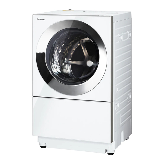
- Page 4 NA-D106X1 3 General/Introduction 3.1. Location of Components and Accessories...
- Page 5 NA-D106X1 4 Control panel...
- Page 6 NA-D106X1 5 Feature and Technical Description 5.1. Key feature 5.2. Foam maximize detergent power...
- Page 7 NA-D106X1 5.3. Active Foam system 5.4. ECONAVI...
- Page 8 NA-D106X1 5.5. Eco Drying system...
- Page 9 NA-D106X1 6 Installation Instructions...
- Page 10 NA-D106X1...
- Page 11 NA-D106X1...
- Page 12 NA-D106X1...
- Page 13 NA-D106X1 7 Operating Instructions 7.1. Door Lock and Child Lock...
- Page 14 NA-D106X1 7.2. Laundry Procedure...
- Page 15 NA-D106X1 7.3. Selecting the Program...
- Page 16 NA-D106X1 7.4. How to Put in Detergent and Sofetner...
- Page 17 NA-D106X1 7.5. Everyday Washing...
- Page 18 NA-D106X1 7.6. Washing Options...
- Page 19 NA-D106X1...
- Page 20 NA-D106X1 7.7. Drying...
- Page 21 NA-D106X1 7.8. Maintenance...
- Page 22 NA-D106X1...
- Page 23 NA-D106X1 7.9. Changing the Settings...
- Page 24 NA-D106X1 7.10. Program Details...
- Page 25 NA-D106X1 8 Disassembly Instructions and Adjustments Warning Connection of cables should be done according to regular work. • When drawing cables around, fixing those cables with cable suppression part. Do not touch rotating part, high temperature part and surface of metal.
- Page 26 NA-D106X1 2. Remove the Top mark C. 2. Remove 2 bottom Cap A screws, 2 bottom Top mark C (Remove the hooks (both sides). Push down the Top screws, 4 bottom Dry filter screws and 6 rear Top board mark C rearward to remove. In the direction of an arrow) screws, and then remove the Top board.
- Page 27 NA-D106X1 8.2.2. Replacement of Lead wire cover 2. Remove the 3 mounting screws from the controller (Display side). 1. Open the Door, remove the 1 Lead wire cover mounting screw and remove the Lead wire cover. 3. While pulling the lever of the Controller (Display side) upward, slide it to the side to remove.
- Page 28 NA-D106X1 8.2.4. Replacement of Door 8.3. Back panel, V belt, Pulley, 1. After performing the procedures for Replacement of Lid Motor sash (8.2.1), Replacement of Lead wire cover (8.2.2) and Replacement of Controller (Display side) (8.2.3), lift up 8.3.1. Replacement of Back panel the Door from the Lid hinge (top and bottom) and remove 1.
- Page 29 NA-D106X1 8.3.3. Replacement of the Impeller pulley 8.3.4. Replacement of Motor 1. Place the HW-6002 (Pulley breaking wrench) on the Impeller pulley, place the HW-25K (Flange nut remover Caution: tool) with HW-6001 (Hexagon nut adapter) set to it on the •...
- Page 30 NA-D106X1 2. Change the holding position of the motor to the direction 2. Unscrew the 2 Insulation spacer fixing screws, then shown in the figure and remove 2 Clamping bands fixing remove insulation spacer from the Controller (Power the lead wire, and then take out the motor.
- Page 31 NA-D106X1 8.5. Damper Important Notice 8.5.1. Replacement of Damper *When replacing the Controller (Power side), make sure to perform the mode d1 of the Service check D. 1. After performing the procedures for Replacement of Sensor calibration is performed. (TH1, TH2) Panel A (8.1.1), Replacement of Back panel (8.3.1) and...
- Page 32 NA-D106X1 8.6. Fan case U and Drying heater 3. After performing the procedure for Replacement of Back panel (8.3.1), stretch the Sub hose clamp securing the 8.6.1. Replacement of Fan case U Discharge air hose to disconnect the Discharge air hose from the Tank (outer tub).
- Page 33 NA-D106X1 4. Remove the 1 fixing screw securing the Fan case U with 7. Separation of the Fan case U from the Heater cover U the Body joint plate A to disconnect the Body joint plate A. • Remove the 6 Clamping bands and the 3 Fan case U fixing screws.
- Page 34 NA-D106X1 8.6.2. Replacement of Drying heater 8.7. 3D sensor, Water level sensor, 1. Remove the 6 Heater cover B fixing screws and the 2 Nozzle and Detergent case A Clamping bands, then remove Heater cover B. 8.7.1. Replacement of Water level sensor 1.
- Page 35 NA-D106X1 8.7.2. Replacement of 3D sensor 2. Remove the 1 Nozzle fixing screw and 5 Clamping bands fixing the lead wire, and then remove the Lead wire of the 1. After replacement Panel A, Dry filter, Filter frame and Top Water level sensor from 3 hooks.
- Page 36 NA-D106X1 8.8. Body B, Door lock switch, 5. Disengage the 8 hooks on the Detergent case A and Nozzle. Body band B, Body support D, Lid hinge cover and Lid hinge 8.8.1. Replacement of Body B 1. After performing the procedures for Replacement of Panel A, Dry filter, Filter frame and Top board (8.1),...
- Page 37 NA-D106X1 8.8.3. Replacement of Body band B 1. Use the longnose pliers to remove the Body band B. Refer to the figure below (the same disassembly procedure on both the front and rear sides). 8.8.4. Body band B (front side, back side) 8.8.5.
- Page 38 NA-D106X1 8.9. Wringer frame packing A, 8.10. Replacement of Drum unit Outer tub cover 1. After performing the procedures for Replacement of Back panel, V belt, Pulley, Motor, etc., (8.3) and Replacement 8.9.1. Replacement of Wringer frame of Wringer frame packing A, Outer tub cover (8.9), pull out the Drum unit from the front side of body.
- Page 39 NA-D106X1 8.11. Hal sensor U, Circulation 8.11.3. Replacement of Drain pump and Separetor After taking out pump, Drain pump and Separator Assembly (Separator + Separator. Drain pump) from Base, remove 8.11.1. Replacement of SF switch U (Hall Drain pump from Separator.
- Page 40 NA-D106X1 8.12. Replacement of Heater (water 3. Tilt the body down to the left. The body surface will touch the floor, so be sure to use the Protective sheet before heater) tilting it down. *Include replacement of Sensor 4. Remove 2 Clamping bands and 2 screws.
- Page 41 NA-D106X1 6. Removing the 1 connector and 1 Clamping band enables 7. Take the Heater off. you to disassemble as shown in the figure below. *At this point, the Sensor U and Heater switch plate can be removed. *At this point, the Connector lead wire DU can be...
- Page 42 NA-D106X1 8.13. Replacement of Feeding valve 4. Remove the 2 Feeding valve fixing screws. 1. After performing the procedures for Replacement of Panel A, Dry filter, Filter frame and Top board (8.1), Replacement of Back panel (8.3.1), remove 4 Body support A mounting screws.
- Page 43 NA-D106X1 8.14. Warm air sensor (TH3), Sensor 2. Remove the 6 Heater cover B fixing screws. U (TH1,TH2), Discharge air hose and Exhaust air hose 8.14.1. Replacement of Warm air sensor (TH3) 1. Upon completion of procedures 1 through 6 of the Fan case U (8.6.1), pull out the Sensor built-in cord seal...
- Page 44 NA-D106X1 8.14.3. Replacement of Discharge air hose *Points to note when assembling the Sensor U (TH1, TH2) and Exhaust air hose Insert the Sensor U (TH1, TH2) into the hole in the narrow 1. When the Heater cover block is pulled out in the pitch area as shown in the figure below.
- Page 45 NA-D106X1 8.15. Replacement of Noise filter 1. After performing the procedures for Replacement of Back panel (8.3.1), remove 2 Body joint plate B fixing screws. 2. Remove the 2 fixing screws securing the Chemical capacitor cover and Earth. 3. Remove all Connectors.
- Page 46 NA-D106X1 9 Wiring Diagram (OUTLINE) Drawing 9.1. NA-D106X1 Wiring Diagram...
- Page 47 NA-D106X1 9.2. Measure Input and Output value of Controller (Power side)
- Page 48 NA-D106X1 10 Troubleshooting Guide 10.1. Service check 1. Press and hold Power switch button. 2. Press and hold both the "Wash" and "Rinse" buttons with one hand. i.e. Press and hold those three buttons simultaneously. 3. Release your fingers from the buttons.
- Page 49 NA-D106X1 Number of Check Checking contents LED display indication Operation contents times "Wash" process button is pressed • Water supply Panel display : "Wash""Rinse" and "Dry" blinks, LED check display indicate "8" and count down by one minute unit. • Wash with warm •...
- Page 50 NA-D106X1 Number of Check Checking contents LED display indication Operation contents times "Wash" process button is pressed • Displays the • Hold down "Program" button during Error message operation content displayed, contents of setting when occurred shall when the error has be indicated (Program, Wash &...
- Page 51 NA-D106X1 Number of Check Checking contents LED display indication Operation contents times "Wash" process button is pressed • Each time "Rinse" • Each time "Rinse" button is pressed, displays those button is pressed, operation times in the following order. displays those •...
- Page 52 NA-D106X1 10.2. SELF DIAGNOSIS FUNCTION (ERROR DISPLAY) • The error is detected during operation, the error is displayed and the operation is stopped. • Displays the alphabet (U or H) and error number alternately. • The warning buzzer beeps for all "U" and "H21".
- Page 53 NA-D106X1 Display Contents Detection contents Check point Method to clear error *Unable to detect the water level 150mm or (Water is supplied) Press Start/Pause less in 5 minutes (after the initial drainage • Check the water leakage caused by button in door closed has started during the washing process).
- Page 54 NA-D106X1 Display Contents Detection contents Check point Method to clear error Malfunction of water Open circuit or short circuit is caused in the (Open circuit of water heater circuit.) Power button off and heater drive circuit. water heater circuit. • Check the relay connector has not come on again.
- Page 55 NA-D106X1 Display Contents Detection contents Check point Method to clear error Malfunction of Drying Open circuit or short circuit is caused in the (Open circuit of Drying heater circuit.) Power button off and heater operation Drying heater circuit. • Check the relay connector has not come on again.
- Page 56 NA-D106X1 11 External Diameter...
- Page 57 NA-D106X1...
- Page 58 NA-D106X1 12 Exploded View and Replacement Parts List 12.1. Parts Exploded View : Part A...
- Page 59 NA-D106X1 12.2. Replacement Parts List : Part A Safety Ref. Part No. Part Name & Description Q'ty Remarks AXW9907K9UU0 DRYING INSTRUCTION Malaysia,Singapore,Philippines AXW9907K9UW0 DRYING INSTRUCTION Thailand AXW3WK9UU0 FILTER B UNIT Malaysia,Singapore,Philippines,INCLUDES A01 AXW3WK9UW0 FILTER B UNIT Thailand,INCLUDES A01 AXW537W6SH0 CAP C...
- Page 60 NA-D106X1 12.3. Parts Exploded View : Part B...
- Page 61 NA-D106X1 12.4. Replacement Parts List : Part B Safety Ref. Part No. Part Name & Description Q'ty Remarks AXW1BK9FX0 BODY B AXW1111K9SG0 LID HINGE COVER AXW24SK9UU0 PANEL FACE A UNIT INCLUDES B04 AXW146K9UU0 PANEL FACE B AXW545K9SG0 LEAD WIRE COVER...
- Page 62 NA-D106X1 12.5. Parts Exploded View : Part C...
- Page 63 NA-D106X1 12.6. Replacement Parts List : Part C Safety Ref. Part No. Part Name & Description Q'ty Remarks AXW24N-9CV0 SENSOR UNIT 3D Sensor AXW1231-9SG0 BALANCE WEIGHT Upper center of OUTER TUB COVER AXW3224-9UU0 OUTER TUB COVER AXW2228-8RT0 BAFFLE AXW22B-9SG0 DRUM A UNIT...
- Page 64 NA-D106X1 12.7. Parts Exploded View : Part D...
- Page 65 NA-D106X1 12.8. Replacement Parts List : Part D Safety Ref. Part No. Part Name & Description Q'ty Remarks AXW8C-9CW0 PUMP UNIT Circulation pump AXW728-7EP0 SLEEVE COVERING AXW235-7EP0 SUCTION HOSE A AXW237-9SG0 DRAIN HOSE A Circulation pump to OUTER TUB COVER...
- Page 66 NA-D106X1 12.9. Parts Exploded View : Part E...
- Page 67 NA-D106X1 12.10. Replacement Parts List : Part E Safety Ref. Part No. Part Name & Description Q'ty Remarks AXW90E-7WX0 OUTER TUB SUPPORT UNIT Fixing brackets for transportation AXW156-9UU0 BACK PANEL AXW111-9SG0 BODY SUPPORT A Top rear AXW106-9UU0 BODY JOINT PLATE A...
- Page 68 NA-D106X1 12.11. Parts Exploded View : Packing 12.12. Replacement Parts List : Packing Safety Ref. Part No. Part Name & Description Q'ty Remarks AXWCZK9UU0 PROTECTION CASE A AXWTZ-9UU0 OPERATING INSTRUCTION Malaysia,Singapore,Philippines AXWTZ-9UW0 OPERATING INSTRUCTION Thailand AXWTZ-9UV1 OPERATING INSTRUCTION Malaysia AXW90B-9UU0...